
16.5 ADDER-SUBTRACTOR
An adder-subtractor based on Algorithm 16.4 will now be synthesized. It is made up of four parts, namely, alignment, addition, normalization, and rounding.
16.5.1 Alignment
The alignment circuit implements the three first lines of the algorithm, that is,
if operation=1 then sign2:=1 – sign2; end if;
if e1<e2 then swap(sign1, sign2); swap(s1, s2); swap (e1, e2);
end if;
e:=e1; s2:=s2/B**(e1-e2); sign:=sign1;
An example of the implementation is shown in Figure 16.1. The principal component is a shifter.
Given a (2.p + 4)-component vector
![]()
the shifter generates a (2.p + 4)-component output vector
![]()

Figure 16.1 Alignment circuit.
The sticky-digit circuit generates an output value 1 if at least one of its inputs is positive. If B = 2, the sticky-digit circuit is an OR circuit. Observe that if e1 − e2 is equal to p + 3, then the shifter output is equal to
[0 0..0 new_s2(0) new_s2(-1)..new_s2(-p)].
Taking into account that new_s2 is either s1 or s2, i.e. a normalized significand, new_s2(0) is positive. Thus the sticky digit is equal to 1 and the value of aligned_s2 is
[0 0..0 0 1].
If e1 − e2 were greater than p + 3, the value of aligned_s2 should be the same, so that it is not necessary to shift new_s2 more than p + 3 positions.
16.5.2 Additions
Depending on the respective signs of the aligned operands, one of the following operations must be executed:
- if they have the same sign, the sum aligned_s1 + aligned_s2 must be computed;
- if they have different signs, the difference aligned_s1 − aligned_s2 is computed, and if the difference is negative, the alternative difference aligned_s2 − aligned_s1 must be computed.
In the circuit of Figure 16.2 two additions are performed in parallel:

where the actual operation is selected with the signs of the operands, and
16.5.3 Normalization
The normalization circuit executes the following part of Algorithm 16.4:
if sign xor sign=0 then
  s:=s1+s2;
  if s>=B then e:=e+1; s:=s/B; end if;
else
  if (e1=e2) and (s1<s2) then swap(s1, s2); sign:=1-sign;
  end if;
  s:=s1-s2;
  leading_zeroes(s, k);
  s:=s*(B**k); e:=e-k;
end if;
If the number of leading zeroes is greater than p + 3, that is, s1 – s2 < B−(p + 2), then s2 > s1 – B−(p + 2). If e1 were greater than e2, then s2 ≤ (B – ulp)/ B = 1 − B−(p + 1) so that 1 − B−(p + 1) ≥ s2 > s1 − B−(p + 2) ≥ 1 − B−(p + 2), that is, B−(p + 1) < B−(p + 2): impossible! Thus the only case where the number of leading zeroes can be greater than p + 3 is when e1 = e2 and s1 = s2. If more than p + 3 leading 0′s are detected in the circuit of Figure 16.3, a zero_flag is raised.
As the arithmetic operations have already been performed (addition circuit, Figure 16.2), it remains to execute the following algorithm where operation is the internal operation computed in Figure 16.2:
if operation=0 then
  s:=result;
  if s>=B then e:=e+1; s:=s/B; end if;
else
  if (e1=e2) and (s1<s2) then s:=alt_result; sign:=1-sign;
else s:=result; end if;
  leading_zeroes(s, k);
  s:=s*(B**k); e:=e-k;
end if;
A possible implementation is shown in Figure 16.3.
16.5.4 Rounding
An example of the rounding circuit implementation is shown in Figure 16.4. If the round to the nearest, tie to even method is used (Algorithm 16.8), the block named rounding decision computes the following Boolean function decision:

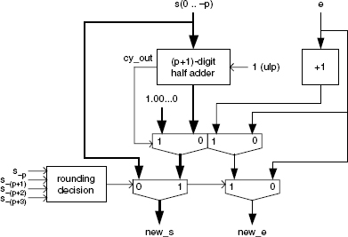
if s(-(p+1))<B/2 then decision:=0;
elsif s(-(p+1))>B/2 then decision:=1;
elsif (s(-(p+1))=B/2) and (s(-(p+2))>0) and (s(-(p+3))>0)
then decision:=1;
elsif (s(-(p+1))=B/2) and (s(-(p+2))=0) and (s(-(p+3))=0) and
((s(-p) mod 2)=0) then decision:=0;
elsif (s(-(p+1))=B/2) and (s(-(p+2))=0) and (s(-(p+3))=0) and
((s(-p) mod 2)=1) then decision:=1;
end if;
Example 16.7 (Complete VHDL code available.) Generate the VHDL model of a generic floating-point adder-subtractor. It is made up of four blocks:
1. Alignment (Figure 16.1):
entity alignment is
port (
  sign1, sign2, operation: in std_logic;
  e1, e2: in integer;
  s1, s2: in digit_vector(0 downto -p);
  dif: inout natural;
  sign, new_sign2: out std_logic;
  e: out natural;
  aligned_s1, aligned_s2: out digit_vector(0 downto -(p+3))
);
end alignment;

architecture behavior of alignment is
  signal actual_sign2: std_logic;
  signal s, new_s2: digit_vector(0 downto -p);
  signal shift_length: natural;
  signal sticky: digit;
begin
  actual_sign2<=operation xor sign2;
  swap: process(sign1, actual_sign2, e1, e2, s1, s2, s)
  begin
    if e1<e2 then
      dif<=e2-e1; e<=e2; sign<=actual_sign2;
      new_sign2<=sign1; s<=s2; new_s2<=s1;
    else
      dif<=e1 – e2; e<=e1; sign<=sign1;
      new_sign2<=actual_sign2; s<=s1; new_s2<=s2;
    end if;
    aligned_s1(-(p+1))<=0; aligned_s1(-(p+2))<=0;
    aligned_s1(-(p+3))<=0;
    for i in 0 downto -p loop aligned_s1(i)<=s(i); end loop;
    end process swap;
    barrel_shifter: process(dif, shift_length, new_s2, sticky)
      variable a: digit_vector(0 downto -(2*p+3));
      variable acc_or: digit;
    begin
      for i in -(p+1) downto -(2*p+3) loop a(i):=0; end loop;
      for i in 0 downto -p loop a(i):=new_s2(i); end loop;
      if dif<p+3 then shift_length<=dif;
      else shift_length<=p+3; end if;
      if shift_length>0 then
        for j in 1 to shift_length loop
          for i in -(2*p+3) to -1 loop a(i):=a(i+1); end loop;
          a(0):=0;
        end loop;
      end if;
      acc_or:=0;
      for i in -(p+3) downto -(2*p+2) loop
        if (a(i)>0) or (acc_or>0) then acc_or:=1; end if;
      end loop;
      sticky<=acc_or;
      aligned_s2<=a(0 downto -(p+2))&sticky;
    end process barrel_shifter;
  end behavior;
2. Addition (Figure 16.2):
entity addition is
port (
  sign, sign2: in std_logic;
  aligned_s1, aligned_s2: in digit_vector(0 downto -(p+3));
  int_operation: inout std_logic;
  result, alt_result: out digit_vector(1 downto -(p+3))
);
end addition;

architecture rtl of addition is
  signal long_s, long_s2: digit_vector(1 downto -(p+3));
  signal inv_s, inv_s2: digit_vector(1 downto -(p+3));
  signal carry1: mybit_vector(1 downto -(p+3));
  signal carry2: mybit_vector(1 downto -(p+3));
begin
  int_operation<=sign xor sign2;
  long_s<=0&aligned_s1; long_s2<=0&aligned_s2;
  inverters1: for i in -(p+3) to 1 generate
    inv_s2(i)<=B-1-long_s2(i) when int_operation=‘1’
    else long_s2(i);
  end generate;
  inverters2: for i in -(p+3) to 1 generate
  inv_s(i)<=B-1-long_s(i);
  end generate;
  carry1(-(p+3))<=int_operation;
  first_adder: for i in -(p+3) to 0 generate
     carry1(i+1)<=‘1’ when long_s(i)+inv_s2(i) +
     conv_integer(carry1(i))>B-1 else ‘0’;
     result(i)<=(long_s(i)+inv_s2(i) +
     conv_integer(carry1(i))) mod B;
  end generate;
  result(1)<=(long_s(1)+inv_s2(1)+conv_integer(carry1(1)))
  mod B;
  carry2(-(p+3))<=‘1’;
  second_adder: for i in -(p+3) to 0 generate
    carry2(i+1)<=‘1’ when inv_s(i)+long_s2(i) +
    conv_integer(carry2(i))>B-1 else ‘0’;
    alt_result(i)<=(inv_s(i)+long_s2(i) +
    conv_integer(carry2(i))) mod B;
  end generate;
  alt_result(1)<=(inv_s(1)+long_s2(1)+
  conv_integer(carry2(1))) mod B;
end rtl;
3. Normalization (Figure 16.3):
entity normalization is
port (
  sign, operation: in std_logic;
  e, dif: in natural;
  result, alt_result: in digit_vector(1 downto -(p+3));
  new_sign, zero_flag: out std_logic;
  new_s: out digit_vector(0 downto -(p+3));
  new_e: out natural
);
end normalization;

architecture behavior of normalization is
  signal result_div_B, s1, s, s2: digit_vector(0 downto -
  (p+3));
  signal exp1, k, exp2: natural;
  signal sign1, sign2: std_logic;
begin
  divide_by_B: for i in -(p+3) to 0 generate
    result_div_B(i)<=result(i+1);
  end generate;
  s1<=result(0 downto -(p+3)) when result(1)=0 else
  result_div_B;
  exp1<=e when result(1)=0 else e+1; sign1<=sign;
  s<=alt_result(0 downto -(p+3)) when (dif=0) and
  (result(1)>0) else result(0 downto -(p+3));
  leading_zeroes: process(s)
    variable var_k: natural;
  begin
    var_k:=0;
    for i in 0 downto -(p+3) loop
      if s(i)>0 then exit; end if;
      var_k:=var_k+1;
    end loop;
    if var_k=p+4 then zero_flag<=‘1’; else zero_flag<=‘0’;
    end if;
    k<=var_k;
  end process leading_zeroes;
  shift_k: process (s, k)
    variable a: digit_vector(0 downto -(p+3));
  begin
    a:=s;
    if k>0 then
      for i in 1 to k loop
        for i in 0 downto -(p+2) loop a(i):=a(i-1); end loop;
      a(-(p+3)):=0;
      end loop;
    end if;
    s2<=a;
  end process shift_k;
  exp2<=e-k;
  sign2<=not(sign) when (dif=0) and (result(1)>0) else sign;
  new_s<=s1 when operation=‘0’ else s2;
  new_e<=exp1 when operation=‘0’ else exp2;
  new_sign<=sign1 when operation=‘0’ else sign2;
end behavior;
4. Rounding (Figure 16.4):
entity rounding is
port (
  s: in digit_vector(0 downto -(p+3));
  e: in natural;
  new_s: out digit_vector(0 downto -p);
  new_e: out natural
);
end rounding;

architecture behavior of rounding is
begin
    process(s)
      variable carry: digit_vector(1 downto -p);
      variable sum: digit_vector(0 downto -p);
  begin
    if s(-(p+1))<B_div_2 then new_s<=s(0 downto -p);
      new_e<=e;
    elsif (s(-(p+1))>B_div_2) or (s(-(p+2))>0) or
      (s(-(p+3))>0) or (s(-p) mod 2=1) then
      --plus ulp
      carry(-p):=1;
      for i in -p to 0 loop
        if s(i)+carry(i)>B-1 then carry(i+1):=1;
        else carry(i+1):=0; end if;
        sum(i):=(carry(i)+s(i)) mod B;
      end loop;
      ------
      if carry(1)=1 then
        new_s(0)<=1;
        for i in -1 downto -p loop new_s(i)<=0; end loop;
        new_e<=e+1;
      else new_s<=sum; new_e<=e; end if;
    else new_s<=s(0 downto -p); new_e<=e;
    end if;
  end process;
end behavior;
It remains to assemble the four blocks (Figure 16.5):
entity adder_subtractor is
port (
  sign1, sign2, operation: in std_logic;
  e1, e2: in integer;
  s1, s2: in digit_vector(0 downto -p);
  sign, zero_flag: out std_logic;
  e: out natural;
  s: out digit_vector(0 downto -p)
);
end adder_subtractor;

architecture circuit of adder_subtractor is
  component alignment…end component;
  component addition…end component;
  component normalization…end component;
  component rounding…end component;
  signal sign_a, sign2_a, int_operation: std_logic;
  signal e_a, dif, e_n: natural;
  signal aligned_s1, aligned_s2, s_n:
    digit_vector(0 downto -(p+3));
  signal result, alt_result:
    digit_vector(1 downto -(p+3));
begin
  alignment_component: alignment port map (sign1, sign2,
    operation, e1, e2, s1, s2, dif, sign_a, sign2_a, e_a,
    aligned_s1, aligned_s2);
  addition_component: addition port map (sign_a, sign2_a,
    aligned_s1, aligned_s2, int_operation, result, alt_result);
  normalization_component: normalization port map (sign_a,
    int_operation, e_a, dif, result, alt_result,
    sign, zero_flag, s_n, e_n);
  rounding_component: rounding port map (s_n, e_n, s, e);
end circuit;
