
11.2 INTEGERS
11.2.1 B's Complement Adders and Subtractors
The B's complement adder of Figure 11.46a is deduced from Algorithm 4.18. It consists of an (n + 1)-digit adder and two instances of the combinational circuit ext (digit extension) whose function is to represent x and y with an additional digit (sign digit):
![]()
Another circuit is shown in Figure 11.46b. Instead of generating an (n + 1)-digit output, this second adder generates an n-digit output and an overflow flag (Equation 4.17) is raised if the result cannot be expressed with n digits.
TABLE 11.4 Experimental Results
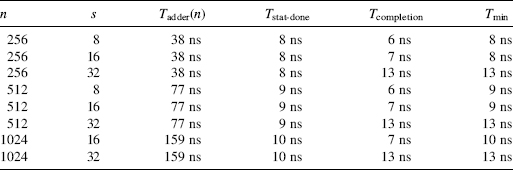

Figure 11.46 B's complement adders.
In order to synthesize a subtractor, or an adder-subtractor, another type of combinational circuit, namely, inv, is necessary. Given an n-digit number a, it computes
![]()
Two versions of a B's complement adder-subtractor are shown in Figure 11.47. The first one generates the exact (n + 1)-digit result. The other one generates an n-digit result and an overflow flag according to the relations (4.17) and (4.20). In both circuits the control signal defines the operation: addition (control = 0) or subtraction (control = 1).
Comments 11.9
- If the reduced B's representation is used—in particular, if B = 2—the digit extension just consists of repeating the most significant bit.
- If B = 2, the circuit inv is made up of n inverters. Furthermore the n inverters and the multiplexer could be replaced by n XOR gates (as in Figure 11.43b).
Example 11.16 (Complete VHDL code available.) Generate the VHDL model of a B's complement adder-subtractor (Figure 11.47a):
 entity example11_16 is
 port (
   x, y: in digit_vector(n-1 downto 0);
   control, d_in: in std_logic;
   z: out digit_vector(n downto 0)
 );
 end example11_16;
 architecture circuit of example11_16 is
   signal minus_y, operand_2: digit_vector(n-1 downto 0);
   signal carries: std_logic_vector(n downto 0);
   signal x_n, operand_2_n: digit;
 begin
   invert: for i in 0 to n-1 generate minus_y(i)<=B-1-y(i);
   end generate;
   with control select operand_2<=y when ‘0’,
   minus_y when others;
   x_n<=0 when x(n-1)<B/2 else B-1;
   operand_2_n<=0 when operand_2(n-1)<B/2 else B-1;
   carries(0)<=control xor d_in;
   adder: for i in 0 to n-1 generate
     iterative_step:
     z(i)<=(x(i)+operand_2(i)+conv_integer(carries(i))) mod B;
     carries(i+1)<=“0” when x(i)+operand_2(i)+conv_integer
     (carries(i))<B else ‘1’;
   end generate;
   z(n)<=(x_n+operand_2_n+conv_integer(carries(n))) mod B;
 end circuit;
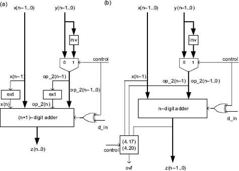
Figure 11.47 B's complement adder-subtractors.
11.2.2 Excess-E Adders and Subtractors
The circuit of Figure 11.48a, where E′ stands for the (n + 1)-digit representation of Bn+1 − 1 − E, is an excess-E adder based on Algorithm 4.22. The pos (positive) circuit detects whether z(n) is greater than 0, or not—if B = 2, the pos circuit is a simple connection. An excess-E subtractor, based on Algorithm 4.23, is shown in Figure 11.48b. As before, the inv circuit computes the (B − 1)'s complement y′ of y.

Figure 11.48 Excess-E adder and subtractor.
Example 11.17 (Complete VHDL code available.) Generate the VHDL model of an excess-E adder and subtractor.
 --excess-E adder
 entity example11_17 is
 port (
   x, y: in digit_vector(n-1 downto 0);
   c_in: in std_logic;
   z: out digit_vector(n-1 downto 0);
   ovf: out std_logic
 );
 end example11_17;
 architecture circuit of example11_17 is
   signal w: digit_vector(n downto 0);
   signal carries_1, carries_2: std_logic_vector(n downto 0);
   signal z_n: digit;
 begin
   --first adder:
   carries_1(0)<=c_in;
   adder_1: for i in 0 to n-1 generate
     iterative_step: w(i)<=(x(i)+y(i) +
     conv_integer(carries_1(i))) mod B;
     carries_1(i+1)<=‘0’ when x(i)+y(i)+conv_integer
     (carries_1(i))<B else ‘1’;
   end generate;
   last_step_1: w(n)<=conv_integer(carries_1(n));
   --second adder:
   carries_2(0)<=‘1’;
   adder_2: for i in 0 to n-1 generate
     iterative_step: z(i)<=(w(i)+minus_excess(i)
     +conv_integer(carries_2(i))) mod B;
     carries_2(i+1)<=‘0’ when w(i)+minus_excess(i)+
     conv_integer(carries_2(i))<B else ‘1’;
   end generate;
   last_step_2:z_n<=(w(n)+minus_excess(n)+conv_integer
   (carries_2(n))) mod B;
   ovf<=‘1’ when z_n>0 else ‘0’;
 end circuit;

 --excess-E subtractor
 entity example11_17bis is
 port (
   x, y: in digit_vector(n-1 downto 0);
   b_in: in std_logic;
   z: out digit_vector(n-1 downto 0);
   ovf: out std_logic
  );
  end example11_17bis;

  architecture circuit of example11_17bis is
    signal w: digit_vector(n downto 0);
    signal carries_1, carries_2: std_logic_vector(n downto 0);
    signal z_n: digit;
  begin
  --first adder:
  carries_1(0)<=‘0’;
  adder_1: for i in 0 to n-1 generate
    iterative_step: w(i)<=(x(i)+excess(i)+
    conv_integer(carries_1(i))) mod B;
    carries_1(i+1)<=‘0’ when x(i)+excess(i)+
    conv_integer(carries_1(i))<B else ‘1’;
  end generate;
  last_step_1: w(n)<=(excess(n)+conv_integer(carries_1(n)))
  mod B;
  --second adder:
  carries_2(0)<=not(b_in);
  adder_2: for i in 0 to n-1 generate
    iterative_step: z(i)<=(w(i)+
    (B-1-y(i))+
    conv_integer(carries_2(i))) mod B;
    carries_2(i+1)<=‘0’ when w(i)+(B-1-y(i))+
    conv_integer(carries_2(i))<B else ‘1’;
  end generate;
  last_step_2: z_n<=(w(n)+(B-1)+conv_integer(carries_2(n)))
  mod B;
  ovf<=‘1’ when z_n>0 else ‘0’;
end circuit;
11.2.3 Sign-Magnitude Adders and Subtractors
The circuit of Figure 11.49 implements Algorithm 4.26. The combinational circuit comp (comparator) detects whether a(n − 1) is greater than or equal to B/2; if B = 2 the comp circuit is a simple connection. As before, the inv circuit computes the (B − 1)'s complement of y or a. The control signal defines the operation: addition (control = 0) or subtraction (control = 1).

Figure 11.49 Sign-magnitude adder.
As the sign-change operation amounts to inverting the sign bit, the synthesis of a subtractor, or of an adder-subtractor, is straightforward: it's just a matter of substituting y(n − 1) by not (y(n − 1)), or by (y(n − 1) xor control).
Example 11.18 (Complete VHDL code available.) Generate the VHDL model of a sign-magnitude adder (Figure 11.49):
 entity example11_18 is
 port (
   x, y: in digit_vector(n-2 downto 0);
   sign_x, sign_y: in std_logic;
   z: out digit_vector(n-1 downto 0);
   sign_z: out std_logic
 );
 end example11_18;

 architecture circuit of example11_18 is
   signal minus_y: digit_vector(n-2 downto 0);
   signal operand_2, a, operand_2bis: digit_vector(n-1
   downto 0);
   signal minus_a: digit_vector(n-1 downto 0);
   signal carries_1, carries_2: std_logic_vector(n-1 downto 0);
 begin
   invert_y: for i in 0 to n-2 generate minus_y(i)<=B-1-y(i);
 end generate;
   carries_1(0)<=sign_x xor sign_y;
   with carries_1(0) select operand_2(n-2 downto 0)<=y when ‘0’,
   minus_y when others;
   with carries_1(0) select operand_2(n-1)<=0 when ‘0’,
   B-1 when others;
   adder_1: for i in 0 to n-2 generate
     iterative_step: a(i)<=(x(i)+operand_2(i)+
     conv_integer(carries_1(i))) mod B;
     carries_1(i+1)<=‘0’ when x(i)+operand_2(i)+
     conv_integer(carries_1(i))<B else ‘1’;
   end generate;
   a(n-1)<=(operand_2(n-1)+conv_integer(carries_1(n-1)))
   mod B;
   invert_a: for i in 0 to n-1 generate minus_a(i)<=B-1-a(i);
   end generate;
   carries_2(0)<=“0” when a(n-1)<B/2 else ‘1’;
   with carries_2(0) select operand_2bis<=a when ‘0’,
   minus_a when others;
   with carries_2(0) select sign_z<=sign_x when ‘0’,
   sign_y when others;
   adder_2: for i in 0 to n-2 generate
     iterative_step:
     z(i)<=(operand_2bis(i)+conv_integer(carries_2(i))) mod B;
     carries_2(i+1)<=“0” when operand_2bis(i)+
     conv_integer(carries_2(i))<B else ‘1’;
   end generate;
   z(n-1)<=(operand_2bis(n-1)+conv_integer(carries_2(n-1)))
   mod B;
 end circuit;