
Practical Example: Rigging Stickman
As you may have guessed, rigging is a pretty intensive process. You need to be technically minded and creative at the same time. The best riggers I've ever met are the sort of people who fit this description and have an eye for the big picture. These sorts of people enjoy playing Minesweeper, finding pleasure in solving the integrated relationships in each part of that game.
Well, regardless of whether you're one of these people, the best way to understand the full process of rigging is to actually create a rig of your own. The examples throughout the rest of this section are done with a simple stick figure character that I like to use for creating quick animations that test body language and timing. I love animating with stick figures, even in 3D. Ninety percent of an animated character's personality comes through in his body language. Animating with stick figures allows you to focus on that essential step and keeps you from getting distracted with secondary details.
This stick figure, in both rigged and unrigged versions, is included with the DVD that accompanies this book so that you have a finished reference, as well as a file, to practice with. Of course, if you have a character already modeled and want to rig it, that's great. You can use the techniques here for nearly anything you want to build a rig for.
Building Stickman's centerline
If you load the stickman.blend file from the DVD, the first thing you might notice is his pose. He's standing up with his arms out to his sides. This stance is referred to as a T pose because the character looks like the letter T. This pose is probably the most common one that modelers use when they create their characters, and it's the most preferred pose for riggers. Some modelers may also model with the arms at the sides, or sometimes they have the arms somewhere halfway between the T pose and having arms at the side. There are valid reasons people give for any of these poses, but ultimately it really comes down to personal preference.
Time to get an armature in this mesh. A good way to start is to create the centerline bones first: the body bones, the head, and the hipbone. To create these bones, use the following steps:
- Add your armature and start with the first body bone (Shift+A
 ArmatureSingle Bone).
 - Enable X-Ray viewing for the armature (Object Data PropertiesDisplayX-Ray).
This step ensures that you can always see the bones of your armature.
- Tab into Edit mode and move this bone up in the Z-axis until it's around Stickman's waistline (GZ).
- Select the tail of this bone and move it up in the Z-axis until it's at the top of the torso (right-click, GZ).
- Subdivide this bone into two bones (WSubdivide).
- Name the bottom bone body.1 and the top bone body.2.
- Select the joint between the two bones and move it back in the Y-axis a little bit (right-click, GY).
This step helps the bones match the natural curvature of the spine.
- Select the tail of body.2 and extrude it up in the Z-axis to the top of Stickman's head (right-click, EZ).
- Name this bone head.
- Select the head of body.1 and extrude it down in the Z-axis to the bottom of Stickman's pelvis (right-click, EZ).
- Name this bone hip.
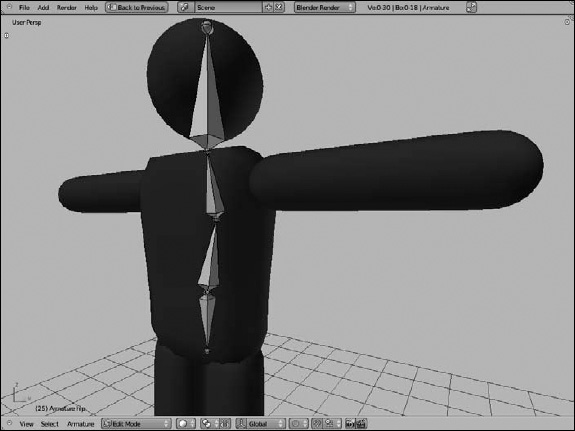
You have something that looks like Figure 11-14.
Adding Stickman's appendages
The next step is to create bones for the arms and the legs. You do so by creating bones for half of the rig and then letting Blender do the rest of the work for you by mirroring the bones. First things first, though — you have to create one-half of the rig:
- Switch to the front view, select the head bone, and duplicate it, putting its root at Stickman's left shoulder joint (Numpad 1, right-click, ShiftD).
Note that by working this way, the new bone is an offset child of the body.2 bone.
Figure 11-14: Stickman has an armature for his centerline.
- Name this new bone arm_upper.L.
- Select the tail of arm_upper.L and move it to Stickman's elbow.
It may help to press Ctrl to guarantee that the bone is perfectly horizontal (right-click, G
Ctrl). - Extrude this tail to create a new bone along the X-axis that extends to Stickman's hand (EX).
- Name this new bone arm_lower.L.
- From the front view, select the hipbone and duplicate it, placing the new bone's head at the top of Stickman's left leg (Numpad 1, right-click, Shift+D).
- Select this new bone's tail and move it along the Z-axis to Stickman's feet (right-click, GZ).
- Select this bone and subdivide it into two bones (right-click, WSubdivide).
- Name the top bone leg_upper.L and the bottom bone leg_lower.L.
- Select the joint between these bones and move it forward in the Y-axis a little bit (right-click, GY).
This step gives the knee a little bit of bend, which helps deformation when adding constraints.
- Parent leg_upper.L to hip (right-click leg_upper.L, Shift+right-click hip, Ctrl+PKeep Offset).
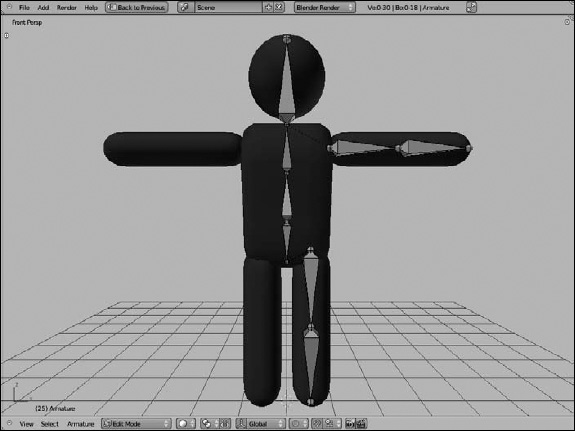
You now have something that looks like Figure 11-15.
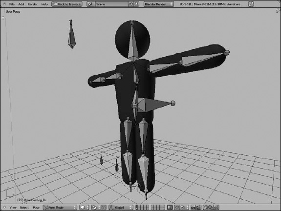
Figure 11-15: A half-skeleton Stickman!
Now for the really cool part of letting Blender do the work for you. You want to select all the bones that aren't on the centerline, duplicate them, and mirror them along the X-axis. Here are the specific hotkeys and steps:
- Select both arm bones and both leg bones using Border Select (B).
- Duplicate the selected bones and immediately press Esc (Shift+D, Esc).
The newly created bones appear in the exact same location as their originators.
- Have Blender automatically give these new bones the .R suffix to indicate that they're on the right side (WFlip Names).
All your bones are properly named now, but half of them are still in the wrong part of the rig. The next step is where the magic lies.
- Enable X-Axis Mirror in the Tool Shelf (Tool ShelfArmature OptionsX-Axis Mirror).
- Select all bones (AA).
- Grab your bones and immediately escape out of it (GEsc).
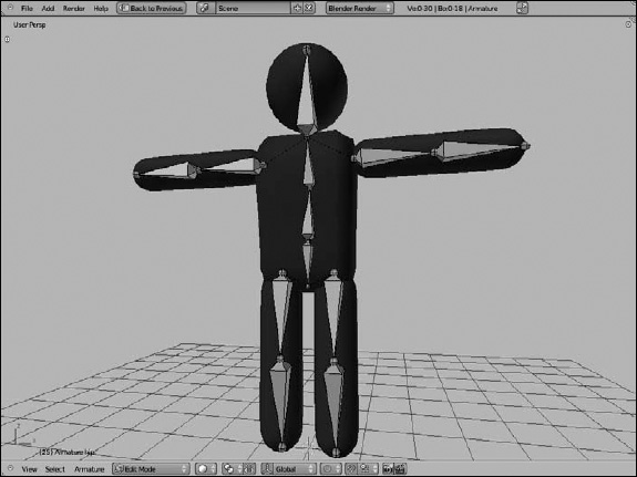
Pow! Instantly, your bones pop to their correct places and your rig now looks like what's in Figure 11-16.
Figure 11-16: Stickman with a skeleton in him. He's almost rigged, but he still needs some controls.
![]() As an astute reader, you may find yourself wondering why you didn't use Blender's Mirror operator (Ctrl+M) to flip Stickman's arms and legs to the correct side of his body. Unfortunately, sometimes the Mirror operation messes up the roll angle of bones in the rig. Letting the X-Axis Mirror feature handle things for you gives you a better chance of having correct roll angles on both sides of your character's rig.
As an astute reader, you may find yourself wondering why you didn't use Blender's Mirror operator (Ctrl+M) to flip Stickman's arms and legs to the correct side of his body. Unfortunately, sometimes the Mirror operation messes up the roll angle of bones in the rig. Letting the X-Axis Mirror feature handle things for you gives you a better chance of having correct roll angles on both sides of your character's rig.
Taking advantage of parenting and constraints
What you currently have in place is the basic structure of the rig's armature. The primary function of these bones is to deform the character mesh. Technically, you could animate with just these bones after you skin them to the mesh. However, you can (and should) add some additional bones to the armature to make it easier to animate. They work by taking advantage of the parenting set up by the bone chains and combining them with some reasonable constraints.
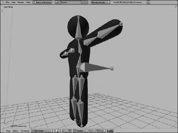
For example, you currently have a structured skeleton in place, but what happens if you Ctrl+Tab into Pose mode and grab the body.1 bone and move it (G)? Because the entire upper body is directly or indirectly a child of this bone, the upper torso, arms, and head move with the body.1 bone. Unfortunately, the lower half of the body doesn't share this relationship, so as Figure 11-17 shows, you end up tearing Stickman's skeleton in half. Ouch!
Figure 11-17: There's nothing relating the upper body to the lower body, so you can accidentally tear Stickman in half.

To compensate, you need a bone — called a root bone — that both the hip and body.1 bones relate to, binding the upper half of the body to the lower half. Moving this bone should move the entire armature. Adding a root bone to the rig is pretty simple:
- Tab into Edit mode on the armature and switch to the side view (Numpad 3).
- Select the head of either the body.1 or hip bones (right-click).
Both heads are located in the same place, so it doesn't really matter which one you select.
- Extrude a new bone along the Y-axis (EY) and name it root.
Move in the positive Y direction, toward the back of Stickman.
- Parent the body.1 and hip bones to the root bone (right-click body.1, Shift+right-click hip, Shift+right-click root, Ctrl+PKeep Offset).
This parent relationship means that you can move the entire armature by just selecting and moving the root bone. Before creating this parent relationship, some people may choose to switch the direction of the root bone (W
Switch Direction) so that they can have the root bone's tip actually connected to the heads of body.1 and hip. It's all a matter of taste, but I prefer not to. Because bones naturally rotate around their head, it's more useful to me to keep the head of the root bone in the center of the character. In my opinion, using this setup helps make bending at the waist look more natural. - Select the root bone and disable the Deform check box in its Bone Properties.
This bone is intended purely to control the other bones. You don't want any of the mesh's vertices assigned to it. Your Stickman rig now looks something like Figure 11-18.
Figure 11-18: Adding a root bone to the rig prevents the top of the body from unnecessarily leaving the bottom.
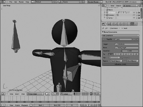
Another convenient control bone that you may want to add is a head control. Sure, you can rotate the head bone as you want, but using a bone as the head's (or eyes') target is often easier. That way, when you want the character to look at something, you just move the target bone to that something's location. An added benefit is that by building your rig this way, you can successfully create complex moves, such as keeping the character looking at an object as he walks by it. To add a head control to your rig, you use a Track To constraint:
- Tab into Edit mode and select the head bone (Tab, right-click).
- Duplicate the head bone and move it in the Y-axis (Shift+DY) and name it head_target.
The idea is that you want the control bone to be far enough in front of the face so that you can have some control without getting in the way of the rest of the rig. I moved mine about 3 units out.
- Clear the parent relationship on the head_target bone (Alt+PClear Parent).
Because the head_target bone came into being by duplicating the head bone, it inherited the parent relationship to the body.2 bone. You don't want this relationship because you want to be able to move the head target independently of the rest of the rig.
- Ctrl+Tab into Pose mode, select the head_target bone, and then also select the head bone (right-click, Shift+right-click).
- Add a Track To constraint to the head bone (Shift+Ctrl+CTrack To).
This step automatically adds a Track To constraint to the head bone's Bone Constraints Properties and makes the bone a nice shade of green. Chances are good that the head bone also rotates toward head_target and points directly at it — not the behavior you want. You need to change the alignment axes that the constraint works on.
- In the Track To constraint, change the To axis to -Z and the Up axis to Y.
This step fixes the head bone so that it points in the proper direction. Now when you grab (G) the head_target bone and move it around, the head bone always points at it.
- Select the head_target bone and disable the Deform check box in its Bone Properties.
Like the root bone, this bone isn't intended to deform the mesh, so disabling the Deform button ensures that it doesn't. Figure 11-19 shows what your rig looks like now.
Figure 11-19: The Stickman rig, now with head control!
Your Stickman is mostly functional now. However, another constraint is a staple of nearly all character rigs and is monumentally helpful to animators. It's called an inverse kinematics, or IK, constraint. The next section goes into what this constraint does, how it works, and how to give your rig its benefits.
Comparing inverse kinematics and forward kinematics
When it comes to animating characters in 3D with an armature, you have two ways to move limbs around: inverse kinematics and forward kinematics, or IK and FK. Kinematic is just a fancy way of saying motion. By default, your rig is set up to use FK. Say that you have a bone chain, and you want to place the tip of the last bone to a specific location in 3D space. In order to do so, you have to rotate the first bone in the chain, and then the next, and then the next, and so on until you can get that last bone's tip properly placed. You're working your way forward along the bone chain. Because of the parenting relationships between the bones, you can currently use FK with your Stickman rig.
That's FK. It gets the job done, but it can be awfully difficult and tedious to try to get the tip of that last bone exactly where you want it. It would be nice if you could just grab that tip, put it in place, and let the computer figure out how all the other bones have to bend to compensate. This method of letting the computer figure things out for you, basically, is the essence of IK. You move the tip of the last bone in the chain, and Blender works backward along the chain to get the other bones properly placed.
To see what IK is like, select your Stickman armature and Ctrl+Tab into Pose mode. Now, select the body.2 bone and press G to grab and move it. Notice that all the bone does is rotate; it doesn't actually change its location. Now go to Pose Options panel in the Tool Shelf and left-click the Auto IK check box. Auto IK isn't a real IK constraint, but it will help you understand how IK works. Grab (G) and move the body.2 bone. Notice that, now, this bone moves around, and the body.1 bone rotates to compensate for the locations that you try to put body.2. Selecting the head bone or one of the arm_lower bones results in similar behavior. Click around and play with Auto IK on your rig. It's pretty cool. When you're done, disable the Auto IK check box.
IK is really awesome stuff and it's very powerful, but it's not the ultimate solution for animating. See, one of the core principles of animation is that natural movement happens in arcs. Generally speaking, arcing movement is more believable and, well, natural looking. Things that move in a straight line tend to look stiff and robotic. Think about how a person's arms swing when walking. It doesn't necessarily matter exactly where the hand is. The entire arm rotates and swings back and forth. That is FK movement. If you're animating, you can easily re-create that motion by keying the rotation of the upper arm bone at the extreme ends of the action.
In contrast, IK movement tends to happen in a straight line. You're just keying the tip of the chain, so that tip moves directly from one location to the next and the bones along the chain rotate to compensate. To re-create a swinging arm in IK, you need at least three keyframes: one at each extreme and one in the middle to keep the hand from going in a straight line. And even then, the elbow might flip the wrong direction, or you might need even more intermediary keys to try to get that smooth arc that you get automatically with FK.
Where IK shines is when the tip of the bone chain needs to be precisely positioned. A perfect example is feet. When a person walks, the feet must touch the ground. Trying to achieve this effect with just FK usually ends up with feet that look floaty and not locked into place as the character moves. Another example is if the character is holding on to something and doesn't want to let go of it, like the edge of a cliff. You want to keep the hand in place and let the elbow bend naturally. In instances like these, IK is really helpful. The biggest use, though, is for foot and leg rigs on characters. And to that end, you're going to use the following steps to add IK controls to the Stickman rig:
- Tab into Edit mode on the armature and select the tip of the leg_lower.L bone.
You can actually select either the left or right bone. Because you should still have X-Axis Mirror enabled, whatever you do on one side also happens on the other. If X-Axis Mirror isn't enabled, go ahead and re-enable it.
- Extrude a new bone in the Z-axis (EZ).
You don't have to extrude the new bone very far — just enough to know it's there.
- Name this bone leg_IK.L and make sure that the mirrored bone is named leg_IK.R.
- Clear the parent-child relationship between leg_IK.L and leg_lower.L (Alt+PClear Parent).
- Ctrl+Tab into Pose mode, select leg_IK.L, and add leg_lower.L to the selection (right-click, Shift+right-click).
- Add an IK constraint (Shift+ITo Active Bone).
You can also use the Shift+Ctrl+C
Inverse Kinematics hotkey. Both provide the same results: an IK constraint in leg_lower.L's Bone Constraints Properties. - Go to the Bone Constrains panel and change the Chain Length value to 2.
By default, the IK bone chain goes all the way back to the head of the hipbone. You actually want it to have an influence only up to the head of the upper leg bone.
- Perform Steps 5 through 7 on leg_IK.R and leg_lower.R.
Sadly, X-Axis Mirror works only in Edit mode, so you have to add your IK constraints on both sides on your own.
- Select the leg_IK.L and leg_IK.R bones and disable the Deform check box in each of their Bone Properties.
Like the root and head_target bones, these control bones should not be used for skinning. At this point, you have a basic IK rig on your character's feet. The rig looks something like Figure 11-20.
Test your rig by selecting the root and moving it around, particularly up and down the Z-axis. The leg bones in your Stickman rig should bend all by themselves to compensate for the location of the root bone relative to the IK bones. You can also select each of the leg_IK bones and move them around to control the bending of each leg independent of the other.
Figure 11-20: A basic IK rig for the legs of Stickman.

In doing so, however, you may notice that on some occasions, the legs don't quite know how to bend. They may randomly flip backward or roll out in odd angles. Aside from slightly bending the rig at the knees when you created the leg bones, you haven't provided the legs with much of a clue as to how exactly they should bend. Fortunately, the solution is pretty simple. It's called a pole target. To define a pole target, you need to create two more bones, one for each leg:
- Tab into Edit mode on Stickman's armature and select leg_IK.L.
Again, because X-Axis Mirror is enabled and you're in Edit mode, choosing either leg_IK bone works fine.
- Switch to side view, duplicate the bone, and move the new bone to somewhere in front of the knee (Numpad 3, Shift+D).
- Name this bone knee.L and make sure that the mirrored bone is named knee.R.
- Switch the direction of knee.L (WSwitch Direction).
This step isn't essential. I just like to have my floating bones pointing up.
- Parent knee.L to leg_IK.L (right-click knee.L, right-click leg_IK.L, Ctrl+PKeep Offset).
- Ctrl+Tab into Pose mode.
- Select leg_lower.L and in its IK constraint panel (Bone Constraints Properties), choose your armature object in the Pole Target field and knee.L in the Bone field that appears.
This step defines knee.L as the pole target for the left leg's IK chain. However, the knee joint for the left leg may instantly pop to the side, bending the leg in all kinds of weird ways. The next step compensates for that problem.
- Still in leg_lower.L's IK constraint panel, adjust the Pole Offset value to 90 degrees°.
This step causes the leg's knee joint to properly point at the knee.L bone. If it doesn't, try adjusting the Pole Offset value until it looks correct. Usually this value is 0, 90, –90, or 180. The default behavior is to point leg_lower.L's local X-axis toward the pole. If the local X-axis isn't forward, adjusting the offset compensates.
- Perform Steps 7 and 8 on leg_lower.R.
At this point, you have a fully configured IK rig for both of Stickman's legs. You're nearly ready to animate him. For reference, your rig looks like the one in Figure 11-21.
Figure 11-21: A completely working Stickman rig.
At this point, skinning the Stickman mesh to your armature should be pretty safe. Using the automatic weights method gives you the best results, so select the mesh (right-click), select the armature (Shift+right-click), and press Ctrl+P![]() With Automatic Weights. Now when you move around and pose your rig, the Stickman mesh obediently follows in kind.
With Automatic Weights. Now when you move around and pose your rig, the Stickman mesh obediently follows in kind.
To ensure that your deformations look good, go to Object Data Properties and look at the Skeleton panel. Disable Envelopes and enable Quaternion, which should keep the mesh from pinching unnaturally at Stickman's joints.
Making the rig more user friendly
You have a great basic rig that you can start animating with immediately. However, you can make a few tweaks that make this rig even more usable.
You can change the way the bones display in the 3D View. Now that you're done with the bulk of rigging, knowing which end of a bone is the head or the tail is a bit less important. Go to the Display panel in Object Data Properties and change the bone type from Octahedral to Stick. Stick bones are the least obtrusive bones that are immediately available to you. Now you can see more of your mesh while you're animating without as much clutter and geometry in the way. Figure 11-22 shows the Stickman rig with stick bones.
Figure 11-22: Stickman . . . rigged with sticks!

Another feature in Blender that is quite helpful for organizing your rigs is the ability to create bone groups. To do so, select the bones you want to group together and press Ctrl+G. When you do, you get four options:
- Add Bone Group: Choosing this option adds a new bone group, but does not include any bones in that group.
- Remove Bone Group: Choosing this option removes the group that is currently selected in the list box within the Bone Groups panel of Object Data Properties. This option doesn't remove the bones, just the group that they're associated with.
- Add Selected to Bone Group: Choosing this option adds your selected bones to the active group in the list box within the Bone Groups panel of Object Data Properties.
- Remove Selected from Bone Groups: If the bones you have selected are part of any groups, choosing this option removes them from all bone groups.
You can rename your bone groups in the Bone Groups panel of Object Data Properties. I used the bone groups feature to create groups for my main bone chains: left arm, right arm, left leg, right leg, and body. I left root, head, and head_target groupless. Create your own groups as you see fit.
Beyond organization, using bone groups offers an additional benefit. You can define custom bone colors based on the bone groups you have. The controls are also in the Bone Groups panel. Make sure that the Colors check box is enabled within the Display panel and then, in the Bone Groups panel, left-click the Color Set drop-down menu and choose a theme color set from the menu that appears. I used this feature to make all my left-side bones green and my right-side bones red. It's a good visual trick to let you or another animator quickly identify which bones are being used. Figure 11-23 shows what the Bone Groups panel looks like.
Figure 11-23: The Bone Groups panel with controls for bone groups and bone colors for those groups.

Besides groups, another organizational tool for making your rig more usable are bone layers. Bone groups make visualizing and selecting your bones easy. However, bone layers are a faster, more reasonable way of showing and hiding the bones in your rig.
As an example, have a look at Stickman's legs. They're entirely controlled by the IK and knee bones. Because you can see the Stickman mesh, you really don't need to see these leg bones. In some ways, they just get in the way of seeing your character's acting. In that case, moving the bones to a different layer and hiding that layer makes plenty of sense. Use Shift+right-click, Border Select (B), or press L with your mouse over the leg bones to select the entire leg chain and then press M to move them to a different layer. I moved the bones to the first layer in the second block of layers.
Now, if you ever want to see those bones, just go to the Armature panel and enable the layer there. In the meantime, though, as Figure 11-24 shows, your Stickman rig is much cleaner, and now you're really ready to start animating.
Figure 11-24: Stickman, reporting for duty!
