
Using Armatures: Skeletons in the Mesh
Shape keys and hooks are great ways to deform a mesh, but the problem with them is that both are lacking a good underlying structure. They're great for big, cartoony stretching and deformation, but for a more structured deformation, like an arm bending at the elbow joint, the motion that they produce is pretty unnatural looking. To solve this problem, 3D computer animation took a page from one of its meatspace contemporaries, stop-motion animation. Stop-motion animation involves small sculptures that typically feature a metal skeleton underneath them, referred to as an armature. The armature gives the model both structure and a mechanism for making and holding poses. Blender has the same structure and it, too, is called an armature. Armatures form the basis of nearly all Blender rigs.
To add an armature to your scene, go to the 3D View and press Shift+A![]() Armature
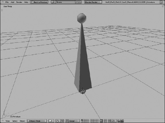
Armature![]() Single Bone. As Figure 11-7 shows, adding an armature creates a single object with a weird shape called an octahedron. Continuing to use the skeleton analogy, that octahedron is referred to as a bone in the armature. The wide end of the bone is referred to as the bone's head or root, and its narrow end is referred to as the bone's tail or tip. Typically, a bone pivots at the head.
Single Bone. As Figure 11-7 shows, adding an armature creates a single object with a weird shape called an octahedron. Continuing to use the skeleton analogy, that octahedron is referred to as a bone in the armature. The wide end of the bone is referred to as the bone's head or root, and its narrow end is referred to as the bone's tail or tip. Typically, a bone pivots at the head.
Figure 11-7: An armature object with a single bone. Woohoo!
Editing armatures
You can take a rather inauspicious single bone armature and do something more interesting with it. Like nearly every other object in Blender, you can edit the armature in more detail by selecting it (right-click) and tabbing into Edit mode. In Edit mode, you can select the sphere at the bone's head, the sphere at the bone's tail, and the bone itself. (Selecting the bone body actually also selects both the head and tail spheres as well.)You can add a new bone to your armature in five ways:
- Extrude: Select either the head or tail of the bone and press E to extrude a new bone from that point. This method is the most common way to add new bones to an armature. If you add a bone by extruding from the tail, you get the additional benefit of having an instant parent-child relationship. The new bone is the child of the one you extruded it from. These bones are linked together, tail to head, and referred to as a bone chain. The Ctrl+left-click extrude shortcut for meshes and curves also works for bones.
- Duplicate: Select the body of the bone you want and press Shift+D to duplicate it and create a new bone with the same dimensions, parent relationships, and constraints.
- Subdivide: Select the body of the bone you want and press W
 Subdivide. You see two bones in the space that the one you selected used to occupy. The cool thing about this option is that it keeps the new bone in the correct parent-child relationship of the bone chain. Also, you can use the Last Operations panel (F6) and do multiple subdivisions.
 - Adding: Press Shift+A while still in Edit mode. A new bone is created with its head at the location of the 3D cursor.
- Skeleton sketching: This somewhat advanced feature is incredibly useful for some of the more complex rigging tasks. If you want to try out skeleton sketching, pop open the 3D View's Properties region, enable the Skeleton Sketching check box, and expand its panel at the bottom of the shelf. The fastest way to see what skeleton sketching does is to enable the Quick Sketching check box. Now, when you left-click and drag your mouse cursor in the 3D View, a red line appears in the view. By simply clicking in the screen, you can draw single straight lines. After you're done drawing, right-click, and Blender generates bones along the line you drew.
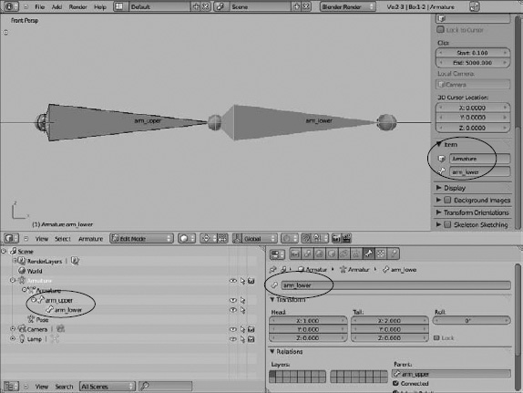
 Armatures can get very complex very quickly, so you should name your bones as you add them. Let me say that again: Name your bones as you add them. The fastest way to name your bones is from the Item panel in the 3D View's Properties region (N) and edit the names of your bones the same way you edit names of other Blender objects. Left-click the name in the Bone field and type the name of a bone that makes sense. Alternatively, you can go to Bone Properties and change the name of your bone from the text field at the top. As an example, if you have a two-bone chain to control a character's arm, you may name one bone arm_upper and the other arm_lower.
Unfortunately, both these techniques can be really slow if you're trying to name a lot of bones at once (because maybe, ahem, you forgot to name your bones as you were adding them). For this hopefully rare case, the Outliner is the best tool for the job. Expand the Armature object to reveal the hierarchy of bones within it. Ctrl+left-click the name of any bone (or any object, for that matter), and you can rename it right there. Figure 11-8 shows the three places where you can name your bones.
Figure 11-8: Three different ways to name your bones.
![]() Blender has a pretty cool way of understanding symmetric rigs, or rigs that have a left side that's identical to the right. For these cases, use a .L and .R suffix on your bone names. So in the previous example, if you're rigging a character with two arms, the bones in the left arm would be named arm_upper.L and arm_lower.L. The right arm bones would be named arm_upper.R and arm_lower.R. This naming convention gives you a couple of advantages, but the one that's most apparent when modeling your rig is the X-Axis Mirror feature.
Blender has a pretty cool way of understanding symmetric rigs, or rigs that have a left side that's identical to the right. For these cases, use a .L and .R suffix on your bone names. So in the previous example, if you're rigging a character with two arms, the bones in the left arm would be named arm_upper.L and arm_lower.L. The right arm bones would be named arm_upper.R and arm_lower.R. This naming convention gives you a couple of advantages, but the one that's most apparent when modeling your rig is the X-Axis Mirror feature.
To understand how symmetric rigs and X-axis mirroring work better, create a new armature at the origin (Shift+S![]() Cursor to Center, Shift+A
Cursor to Center, Shift+A![]() Armature
Armature![]() Single Bone) and follow these steps:
Single Bone) and follow these steps:
- Tab into Edit mode on your armature and change to front view (Numpad 1).
- Select the tail of the single bone and extrude a bone to the right (E).
- Name this bone Bone.R.
- Select the tail of the main, or root, bone again and extrude another new bone, but this time to the left (E).
- Name this bone Bone.L.
- In Tool Shelf (T), enable the X-Axis Mirror check box.
- Select the tail of Bone.R and grab it to move it around (G).
Now, wherever you move the tail of this bone, the tail of Bone.L matches that movement on the other side of the X-axis. You can even extrude (E) a new bone, and a new bone is extruded on both sides of the axis. In this way, X-axis mirroring can speed up the rigging process immensely.
![]() When editing bones, it's a good idea to make visible the mesh for which your rig is intended. This way, you get your proportions correct. A good general rule for placing bones is to think about where the character's real anatomical bones would be located and then use that as a guideline.
When editing bones, it's a good idea to make visible the mesh for which your rig is intended. This way, you get your proportions correct. A good general rule for placing bones is to think about where the character's real anatomical bones would be located and then use that as a guideline.
Parenting bones
One important thing that makes armatures helpful is the notion of how its bones relate to one another. The most important of these relationships is the parent-child relationships between bones. The same hotkeys for parenting and unparenting objects also work with bones, but with a couple additional features. To illustrate the additional features when parenting bones, start a new scene (Ctrl+N), delete the default cube (X), add a new armature object (Shift+A![]() Armature
Armature![]() Single Bone), and then tab into Edit mode. Then follow these steps:
Single Bone), and then tab into Edit mode. Then follow these steps:
- Select the single bone created, duplicate it, and place it somewhere in space (right-click, Shift+D).
- Add the original bone to your selection (Shift+right-click).
- Press Ctrl+P to make the original bone the parent of the duplicate.
You're given two options:
- Connected: This option moves the head of the child bone to the same location as the tail of the parent, creating a bone chain as if you'd created the second bone by extruding it from the first.
- Keep Offset: Choosing this option leaves the child bone in place and draws a dashed relationship line between the two bones. They're not connected, but one still has an influence on the other.
- After you create the parent relationship, select the child bone.
- Clear the parent relationship by pressing Alt+P.
You have another pair of options:
- Clear Parent: This option removes any sort of parent-child relationship this bone has. If the bone was connected to the parent bone, it's now disconnected, and you can move it around freely.
- Disconnect Bone: This option doesn't actually clear the parent relationship. Instead, if your bones are connected, choosing this option maintains the parent-child relationship, but the child bone can move independently of the parent's tip. The bone behaves as if you made the parent by using the Keep Offset option.
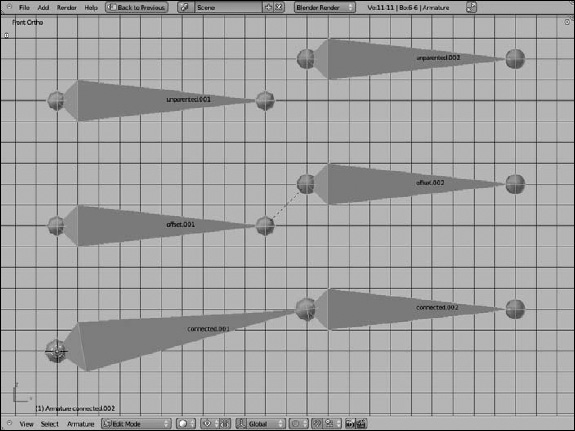
Figure 11-9 shows how two bones in an armature can be related.
Figure 11-9: Bones that are unparented, with an offset parent, and parented with a connection.
![]() Even with bones parented — connected or otherwise — if you rotate the parent bone, the child doesn't rotate with it as you might expect in a typical parent-child relationship. That's because you're still in Edit mode, which is designed mostly for building and modifying the armature's structure. The parent-child relationship actually works in a special mode for armatures called Pose mode. You access this mode by pressing Ctrl+Tab. When you're in Pose mode, if you select individual bones and rotate them, their children rotate with them, as you might expect. From there, you can swap back out to Object mode by pressing Ctrl+Tab again, or you can jump back into Edit mode by just pressing Tab. Chapter 12 has more on working in Pose mode.
Even with bones parented — connected or otherwise — if you rotate the parent bone, the child doesn't rotate with it as you might expect in a typical parent-child relationship. That's because you're still in Edit mode, which is designed mostly for building and modifying the armature's structure. The parent-child relationship actually works in a special mode for armatures called Pose mode. You access this mode by pressing Ctrl+Tab. When you're in Pose mode, if you select individual bones and rotate them, their children rotate with them, as you might expect. From there, you can swap back out to Object mode by pressing Ctrl+Tab again, or you can jump back into Edit mode by just pressing Tab. Chapter 12 has more on working in Pose mode.
Armature properties
When working with armatures, the Properties editor has some sections specific to armatures with options and controls that are incredibly helpful. Select your armature (right-click) and have a look at the Properties editor. In particular, note that the Object Data Properties show an icon of a figure, and you see two additional sets of properties: Bone Properties and Bone Constraints Properties. Figure 11-10 shows the contents of these panels.
Figure 11-10: Armature properties.
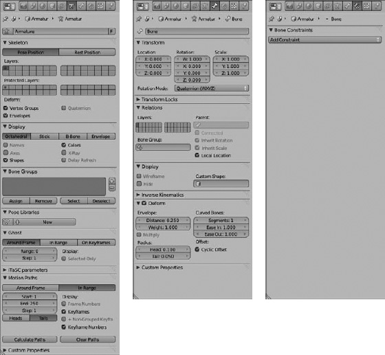
As you may have guessed, Object Data Properties provide options for the Armature overall, while Bone Properties provide options for the currently selected bone. Looking first at the Bone Properties, some options and controls are immediately helpful. The text field at the top lets you rename your bone. The Transform panel gives you precise numeric control over the location of the head and tail of the selected bone, as well as its roll angle, or the orientation of the octahedron between the head and the tail. These controls are exactly the same as the transform controls in the 3D View's Properties region.
In the Relations panel, you can define how the selected bone relates to other bones in the armature. In particular, the Parent field displays the selected bone's current parent, if it has one, and allows you to choose another existing bone as its parent. If you have a parent defined here, the Connected check box beneath it allows you to tell Blender whether it's connected to its parent.
On the left side of the Relations panel are a series of buttons, known as bone layers, which look like the layers buttons in the 3D View's header. Just as you can place objects on layers in Object mode, Blender's armatures have a special set of layers to themselves. The reason is that character rigs can get pretty involved. Using bone layers is a good way to keep the rig logical and organized. Left-click a layer button to assign the bone to it. If you'd like the bone to live on more than one layer, you can Shift+left-click the buttons for those layers.
The options in the various armature-related sections of the Properties editor change a bit between Edit mode (Tab), Object mode, and Pose mode (Ctrl+Tab). What I cover is available in Edit mode and Pose mode.
Two other important sets of controls are in Bone Properties. The first is the Deform panel. Simply put, the check box for this panel is a toggle that tells Blender whether the selected bone can be mapped to the geometry of your mesh. If it is mapped, or weighted, to the mesh, then that bone is considered a deformer. Deformers should have the Deform check box in Bone Properties enabled. Besides deformers, you can also have bones whose purpose is to control the behavior of the deformer bones. These bones are often referred to as control bones. To prevent the control bones from inadvertently influencing your mesh's geometry, you want to make sure that the Deform check box is disabled in Bone Properties.
Back in Object Data Properties, two sets of layer buttons appear in the Skeleton panel. These buttons correspond to the bone layers in Bone Properties. The layer buttons under the Layers label control which layers the armature is actually displaying in the 3D View. The layer buttons under the Protected Layers label have an effect only if you're linking your rig into a separate scene file. That topic is a bit more advanced than what this book covers, so I leave it at that for now.
![]() One option I like to enable in this panel is the Quaternion check box. This option is more relevant after you begin animating with your rig, but enabling it makes the armature deform the mesh assigned to it a lot more cleanly than if it's disabled. Occasionally, enabling the Quaternion check box can cause deformation artifacts in your character mesh, but that is usually pretty rare.
One option I like to enable in this panel is the Quaternion check box. This option is more relevant after you begin animating with your rig, but enabling it makes the armature deform the mesh assigned to it a lot more cleanly than if it's disabled. Occasionally, enabling the Quaternion check box can cause deformation artifacts in your character mesh, but that is usually pretty rare.
The Display panel contains a set of buttons for controlling how bones in the armature are displayed:
- Bone types: You can enable only one of these four buttons at any point in time. Note, however, that even though the bone type may not be drawn in the 3D View, its influences are still valid. That is, even if you're displaying Stick bones, they still control the same vertices within the range of the Envelope bones. Figure 11-11 shows examples of each of these bone types.
- Octahedral: The default bone type, the octahedral shape is great for building a rig because it shows which way a bone points as well as its roll angle.
- Stick: This type draws the bones as a thin stick. I like to animate with my bones in this type so that they stay out of my way.
Figure 11-11: The different types of bones in Blender from top to bottom: octahedral, stick, b-bone, and envelope.

- B-Bone: B-bones are drawn as boxes. The interesting thing, though, is that b-bones can be dynamically subdivided and treated as simple Bézier curves. To increase a bone's subdivisions, select the bone and switch to the Deform panel in Bone Properties. In this panel, increase the Segments value, which makes the deformation from one bone to the next much smoother. The chain on the cover of this book was rigged using b-bones. Even if you don't display the b-bone type, Blender still pays attention to the Segments value. So if your character deforms in an unexpected way, you may want to check the Segments value in Bone Properties.
- Envelope: This type draws the bones with a scalable sphere at each end and a tube for the bone body. Vertices on your mesh that are within the influence area of these bones will have their locations influenced by them. Ctrl+Alt+S increases the bone's range.
- Extra display options: You can enable all, one, or none of these controls in any combination you desire.
- Names: This control displays the name of each bone in the 3D View. Names can make selecting bones and defining constraints much easier.
- Axes: This control displays the center axis of the bones. The Axes check box is helpful for understanding the bones' true roll angle.
- Shapes: To help communicate a bone's purpose to the animator, you can display any bone in Blender as any object in your scene. While in Pose mode, select a bone and go to the Display panel in Bone Properties. There, you can define the object you want as your bone shape by choosing it from the Custom Shape field. With the Shapes check box enabled in Object Data Properties, the bone is displayed as your chosen object while in Pose mode.
- Colors: To help organize bones in an armature for an animator, you can actually define custom colors for bones by using bone groups (see the section “Making the rig more user friendly”). Set all facial controls to blue, or the left side of the armature in red. Enable this check box so that you can make use of those colors.
- X-Ray: The X-Ray check box in this panel does the same thing that the X-Ray check box in Object Properties does. It allows you to see the bone in the 3D View, even if it's technically inside or behind another object. Enabling this feature makes your bones much easier to select when rigging or animating.
- Delay Refresh: Rigs by themselves can be very complex. After they have a mesh assigned to them, the system becomes even more complex — sometimes to the point that slower computers can't keep up and perform with any reasonable response. In this type of scenario, enabling this check box may be beneficial because it prevents Blender from trying to calculate how your mesh deforms while you modify a pose on your rig, delaying that calculation until after you finish grabbing, scaling, or rotating a bone.
Putting skin on your skeleton
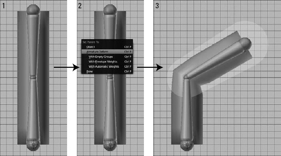
Armatures and bones are pretty interesting, but they do you no good if they don't actually deform your mesh. When you create your own rig, and Ctrl+Tab to Pose mode, you can grab, rotate, and scale bones, but the moving bones have no influence whatsoever on your mesh. What you need to do is bind the vertices of the mesh to specific bones in your armature. This binding process is commonly referred to as skinning. Blender has two primary ways of skinning: envelopes and vertex groups.
Quick-and-dirty skinning with envelopes
Envelopes are the quickest way to get a mesh's vertices to be controlled by the armature. You don't have to create anything extra: It's just a simple parenting operation that seals the deal. To use envelopes to control your mesh, use the following steps:
- In Object mode or Pose mode, select the mesh (right-click) and then add the armature to your selection (Shift+right-click).
- Make the armature the parent of the mesh (Ctrl+P).
Choose Armature Deform from the menu that appears. Upon completion, your mesh is a child of the armature object, and it also now has an Armature modifier applied. The modifier is what allows the armature to deform your mesh. Without the modifier, it's just a simple parenting.
When you Ctrl+Tab into Pose mode on your armature, the mesh is now under its influence.
- Go to Object Data Properties and enable the Envelope bone type.
This step reveals exactly where the influence of your envelopes lies.
- If some part of your mesh isn't under the influence of an envelope, tab into Edit mode and edit its size and influence.
(Actually, if you just want to edit the influence, you can do so directly with the Ctrl+Alt+S hotkey combination.)
Figure 11-12 illustrates envelopes in action.
Envelopes are great for quickly roughing out a rig and testing it on your mesh, but for detailed deformations, they aren't ideal. Where the influence of multiple envelopes overlap can be particularly problematic, and there's a good tendency for envelope-based rigs to have characters pinch a bit at their joints. For these cases, a more detailed approach is necessary.
Figure 11-12: Using envelopes to control your armature's influence over the mesh.
![]() That said, using envelopes in your armature does give you one distinct control that you can't have with armatures otherwise. You can actually use an armature with envelopes to control the deformation of curves and surfaces. So long as a control point is within the influence space of a bone's envelope, you can modify it and therefore animate it with the armature.
That said, using envelopes in your armature does give you one distinct control that you can't have with armatures otherwise. You can actually use an armature with envelopes to control the deformation of curves and surfaces. So long as a control point is within the influence space of a bone's envelope, you can modify it and therefore animate it with the armature.
Assigning weights to vertices
So if envelopes are the imprecise way of controlling your mesh, what's the precise way? The answer is vertex groups. A vertex group is basically what it sounds like — a set of vertices that have been assigned to a named group.
In many ways, a vertex group is a lot like a material slot (see Chapter 7). Besides the fact that vertex groups don't deal with materials, vertex groups have a couple of distinctions that set them apart from material slots. First of all, vertex groups aren't mutually exclusive. Any vertex may belong to any number of vertex groups that you define.
The other distinction is that you can give a vertex a weight, or a numerical value that indicates how much that particular vertex is influenced or dedicated to the vertex group. A weight of 1.0 means that the vertex is fully dedicated to that group, whereas a weight of 0 means that although the vertex is technically part of the group, it may as well not be.
One thing to note: Vertex groups need to have the exact name of the bones that control them. So if you have a bone called pelvis, you need a corresponding vertex group with the same name. The vertices assigned to that group then have their position influenced by the location, rotation, and scale of the pelvis bone, tempered by the vertices' individual weights.
To adjust the assignments and weights of vertices in their respective vertex groups, you can use the Vertex Groups panel in Object Data Properties for your selected mesh. You create a new group with the Plus (+) button to the right of the list box. To select the vertices that you want to assign to the group, you need to tab into Edit mode. With the vertices selected in Edit mode, you can adjust the value in the Weight slider and then assign them to the vertex group by left-clicking the Assign button.
![]() If you don't see the Assign button or Weight slider in the Vertex Groups panel, then you're not in Edit mode. Tab into Edit mode and those controls should appear for you.
If you don't see the Assign button or Weight slider in the Vertex Groups panel, then you're not in Edit mode. Tab into Edit mode and those controls should appear for you.
Something to note about vertex weights is that, when used for armatures, they are normalized to 1.000. That is, a vertex can be a member of two vertex groups and have a weight of 1.000 for both. In these cases, Blender adjusts the weights internally so that they add up to 1.000. So in my example, that double-grouped vertex behaves like it has a weight of 0.500 on both groups.
Of course, on a complex armature, this process of creating vertex groups and painstakingly assigning weights to each vertex can get excessively tedious. Fortunately, Blender has a couple tools to make things less painful. First of all, you don't have to create all the vertex groups by yourself. Refer to the preceding section on the process of skinning with envelopes. By parenting the mesh to the armature there, you're presented with a few options. For using envelopes only, you choose Ctrl+P![]() Armature Deform. However, the other options give you a lot of power when you use vertex groups:
Armature Deform. However, the other options give you a lot of power when you use vertex groups:
- Object: This option is just a simple parenting operation. Your whole mesh becomes a child of the armature object, just as if you'd parented it to another mesh. No modifier is applied to your mesh at all.
- Armature Deform: As in the envelope skinning example of the preceding section, this option doesn't create any vertex groups, thereby ensuring that the mesh is only influenced by the bone envelopes.
- With Empty Groups: This option creates vertex groups for you using the names of all the bones with the Deform check box enabled in Bone Properties. However, it doesn't automatically assign any vertices to any of those groups. Use this option if you want to manually assign weights. Without assigning any weights, the default behavior is to be controlled only by bone envelopes.
- With Envelope Weights: This option is a bit of a compromise. It first creates the vertex groups based on the bones with their Deform option turned on. Then it looks at the influence area of the bone envelope and uses that to assign vertices to each vertex group, with their weights varied accordingly. The advantage of this option is that it gets you weighted vertices. The downside, though, is that if the influence area of your envelopes isn't set up well, the weight assignment can look messy.
- With Automatic Weights: This is my favorite option to use. It works like the With Envelope Weights option, but instead of using the influence area of the bone envelopes to determine weights, it uses a more complex process that generally results in better vertex assignments and weights.
- Bone: This is a simple parenting operation like the Object option. No Armature modifier is applied to your mesh. The only difference here is that rather than parent your mesh to the whole armature object, this option allows you to parent your object to a single bone.
Regardless of which option you choose, you'll probably still have to go in and manually tweak the weights of the vertices in each vertex group. Trying to do those tweaks just from the Vertex Groups panel can be pretty painful. Fortunately, there is Weight Paint mode. This mode is almost exactly like Vertex Paint mode (see Chapter 7), except that rather than painting color on the mesh, you're painting the weight assignment to a specified vertex group.
To access Weight Paint mode, select the mesh (right-click) and press Ctrl+Tab. Alternatively, you can choose Weight Paint mode from the Mode menu in the 3D View's header. Even if you don't intend to paint weights, Weight Paint mode is a great way to see how the weights were assigned by Blender if you used the automatic method.
The way that weights are visualized is kind of like a thermal map where red is the hottest value and blue is the coldest value. Extending this logic to work with bone weights, vertices that are painted red have a weight of 1.0, whereas vertices painted blue are either not assigned to the vertex group or have a weight of zero. The 50 percent weight color is bright green.
![]() If the thermal map color styling isn't your thing (as can be the case if you're colorblind), you can define your own weight paint color range using the ramp editor in the bottom right of the System section of Blender's User Preferences (Ctrl+Alt+U). When in Weight Paint mode, you get a bunch of painting panels in the Tool Shelf, as shown in Figure 11-13. With a few minor exceptions, these controls are identical to the ones used in Vertex Paint mode.
If the thermal map color styling isn't your thing (as can be the case if you're colorblind), you can define your own weight paint color range using the ramp editor in the bottom right of the System section of Blender's User Preferences (Ctrl+Alt+U). When in Weight Paint mode, you get a bunch of painting panels in the Tool Shelf, as shown in Figure 11-13. With a few minor exceptions, these controls are identical to the ones used in Vertex Paint mode.
![]() When weight painting, it's often useful to enable the Wire check box in the Display panel of Object Properties. Enabling this check box overlays the mesh's wireframe on it. Seeing the wireframe is especially helpful when weight painting because it helps you see where the actual vertices on the mesh are. That way, you're not just painting in empty space where no vertices exist. The only slight hiccup is if you're painting planar vertices, or vertices that all share the same plane. In this particular case, Blender tries to simplify the wireframe overlay. While that simplification may be nice in general, it can be problematic when painting. To get around that obstacle, enable the All Edges check box in the Display panel in the 3D View's Properties region (N).
When weight painting, it's often useful to enable the Wire check box in the Display panel of Object Properties. Enabling this check box overlays the mesh's wireframe on it. Seeing the wireframe is especially helpful when weight painting because it helps you see where the actual vertices on the mesh are. That way, you're not just painting in empty space where no vertices exist. The only slight hiccup is if you're painting planar vertices, or vertices that all share the same plane. In this particular case, Blender tries to simplify the wireframe overlay. While that simplification may be nice in general, it can be problematic when painting. To get around that obstacle, enable the All Edges check box in the Display panel in the 3D View's Properties region (N).
Figure 11-13: The painting panels in the Tool Shelf when Weight Paint mode is activated.

A handy feature in the Tool Shelf while weight painting is the X-Mirror check box in the Options panel. X-Mirror can literally cut your weight painting time in half. When you enable this check box, Blender takes advantage of the left/right naming convention discussed earlier in the “Editing armatures” section of this chapter. So if you're tweaking the vertex weights on the left leg, Blender automatically updates the weights for the corresponding bone on the right leg so that they match. If that ain't cool, I don't know what is.
The actual process of weight painting is nearly identical to using vertex paint. However, you need to pay attention to one more thing with weight painting: the need to tell Blender which vertex group you're painting. You can do so in two ways. The slow way, you already know: Select the group from the list box in the Vertex Groups panel in your mesh's Object Data Properties.
Of course, the kind Blender developers have provided a faster way: Select (right-click) the bone that you want to paint weights for, and Blender automatically activates the corresponding vertex group and allows you to paint. As an added bonus, you can test your weights on the fly by grabbing, rotating, or scaling the selected bone while you're still in Weight Paint mode.
Because weight paint relies so much on color, I highly recommend you look at the full-color version of a simple mesh in Weight Paint mode in this book's color insert.
![]() If you choose to use vertex groups, you have something else to decide. Have a look at the Armature modifier on your mesh. Under the Bind To label are two check boxes: Vertex Groups and Bone Envelopes. With both enabled, the mesh is influenced by both vertex groups, as well as the bone envelopes from your armature. This double influence can be useful in some instances, but I tend to prefer to work with just one or the other. And if I create vertex groups and assign weights to vertices, I generally disable the Bone Envelopes check box. Your rigging needs may be different, but this setup works for me because this way I know that the only reason a vertex is deforming improperly is that I didn't assign its weight properly. I don't have to concern myself with the influence of the bone's envelope.
If you choose to use vertex groups, you have something else to decide. Have a look at the Armature modifier on your mesh. Under the Bind To label are two check boxes: Vertex Groups and Bone Envelopes. With both enabled, the mesh is influenced by both vertex groups, as well as the bone envelopes from your armature. This double influence can be useful in some instances, but I tend to prefer to work with just one or the other. And if I create vertex groups and assign weights to vertices, I generally disable the Bone Envelopes check box. Your rigging needs may be different, but this setup works for me because this way I know that the only reason a vertex is deforming improperly is that I didn't assign its weight properly. I don't have to concern myself with the influence of the bone's envelope.