Making Changes by Using Edit Mode
Moving primitive objects around is fun and all, but you're interested in getting in there and completely changing these objects to match your vision. You want to do 3D modeling. Well, you're in the right place. This section introduces you to Edit mode, a concept that's deeply embedded throughout Blender for editing objects. Even though this section is focused mostly on polygon modeling, also called mesh editing, most of the same principles apply for editing curves, surfaces, armatures, and even text.
 When you understand how Blender thinks, figuring out unknown parts of the program is much easier.
Distinguishing between Object mode and Edit mode
In Chapter 3, you do everything in Object mode. As its name indicates, Object mode is where you work with whole objects. However, Object mode isn't very useful for actually changing the internal structure of your object. For example, select (right-click) the cube in the default scene. You know that you can turn it into a more rectangular shape by scaling it along one of the axes. But what if you want to turn the cube into a pyramid? You need to modify the actual components that make up the cube. These changes are made by entering Edit mode.
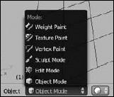
You can get to Edit mode in one of two ways: with the mouse or with a hotkey. To use the mouse method, left-click the Object Mode button in the 3D View's header. From the pop-up menu that appears, select Edit Mode (see Figure 4-1). Be aware that if you're working with an object other than a mesh, such as an armature, the contents of this menu may vary slightly to relate more to that object. However, with the exception of Empties (see Chapter 10), all objects have an Edit mode.
Figure 4-1: The Mode button allows you to switch between Object mode and Edit mode for a selected object.
![]() Of course, Blender also has a hotkey to enter Edit mode. Actually, technically speaking, the hotkey toggles you between Object mode and Edit mode. Pressing Tab is the preferred way to switch between modes in Blender, and it's used so frequently that Blender users often use Tab as a verb and say they're tabbing into Edit mode or Object mode. This language is something you come across fairly often in Blender user forums and in some of Blender's online documentation.
Of course, Blender also has a hotkey to enter Edit mode. Actually, technically speaking, the hotkey toggles you between Object mode and Edit mode. Pressing Tab is the preferred way to switch between modes in Blender, and it's used so frequently that Blender users often use Tab as a verb and say they're tabbing into Edit mode or Object mode. This language is something you come across fairly often in Blender user forums and in some of Blender's online documentation.
Selecting vertices, edges, and faces
After you tab into Edit mode, the cube changes color and points form at each of the cube's corners. Each point is a vertex. The line that forms between two vertices is an edge. A face in Blender is a polygon that has been formed by three or four connecting edges.
Currently, faces in Blender are limited to only three-sided and four-sided polygons, often referred to as tris (pronounced like tries) and quads. In the not-to-distant feature, Blender — like many other programs — will support something called an n-gon that can have a virtually limitless number of sides. However, at this time, only some development versions of Blender have n-gon functionality. The current release is still limited to tris and quads. This situation isn't completely horrible, however, because you can still do a lot with just three- and four-sided faces. In fact, most detailed character models are made almost completely with quads and an occasional triangle, and all 3D geometry is reduced to triangles when it gets to your computer hardware. If you're interested, you can find more detailed information about Bmesh and n-gons in the “A word on Bmesh and n-gons” sidebar, later in this chapter
For polygon editing, you can use three different types of Edit modes, sometimes called selection modes: Vertex Select, Edge Select, and Face Select. By default, the first time you tab into Edit mode, you're in Vertex Select mode.
Two visual cues in the Blender interface clue you in to what selection mode you're using. First, for Vertex Select mode, you can see the individual vertices in the mesh. Second, as Figure 4-2 shows, three new buttons appear in the 3D View's header when you're in Edit mode. The button on the left (it has an icon of a cube with an orange dot over one corner) is enabled, indicating that you're in Vertex Select mode.
Figure 4-2: The Edit mode Select buttons.
![]()
To the right of the Vertex Select button is a button displaying an icon of a cube with a highlighted edge. Click this button to activate Edge Select mode. When you do, the vertices are no longer visible on your mesh. Clicking the last button in this block, which has an icon of a cube with one side marked in orange, activates Face Select mode. When Face Select mode is active, vertices aren't visible, and each polygon in your mesh has a square dot in the center of it.
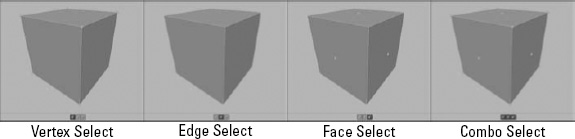
Now, you may notice that these buttons are blocked together, kind of like the 3D manipulator buttons. So, as with the manipulator, can you simultaneously activate multiple modes? Absolutely! Simply Shift+left-click the Select mode buttons to get this function. Some Blender modelers like to have Vertex Select and Edge Select modes active at the same time to speed up their workflow. This combination selection mode gives them immediate control at the vertex and edge level, and you can easily select the faces by using Blender's Lasso select (Ctrl+left-click+drag) across two edges. Figure 4-3 shows the default cube in each of the select modes, as well as a Combo Select mode.
Figure 4-3: Vertex Select, Edge Select, Face Select, and Combo Select modes.
Of course, you can also use a hotkey sequence to access the various select modes. While you're in Edit mode, if you press Ctrl+Tab, you see a menu that lets you switch between modes. This menu doesn't let you set multiple modes; for combo selection, you still have to use the buttons in the 3D View's header.
Also, by default, the first time you tab into Edit mode, all vertices/edges/faces are selected. Selecting things in Edit mode works just like selecting anywhere else:
- Right-click any vertex to select it.
- Select and deselect multiple vertices by Shift+right-clicking them.
- Select large groups of vertices by using the Border Select tool (B), Circle Select (C), or Lasso Select (Ctrl+left-click+drag).
- In Border and Circle Select, left-click and drag your mouse cursor to add to your selection. For Border Select, this action draws a box to define a selection area.
- Circle Select is sometimes called Brush Select because selection is like painting. Any vertices that you run your mouse cursor over while holding down the left mouse button are selected.
- Middle-click and drag to subtract from your selection and right-click or press Esc to exit Border or Circle Select.
- To use Lasso Select functionality, Ctrl+left-click and drag your mouse cursor around the vertices you want to select. Anything within that selection region is added to your selection.
And, of course, all these selection tools work in Edge and Face Select modes, as well as in Object mode. Figure 4-4 shows what the various selection tools look like when in use.
Figure 4-4: Border Select, Circle Select, and Lasso Select.

![]() If you want to select everything (in Object mode, all objects; in Edit mode, all vertices in the active object), you can do so by pressing A. The A hotkey is a toggle, so anything previously selected when you press A is deselected. However, if nothing is previously selected, pressing A selects everything. Using this hotkey, you'll find yourself pressing A until you have either everything or nothing selected.
If you want to select everything (in Object mode, all objects; in Edit mode, all vertices in the active object), you can do so by pressing A. The A hotkey is a toggle, so anything previously selected when you press A is deselected. However, if nothing is previously selected, pressing A selects everything. Using this hotkey, you'll find yourself pressing A until you have either everything or nothing selected.
If you're using Blender's default settings, you can't see through your model. You can't select the vertices, edges, and faces on the back side of the model unless you orbit the 3D View to see those vertices or drop into the wireframe viewport shading setting. (Toggle between wireframe and solid by pressing Z.) On occasion, however, you may find it useful to see (and select) those hidden vertices while in solid viewport shading. To do so, click the Limit Selection to Visible button, sometimes referred to as the Occlude Background Geometry button. Located to the right of the Selection Modes block in the 3D View's header, this button has an icon of a cube with white highlighted vertices on it. (Refer to Figure 4-2.) By default, the Occlude Background Geometry button is enabled, but you can click this button to reveal the vertices, edges, and faces on the back of your model. The hiding of those rear vertices is often referred to as backface culling, and it's incredibly useful when you're working with complex models. I recommend that you keep it enabled and just temporarily switch to wireframe viewport shading (Z) if you need to quickly see or select those backface vertices.
Working with linked vertices
Another handy way to select things in Edit mode is by selecting linked vertices. Linked vertices are a set of vertices within a mesh that are connected by edges. In order to understand linked vertices better, go through the following steps:
- Select (right-click) your default cube in Blender and tab into Edit mode.
All the vertices are selected. If not, press A until they are.
- With all the vertices selected, press Shift+D or choose Add
 Duplicate from the Tool Shelf or MeshAdd Duplicate from the 3D View's header to duplicate your selection.
Blender creates a copy of your selection and automatically switches to grab mode, allowing you to move the duplicate set of vertices, edges, and faces immediately.
- Use your mouse to move your new cube off the original and confirm your placement by left-clicking a second time or pressing Enter.
None of the vertices in the original cube are selected. Each cube represents a set of linked vertices. So what if you want to select all the vertices in that cube, too? Sure, you can use the Border, Circle, or Lasso Select tools, but on complex meshes, these tools can get cumbersome. Instead, move to the next step.
- Place your mouse cursor near any vertex in the original cube and press L.
Blam! All the vertices in both of your cubes are selected.
Of course, the natural next question is, “How do I deselect linked vertices?” That's just as easy. Place your mouse cursor near any vertex on the duplicate cube you created and press Shift+L. All vertices connected to the one near your mouse cursor are deselected. I've found myself using L and Shift+L pretty heavily when trying to place teeth in a mouth I've modeled. These hotkeys are very handy.
Quite a few more selection options are available to you when working with meshes. I describe these selection methods in detail in Chapter 5.
While you're in Edit mode, you can work only with the current active object. You can't select and manipulate other objects while you're in Edit mode.
Still Blender's No. 1 modeling tool: Extrude
Besides transform operations (see Chapter 3), the most commonly used modeling tool in Blender is the Extrude function. In meatspace, extrusion is a process whereby some material is pushed through a shaped hole of some sort. When you were a kid, did you ever cut out a shape in cardboard and force clay or mud or Play-Doh through it? If so, you were extruding. If not, you certainly missed out on a good solid five to ten minutes of fun.
A longstanding criticism of Blender over the years is a relative lack of advanced mesh-editing features and tools. Some examples of such tools include per-edge beveling, clean boolean operations, and the notorious n-gon.
The reason Blender carried these limitations for so long has to do with its reliance on older code for Blender's mesh structures, called EditMesh among the Blender developers. In order to support these other powerful features, the EditMesh structure needed to be refactored. For that reason, the Bmesh (short for Blender Mesh) project was launched. It's been slowly developing over the years, with only the attention of two developers working on it, and is slated to be included after the Blender 2.5 series finishes development and Version 2.6 is released. Not only does the Bmesh structure provide users with more powerful tools, but it's also more robust and may perform faster than the old EditMesh structure in some specific cases.
In 3D, extrusion follows a similar concept, except you don't have to create the hole to extrude through. Instead, that shape is determined by your selection and you can extend that selection in any direction. Use the following steps to extrude:
- Select the object you want to edit by right-clicking it.
- Tab into Edit mode.
- Select the vertices, edges, or faces you want to extrude.
Use any of the selection methods listed in the previous section.
- Extrude your selection in one of several ways:
- Use the E hotkey.
- Left-click AddExtrude Region in the Tool Shelf.
- Choose MeshExtrude Region from the menu in the 3D View's header.
After you extrude your selection, Blender automatically puts you into grab mode on the newly extruded parts.
Now, if you extrude a polygon, your new extrusion is constrained to move only along its normal. If you don't want this constrained behavior, middle-click your mouse (without moving it) and the constraint is removed, allowing you to freely move your extrusion around.
If you extrude an edge, your extrusion is constrained to a plane perpendicular to your newly extruded edge. If you extrude a single vertex, you're in a free extrude mode that's completely unconstrained. In order to use constraints in this case, you need to use the coordinate system constraint hotkeys described in Chapter 3.
Modeling organically with the Proportional Edit tool
Often, when you're modeling organic objects or objects with smoothly curved surfaces, such as characters, creatures, or sports cars, you may find yourself pushing and pulling a bunch of vertices to obtain that smooth surface. You can simplify this process by using Blender's Proportional Edit Tool (PET).
If you come from another 3D package, you might recognize PET as being similar to the soft select feature. You activate PET by left-clicking the PET button, which looks like two gray concentric circles in the 3D View's header. The hotkey for this operation is O. Now when you perform a transform operation, a circle appears around your selection. Your transformation influences any vertices that are within this circle with a gradual falloff.
You can adjust the influence of the PET by scrolling your mouse wheel or pressing Alt+Numpad Plus (+) and Alt+Numpad Minus (–). Additionally, you can control how gradual the falloff is by left-clicking the button with the curve icon next to the PET button in the 3D View's header or by cycling through the options by pressing Shift+0.
PET has one more useful option. On complex meshes, you may want to use PET on one set of vertices that are connected to one another, but not to other nearby vertices in the same mesh. For example, say that you've modeled a character and her hand is at her side near her leg, and you'd like to smoothly edit her hand and pull it away from the leg without having to gradually adjust the vertices of the arm. PET is the perfect tool for this job. However, when you try to use PET, other leg vertices are within the PET's influence, and you end up moving those unintentionally. Wouldn't it be great if the PET could understand that you only want to move the hand? Well, I have good news: It can! Click the PET button in the 3D View header and select Connected or press Alt+O. The Connected option for PET only adjusts vertices that are connected to each other within its influence area. Neat, huh?
The selected orientation in the Coordinate Orientation menu is active even if you're transforming with hotkeys. So if you set that menu to the Normal orientation, you can press Z![]() Z, and your extruded region is constrained to its face. (Just pressing Z once constrains it to the global Z-axis rather than the face's normal.)
Z, and your extruded region is constrained to its face. (Just pressing Z once constrains it to the global Z-axis rather than the face's normal.)
 There are advantages and disadvantages to Blender's extrude function leaping directly into grab mode. The advantages are that you have all the transform functionality, such as axis-locking, snapping, and numerical input immediately available to you. The disadvantage is that, because of this autograb behavior, if you cancel the operation by right-clicking or pressing Esc, the newly extruded vertices, edges, or faces are still there, just located in exactly the same place as the vertices, edges, or faces that they originated from.
For this reason, if you cancel an extrude operation, make sure that your duplicate vertices, called doubles, are no longer there. A quick way to check is to press G after you cancel your extrusion. If it looks like you're extruding again, you have doubles.
You can get rid of doubles in a variety of ways:
- If you still have the doubles selected, delete them. You can activate the delete operation with hotkeys (X or Del), clicking RemoveDelete in the Tool Shelf, or by going to MeshDelete in the 3D View's header. You see a menu where you decide what elements of the mesh you want to delete. In this case, you choose Vertices. The disadvantage of this method is that it also removes the faces created by those vertices.
- If the canceled extrusion operation was the last thing you did, undo it by pressing Ctrl+Z. This solution is probably the quickest.
- If you're unsure whether you have doubles from previous canceled extrusions, use Blender's special Remove Doubles function:
- In Edit Mode, select all by choosing SelectSelect/Deselect All from the 3D View's header or pressing A until all vertices are selected.
- Press WRemove Doubles, and Blender removes all doubles from your mesh.
You can find this option in Mesh
VerticesRemove Doubles in the 3D View's header, as well as the Tool Shelf (RemoveRemove Doubles).
- In Edit Mode, select all by choosing Select
If you look in the Mesh menu of the 3D View, you have more than one Extrude option. A second Extrude operation, called Extrude Individual (Shift+E), works, depending on which selection mode you chose. If you're in Face Select mode, then the Extrude Individual operation extrudes each face you selected along its independent normal. Likewise, if you're in Edge Select mode, Extrude Individual extrudes each edge you selected independently of one another. And the same principle works on vertices if you're in Vertex Select mode and choose Extrude Individual.
When you're modeling, the most common type of extrusion you want is related to what you selected. For example, if you want to extrude an edge, you select that edge, or if you select a group of faces, chances are good that you want to extrude that as a region. As expected, Blender has shortcuts for these common modeling tasks.
To perform a quick extrusion:
- Select your object and tab into Edit mode.
- Select the vertices, edges, or faces you want to extrude.
- Ctrl+left-click where you'd like the extrusion to end.
Blender automatically decides what kind of extrusion you want and extrudes your selection right where you'd like. Working this way is particularly useful when you're doing a series of multiple extrusions, one right after the other, such as when you're roughing out a shape by “drawing” with vertices or edges.
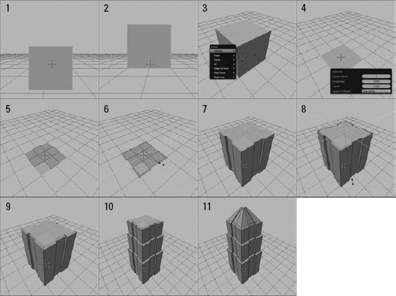
Creating a simple model with Extrude
Although Ctrl+left-clicking for quick extrusion is convenient for creating rough models to start with, extruding with the E key certainly has workflow benefits. The biggest benefit is the quick access to your other transform tools. To illustrate this benefit, use the following steps to model a skyscraper from a single plane:
- Open Blender and tab into Edit mode on the default cube.
- Change to right-side view.
You can do so by pressing Numpad 3 or going to View
Right from the 3D View's header. - Translate everything by 1 unit in the positive Z direction (GZ1Enter).
- Orbit (middle-click+drag) the 3D View so that you can get a good view of the top face of the cube.
- Switch to Face Select mode (Ctrl+TabFaces).
- Select (right-click) the topmost face of the cube and delete it (XVertices).
- Select all (A) and perform a multisubdivide with two cuts.
Use W
Subdivide, AddSubdivide from the Tool Shelf, or MeshEdgesSubdivide from the 3D View's menu. This step creates a single subdivision cut. Increase the number of subdivisions by going to the Last Operator panel at the bottom of the Tool Shelf or pressing F6 and increasing the Number of Cuts value to 2. - Switch to Edge Select mode (Ctrl+TabEdges).
- Select the edges that form the corners of the plane.
Using regular right-clicking, Circle Select (C), or Lasso Select (Ctrl+left-click+drag) works best for this step.
- Extrude these edges and scale them by 1.1 in the XY-plane (ESShift+Z1.1Enter).
- Select all (AA).
- Extrude the region along the global Z-axis (E).
Your extrusion is constrained along the direction of the region's normal. Fortunately, because of the way you're working, that normal coincides with the global Z-axis. The height of this level can be whatever you like. I extruded mine by 3 units.
- With the region still selected, extrude again, but scale the region by 0.9 in the XY-plane (ESShift+Z0.9Enter).
- Translate this new region along the Z-axis by 0.1 units (GZ0.1Enter).
- Perform Steps 12 through 14 as many times as you'd like to get the skyscraper to your desired height.
I gave mine three layers.
- On your last extruded region, scale the selection in the XY-plane to a generally pyramid-shaped peak (SShift+Z).
- Tab back into Object mode and behold the awesome beauty of your skyscraper!
Figure 4-5 shows an illustration of the major steps in this process.
![]() Going through this process, notice how immediately after executing the extrude operation, you can scale the extrusion to create insets and outsets to grow your building from. Using extrusion with your transform tools in this manner gives you an immense amount of speed and flexibility when modeling.
Going through this process, notice how immediately after executing the extrude operation, you can scale the extrusion to create insets and outsets to grow your building from. Using extrusion with your transform tools in this manner gives you an immense amount of speed and flexibility when modeling.
![]() Prior to Blender 2.5, PET worked only while you were in Edit mode. Now, PET works in Object mode as well. This capability can be really handy, but it can sometimes yield undesirable results if you want to use PET only while in Edit mode. For this reason, double-check your 3D View's header before performing a transformation to see whether PET is enabled.
Prior to Blender 2.5, PET worked only while you were in Edit mode. Now, PET works in Object mode as well. This capability can be really handy, but it can sometimes yield undesirable results if you want to use PET only while in Edit mode. For this reason, double-check your 3D View's header before performing a transformation to see whether PET is enabled.
Figure 4-5: Modeling a skyscraper from a single plane.