
Working with the Node-Based Compositor
Compositing is the process of mixing multiple visual assets to create a single image or sequence of images. By this definition, you may notice that technically Blender's VSE qualifies as a sort of compositor because you can stack strips over each other in channels and blend them together with effects and transitions. Although this statement is true, the VSE is nowhere near as powerful as the Node Compositor is for mixing videos, images, and other graphics together.
![]() As designed, the VSE is intended for working with multiple shots, scenes, images, or clips of video. It's also meant to play back in real time (or as near to that as possible). In contrast, the Compositor is intended for working with a single shot, and it's most certainly not meant for working in real time. There is a little bit of overlap in the functionality of these two parts of Blender, but depending on the task at hand, one is more suitable than the other.
As designed, the VSE is intended for working with multiple shots, scenes, images, or clips of video. It's also meant to play back in real time (or as near to that as possible). In contrast, the Compositor is intended for working with a single shot, and it's most certainly not meant for working in real time. There is a little bit of overlap in the functionality of these two parts of Blender, but depending on the task at hand, one is more suitable than the other.
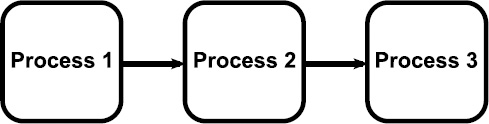
What makes the Node Compositor so powerful? Well, it's in the name: nodes. One of the best ways to understand the power of nodes is to imagine an assembly line. In an assembly line, each step in the process depends on the step immediately preceding it and feeds directly into the following step. This methodology is similar to the layer-based approach used in many image manipulation programs like Photoshop and GIMP. Each layer has exactly one input from the previous layer and one output to the following one. Figure 15-5 illustrates this idea.
Figure 15-5: An assembly line approach, like the layers in GIMP or Photoshop.
That approach works well, but you can enhance the assembly line a bit. Say that some steps produce parts that can go to more than one subsequent step, and that other steps can take parts from two or more earlier steps and make something new. And take it a bit farther by saying that you can duplicate groups of these steps and integrate them easily to other parts of the line. You then have an assembly network like that depicted in Figure 15-6. This networklike approach is what you can do with nodes.
Figure 15-6: Turning a simple assembly line into a complex assembly network.

Understanding the benefits of rendering in passes
Before taking full advantages of nodes, it's worthwhile to take a quick moment and understand what it means to render in passes. Assume for a moment that you animated a character walking into a room and falling down. The room is pretty detailed, so it takes a fairly long time for your computer to render each frame. However, because the camera doesn't move, you can really render the room just once. So if you render your character with a transparent background, you can superimpose the character on just the still image of the room, effectively cutting your render time in half (or less)!
That's the basics of rendering in passes. The preceding example had two passes, one for the room and one for the character. However, you can have many more passes with more detailed content. For example, if you want to, you can have a render pass that consists of just the shadows in the image. You can take that pass and adjust it to make all the shadows slightly blue. Or you can isolate a character while she's walking through a gray, blurry scene.
Another thing to understand for compositing 3D scenes is the concept of Z-depth. Basically, Z-depth is the representation of the distance that an object is from the camera, along the camera's local Z-axis. Z-depth is used quite often in compositing. The compositor can use this Z-depth to make an object look like it fits in a scene even though it was never rendered with it.
To do render passes in Blender, you use render layers. It's important to make a distinction here between Blender's regular layer system and render layers. Although render layers do use Blender's layer system, they are separate things. Basically, you can decide arbitrarily which Blender layers you'd like to include or exclude from any of the render layers you create. All the controls for render layers are in the Layers panel in Render Properties. Figure 15-7 shows the Layers panel
Figure 15-7: The Layers panel.

At the top of the Layers panel is a list box containing all the render layers in your scene. By default, there's only one, named 1 RenderLayer. Beneath the list box is a text field where you can enter or change the name for a selected render layer. The next section features three blocks of Blender layers. The first block of these layers shows the scene layers; the ones that are going to be sent actively to the renderer.
The next set of Blender layer buttons determine which Blender layers actually belong in this render layer. For example, if you're creating a render layer for background characters and you have all your background characters on layers 3 and 4, you Shift+left-click those layers in this block.
The third set of Blender layer buttons are mask layers. The objects in these layers explicitly block what's rendered in this render layer, effectively masking them out. You typically use these layer buttons for more advanced compositing scenarios.
The series of check boxes that fill the majority of the Layers panel are where the real magic and power of render layers lie. The first set of check boxes specify which pipeline products to deliver, or include (hence the label), to the renderer as input. These pipeline products refer to major renderable elements of this render layer that are seen by the renderer. If you disable Halo, for example, no halo materials are sent to the renderer. Basically, they're omitted. You can use these check boxes in complex scenes to turn off pipeline features you don't need in an effort to shorten your render times.
Here is a brief description of some of the more useful pipeline features:
- Solid: This feature is for solid faces. Basically, if you disable this option, the only things that render are lights, halo materials, and particles. Any solid-surfaced object doesn't appear.
- ZTransp: This name is short for Z-transparency. If you have an object that has a Z-transparent material, enabling this button ensures that the material gets rendered.
- Strand: Strands are static particles rendered in place. They're often used to approximate the look of hair or grass. Keeping this option enabled ensures that your characters aren't bald and that their front lawns aren't lifeless deserts.
- All Z: The simplest way to explain this option is with an example. Say that you have a scene with a wall between your character and the camera. The character is on one render layer, and the wall is on another. If you're on the character's render layer and you enable this option, the character is masked from the render layer and doesn't appear. With All Z off, the character shows up on its render layer.
Underneath the Include check boxes is a set of options that control which passes are sent to the render layer. These passes are most useful when used in the Node Compositor because essentially they make compositing so interesting and fun. Here are some of the most useful passes:
- Combined: The Combined pass is the fully mixed, rendered image as it comes from the renderer before getting any processing.
- Z: This pass is a mapping of the Z-depth information for each object in front of the camera. It is useful for masking as well as effects like depth of field, where a short range of the viewable range is in focus and everything else is blurry.
- Vector: This pass includes speed information for objects moving before the camera (meaning that either the objects or the camera is animated). This data is particularly useful for the Vector Blur node, which gives animations a decent motion blur effect.
- Normal: The information in this pass relates to the angle that the geometry in the scene has, relative to the camera. You can use the Normal pass for additional bump mapping as well as completely altering the lighting in the scene without rerendering.
- UV: The UV pass is pretty clever because it sends the UV mapping data from the 3D objects to the compositor. Basically, this pass gives you the ability to completely change the textures on an object or character without the need to rerender any part of the scene. Often, you want to use this pass along with the Object Index pass to specify on which object you want to change the texture.
- Object Index: This pass carries index numbers for individual objects, if you set them. The Object Index pass allows very fine control over which nodes get applied to which objects. This pass is similar to plain masking, but somewhat more powerful because it makes isolating a single object or group of objects so much easier.
- Color: The color pass delivers the colors from the render, completely shadeless, without highlights or shadows. This pass can be helpful for amplifying or subduing colors in a shot.
- Specular: The specularity pass delivers an image with the specular highlights that appear in the render.
- Shadow: This pass contains all the cast shadows in the render, both from ray traced shadows as well as buffered shadows. In my example from earlier in this section about taking the shadows from the render and adjusting them (such as giving them a bluish hue), you'd use this pass.
- AO: This pass includes any ambient occlusion data generated by the renderer. If you use this pass, it's a good idea to double-check to see whether you're using approximate or ray traced AO in the Ambient Occlusion panel of World Properties. If you're using ray traced AO, verify that ray tracing is enabled in Render Properties.
Working with nodes
After you set up your render layers the way you like, you're ready to work in the Node Compositor. As with the VSE, Blender ships with a default screen layout for compositing, appropriately named Compositing. You can access the Compositing layout from the Screens datablock at the top of the window or by pressing Ctrl+← once from the Default screen layout. By default, Blender puts you in the Node Editor for compositing, which is exactly where you want to be. The other node editors are for materials and textures and are for more advanced work.
By itself, the Node Editor looks pretty stark and boring, like a lame 2D version of the 3D View. However, left-click the Use Nodes check box in the header, and you see a screen layout that looks similar to the one shown in Figure 15-8.
Figure 15-8: Starting with nodes in the Composite Node Editor.
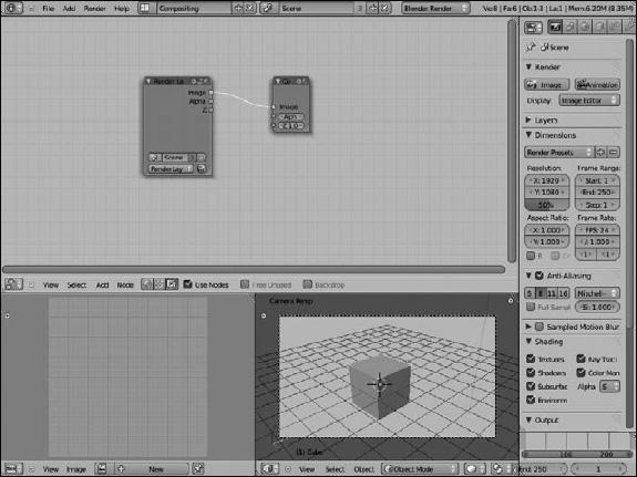
Blender starts by presenting you with two nodes, one input and one output. You can quickly tell which is which by looking at the location of the connection points on each node. The left node labeled Render Layers has connection points on the right side of it. The location of these connection points means that it can serve only as an input to other nodes and can't receive any additional data, so it's an input node. It adds information to the node network. In contrast, the node on the right, labeled Composite, is an output node because it has no connection points on its right edge, meaning it can't feed information to other nodes. Essentially, it's the end of the line, the result. In fact, when you render by using the Node Compositor, the Composite node is the final output that gets displayed when Blender renders.
Setting up a backdrop
I personally prefer to see the progress of my node network as I'm working, without having to constantly refer back to another editor for the results of my work. Fortunately, Blender can facilitate this workflow with another sort of output node: the Viewer node.
To add a new node, position your mouse cursor in the Node Editor and press Shift+A. You see a variety of options. For now, navigate to Output![]() Viewer to create a new output node labeled Viewer.
Viewer to create a new output node labeled Viewer.
If the Render Layer input node was selected when you added the Viewer node, Blender automatically creates a connection, also called a noodle, between the two nodes. Noodles are drawn between the circular connection points, or sockets, on each node. If the noodle wasn't created for you, you can add it by left-clicking the yellow Image socket on the Render Layer node and dragging your mouse cursor to the corresponding yellow socket on the Viewer node.
However, making this connection doesn't seem to do much. You need to take three more steps:
- Left-click the Backdrop check box in the Node Editor's header.
A black box loads in the background of the compositor. (Don't worry; it's supposed to happen, I promise.)
- Go to the Post Processing panel in Render Properties and ensure that the Compositing check box is enabled.
- Render the scene by left-clicking the Image button in the Render panel or pressing F12.
When the render is complete and you return to the Blender interface by pressing F11, the empty black box has been magically replaced with the results of your render. Now anything that feeds into this Viewer node is instantly displayed in the background of the compositor.
This setup is the way I typically like to work when compositing. In fact, I often take it one step farther and press Shift+spacebar to maximize the Node Editor to the full window size. This way, you can take full advantage of your entire screen while compositing.
If you find that the backdrop gets in your way, you can disable it by left-clicking the Backdrop check box in the Node Editor's header, or you can move it around in the compositor by Alt+middle-clicking in the editor and dragging the image around. Also, you can get more space by middle-clicking in the compositor and dragging the entire node network around, or by using your scroll wheel to zoom in and out on the nodes. As of the Blender 2.5 series, you also have the ability to scale the backdrop image by using the V (zoom out) and Alt+V (zoom in) hotkeys. Table 15-3 shows most of the frequently used mouse actions in the Node Editor.
Table 15-3 Commonly Used Mouse Actions in the Node Editor
| Mouse Action | Description |
| Right-click | Select a node. |
| Shift+right-click | Select multiple nodes. |
| Middle-click | Pan compositor work area. |
| Alt+middle-click | Move backdrop image. |
| Ctrl+middle-click | Zoom compositor work area. |
| Scroll wheel | Zoom compositor work area. |
| Left-click (on a node) | Select a node. Click and drag to move the node around. |
| Left-click (on a socket) | Attach or detach a noodle to/from the socket you click on. Click and drag to the socket you want to connect to. |
| Left-click+drag the bottom right corner of a node | Resize the node. |
| Left-click+drag in the compositor workspace | Create a box. Any noodles in the box's area are deleted, leaving just nodes. Think of it as cutting noodles. |
| Ctrl+left-click+drag in the compositor workspace Shift+Ctrl+left-click a node |
Lasso select. Connect the active Viewer node to the output of the clicked node. Continuous Shift+Ctrl+left-clicks iterate through the multiple outputs of the node. |
Identifying parts of a node
At the top of each node are four icons: the triangle on the left and the Plus (+), “equal,” and sphere icons on the right. Following is a description of what each button (shown in Figure 15-9) does:
- Triangle: Expands and collapses the node, essentially hiding the information in it from view.
- Plus (+): Hides and shows sockets that have no connections. This button is useful for simplifying the display of your node network. However, a word of warning: You can easily forget that you have hidden sockets on your node and go a little crazy wondering where they ran off to.
- Equal: This button really isn't an equal symbol. If you zoom in closely, the icon is revealed to be a small slider and value widgets from Blender's interface. If you left-click this button, you toggle the visibility of editable values in the selected node. Any values that you set manually are hidden from view.
- Sphere: View window expand/collapse. This icon is available only on nodes that have an image window, such as a render layer node, any output node, or texture node.
Figure 15-9: Each node has icons at the top that control how you see it in the compositor.

Navigating the node compositor
For the most part, editing nodes in Blender conforms to the same user interface behavior that's in the rest of the program. You select nodes by right-clicking, you can grab and move nodes by pressing G, and you can border select multiple nodes by pressing B. Of course, a few differences pertain specifically to the Node Editor. Table 15-4 shows the most common hotkeys used in Node Editor.
Table 15-4 Commonly Used Hotkeys in the Node Editor

When connecting nodes, pay attention to the colors of the sockets. The sockets on each node come in one of three different colors, and each one has a specific meaning for the type of information that is either sent or expected from the node. The colors and their meanings are as follows:
- Yellow: Color information. Specifically, this socket relates to color in the output image, across the entire red/green/blue/alpha (RGBA) scale. Color information is the primary type of data that should go to output nodes.
- Gray: Numeric values. Whereas the yellow sockets technically get four values for each pixel in the image — one for each red, green, blue, and alpha — this socket gets or receives a single value for each pixel. You can visualize these values as a grayscale image. These sockets are used mostly for masks. For example, the level of transparency in an image, or its alpha channel, can be represented by a grayscale image, with white for opaque and black for transparent (and gray for semitransparent).
- Blue: Geometry data. These sockets are pretty special. They send and receive information that pertains to the 3D data in the scene, such as speed, UV coordinates, and normals. Visualizing these values in a two-dimensional image is pretty difficult; it usually ends up looking like something seen through the eyes of the alien in Predator.
Grouping nodes together
As Table 15-4 shows, you can also group nodes together. The ability to make a group of nodes is actually one of the really powerful features of the Node Editor. You can border select a complex section of your node network and press Ctrl+G to quickly make a group out of it. Grouping nodes has a few really nice benefits. First of all, grouping can simplify the look of your node network so that it's not a huge mess of noodles (spaghetti!). More than simplification, though, node groups are a great organizational tool. Because you can name groups like any other node, you can group sections of your network that serve a specific purpose. For example, you can have a blurry background group and a color-corrected character group.
But wait, there's more! (Do I sound like a car salesman yet?) When you create a group, it's added automatically to the Group menu when you go to add a new node (Shift+A![]() Group). To understand the benefit of being able to add groups, imagine that you created a really cool network that gives foreground elements a totally sweet glow effect. If you make a group out of that network, you can now instantly apply that glow to other parts of your scene or scenes in other .blend files. Go ahead: Try it and tell me that's not cool — you can't do it!
Group). To understand the benefit of being able to add groups, imagine that you created a really cool network that gives foreground elements a totally sweet glow effect. If you make a group out of that network, you can now instantly apply that glow to other parts of your scene or scenes in other .blend files. Go ahead: Try it and tell me that's not cool — you can't do it!
![]() When working with nodes, it's a good idea to have the network flow from the left to the right. Wherever possible, you want to avoid creating situations where you feed a node's output back to one of the nodes that gives it input. This feedback loop is called a cyclic connection. If you've ever heard the painfully loud feedback noise that happens when you place a microphone too close to a speaker, you have an idea of why a cyclic connection is a bad idea.
When working with nodes, it's a good idea to have the network flow from the left to the right. Wherever possible, you want to avoid creating situations where you feed a node's output back to one of the nodes that gives it input. This feedback loop is called a cyclic connection. If you've ever heard the painfully loud feedback noise that happens when you place a microphone too close to a speaker, you have an idea of why a cyclic connection is a bad idea.
Discovering the nodes available to you
Blender has quite an extensive list of nodes that you can add to your network. In fact, it seems like with every release of Blender, more and more incredible node types are added to the compositor. Many nodes have a Fac, or factor, value that you can usually either set with a value from another node or explicitly set by typing. Values less than 1 make the node have less influence, while values greater than 1 make the node have more influence than usual over the image.
Input
The input nodes are one of the two most important node types in the Node Compositor. If your node network doesn't have any inputs, you don't have a composite. Figure 15-10 shows each of these nodes side by side.
Figure 15-10: Input nodes: Render Layer, Image, Texture, Value, RGB, and Time.

- Render Layer: This node feeds input from a scene into the compositor. The drop-down menu at the bottom of the node allows you to pick any of the render layers you created in any scene. Notice also the button with the camera icon that is to the right of this menu. Left-click this button to render just this layer. This handy feature allows you to update a portion of your node network without needing to rerender all the layers in the network.
- Image: The name for this node is a bit oversimplistic because it can actually load more than just a single still image. The Image node allows you to bring any sort of image data into the compositor, including sequences of images and movie files, and allows you to control when the sequence starts, how long it is, and whether to loop it continuously.
- Texture: The Texture node is unique as an input node in that it's the only one that can actually receive input data as well. Through this node, you can take any texture that you built in Blender and add it to your node network. This node is particularly useful with UV data because it can actually let you change the textures on objects in your image without rerendering.
- Value: This fairly simple input node allows you to feed any scalar (numerical) value to other nodes.
- RGB: With the RGB node, you can feed any solid color to any other node in the compositor. This node is a good, quick way to adjust the hue of an image or provide a simple colored background.
- Time: This node is probably one of the most powerful, yet misunderstood, nodes in Blender. In the past, the Node Compositor was not tied to the Graph Editor, making it difficult to animate attributes of individual nodes. The Time node was a way around this obstacle. Fortunately, as of Blender 2.5 and the ability to animate nearly everything, the Time node is less of an absolute necessity in the compositor. You can key node values just like any other value in Blender. However, the Time node is still useful.
Output
Input nodes are one of the two most important node types in Blender. As you may have guessed, the Output nodes are the other important node types, for a similar reason. If you don't have an output node, Blender doesn't know what to save when it renders. The following are the two most-used Output nodes:
- Composite: Blender recognizes the Composite node as the final output from the Node Compositor. When you set up your output files for animation in Render Properties, or when you press F3 to save a render, it's the information from this node that Blender saves out.
- Viewer: The Viewer node is similar to the Composite node, but it's not necessarily for final output. Viewer nodes are great for spot-checking sections of your node network and making sure that things are going the way you want them to. Also, output from these nodes is seen in the compositor's backdrop, if you enable it.
Color
The Color nodes have an enormous influence over the look of the final output. These nodes directly affect how colors appear, mix, and balance in an image. And because an image is basically just a bunch of colors arranged in a specific pattern, you can understand why these nodes have so much control. Figure 15-11 shows some of the most commonly used Color nodes. Following are descriptions of each node type:
Figure 15-11: Color nodes: RGB Curves, Mix, AlphaOver, and Z Combine.

- RGB Curves: Arguably one of the most powerful color nodes, the RGB Curves node takes image data and allows you to use curves to adjust the combined color, or any of the red, green, or blue channels in the image individually. Left-clicking the C, R, G, and B buttons on the upper left changes between combined, red, green, and blue color channels, respectively. With this node, you can do anything that the Hue Saturation Value, Bright/Contrast, and Invert nodes can do, but with more control.
- Mix: I personally use this node quite a bit. The Mix node has 16 different blending modes to allow you to control how to combine two input images. If you've used image editing software like GIMP or Photoshop, these blending modes should be pretty familiar to you. One thing to remember in this node — and it's something I used to constantly get backwards — is that the upper image input socket is the background image, whereas the lower image input socket is the foreground image.
- AlphaOver: This node is very similar to the Mix node, except it deals exclusively with combining images using their alpha channels. The lower socket is the foreground, and the upper socket is the background image. The other thing to note with this node is the Convert Premul check box. Basically, if you see weird white or black edges around parts of your foreground elements, left-clicking this button usually fixes them.
- Z Combine: Like the Mix and AlphaOver nodes, the Z Combine node mixes two sets of image data together. However, instead of using color information or alpha channels, this node can use Z-depth information.
Vector
Vector nodes use 3D data from your scene to influence the look of your final 2D image. The usage of these nodes tends to be a bit advanced, but they allow you to do things like change the lighting in a scene or even change the speed that objects move through the scene . . . all without rerendering! If you render to an image format that understands render passes, like the very cool OpenEXR format (more on this topic in the next section), and you include vector and normal passes, these nodes can be a huge timesaver.
Filter
Filter nodes can drastically change the look of an image and are probably the No. 1 way to fake any effect in an image. These nodes actually process the pixels in an image and can do things like put thick black lines around an object, give the image a variety of customized blurs, or make bright parts of the image glow. Figure 15-12 shows some of the most useful Filter nodes:
Figure 15-12: Blur, Vector Blur, Defocus, and Glare nodes.

- Blur: As its name implies, this node applies a uniform blur across the entire input image. The first button gives you a drop-down menu to select the type of blur you want to use. I typically like to use Gauss for most of my effects. When you first apply this node, you may not think that anything is happening. Change the values in the X and Y buttons to adjust the blur size on a scale from 0 to 256, or 0.0 to 1.0, depending on whether you enable the Relative check box.
- Vector Blur: This node is the fastest way to get motion blur out of Blender. The Vector Blur node takes speed information from the Vector pass (enable Vector in the Layers panel of Render Properties) and uses it to fake the motion blur effect. One check box I recommend you enable in this node, especially if you're doing character animation, is the Curved check box. This option gives objects that are moving in an arc a more natural, curved motion blur. This node is specifically for use with 3D data coming from Blender. It can't add motion blur to just any footage.
- Defocus: Blender's Defocus node is the way to fake the depth of field, or DOF, effect you get with a real camera. If you've seen a photo where something in the middle of the picture is in focus, but objects in the foreground and background are blurry, it's called a shallow DOF, and it looks pretty sweet. You can get an idea where the camera's focal point is by selecting the camera in your scene and turning on Limits for the camera in its Object Data Properties. Then when you adjust the DOF Dist value, you can see the focal point as a yellow cross.
- Glare: This node is a really quick way to give the bright parts in your render just a little extra bit of kick. The Fog Glow and Streaks options in the first drop-down menu are what I tend to use the most. Of all the values, this node gives you to play with, probably the most influential one is Threshold. Setting the threshold to values between 0.0 and 1.0 tends to work best for me, but results vary from one image to the next.
Converter
These handy little utility nodes have a variety of purposes, including converting one set of data to another and ripping apart or recombining elements from a rendered image. The Color Ramp and ID Mask nodes in particular get used quite a bit. The Color Ramp node is great for helping visualizing or revisualizing numerical values on a scale. For example, the only way to get a good sense of what the Z-depth of an image looks like is to map Z values along a manageable scale and then feed that to a white-to-black color ramp, as shown in Figure 15-13.
The ID Mask node is handy because it allows you to isolate an object even more specifically than with layers and render layers. Assume that you want to apply the Glare node to a ball that your character is holding. If the scene is complex enough, it doesn't really make a lot of sense to give that ball a layer all by itself. So you can give the object a Pass Index value in the Relations panel of Object Properties. Then by using the ID Mask node, you can isolate just that ball and make it all shiny.
Figure 15-13: Visualizing a scene's Z-depth using a ColorRamp.

Matte
The Matte nodes are specifically tailored for using color information from an image as a way of isolating certain parts of it. Matting is referred to as keying because you pick the main color, or key color, to represent transparency. Keying is the fundamental basis for those cool bluescreen or greenscreen effects used in movies. The filmmaker shoots the action over a blue or green screen (blue is used for analog film, whereas green is typically used for digital footage), and a compositor removes the blue or green and replaces it with other footage or something built in 3D.
Distort
The Distort nodes typically do general-purpose image manipulation operations like Translate, Rotate, Scale, Flip, or Crop.
![]() Want to do that spinning newspaper effect you see in old movies? Wire an image of a newspaper and the Time node to the Rotate and Flip nodes, and you've got it! However, three special Distort nodes are worth talking more about: Displace, Map UV, and Lens Distortion. Figure 15-14 shows each of these nodes.
Want to do that spinning newspaper effect you see in old movies? Wire an image of a newspaper and the Time node to the Rotate and Flip nodes, and you've got it! However, three special Distort nodes are worth talking more about: Displace, Map UV, and Lens Distortion. Figure 15-14 shows each of these nodes.
Figure 15-14: Distort nodes: Displace, Map UV, and Lens Distortion.
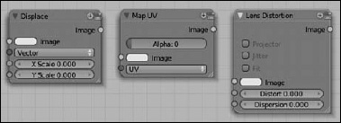
- Displace: This node is great for doing quick-and-dirty image distortions, such as generating heat waves in the desert, faking refraction, or making an object appear to push through the image on the screen. The key is the Vector input socket. If you feed a grayscale image to this socket, it uses those values to shift pixels in the image. Connecting a color image, normals, or vectors shifts the image around with a more three-dimensional effect, thereby giving you things like the heat wave effect.
- Map UV: In this entire chapter, I talk about how one cool thing that the Node Compositor can do is change textures on objects after you've already rendered them. Well, the Map UV node gets you that awesome functionality. To use this node, you need to enable the UV pass on your render layer. Feed that pass to this node, along with the new texture you want to use, and BAM! Your new texture is ready to be mixed back with the image. To make sure that you're changing the texture on the right object, combine the Map UV node with the ID Mask node before mixing.
- Lens Distortion: Sometimes you want to introduce the effects that some special (or, in some cases, poor) lenses have on the final image. The Lens Distortion node produces those effects for you. You can get everything from a wide fisheye lens look to that strange effect when an old projector isn't calibrated properly and the colors are misaligned.
Group
When you press Ctrl+G to create a node group, that group is placed in this menu. When you group a set of nodes, you instantly have the ability to apply that network to other parts of your composition. Also, grouping gives you the ability to share node networks between .blend files. When you append or link a node group from another file, it shows up in this menu. There's more on grouping in this chapter in the section “Grouping nodes together.”
 Whenever you have the opportunity, name everything you create. Unique names are especially important for groups because they're automatically added to the Group menu. Using names that make sense makes choosing the right node group a lot easier. You can always rename node groups from the Properties region of the Node Editor (N).
Rendering from the Node Compositor
If you're using the Node Compositor, you already know all the basic steps for getting a rendered image out of it. Of course, if you skipped straight to this section, here's the quick version: Make sure that the Compositing check box in the Post Processing panel of Render Properties is enabled.
That said, you need to know one other thing about rendering from the Compositor. Say that you're working on a larger production and want to save your render passes to an external file format so that either you or another compositor can work on it later without rerendering the whole scene. You'd have to save your renders to a file format that understands render layers and render passes. That format is the venerable OpenEXR file format, developed and gifted to the world by the cool people at Industrial Light & Magic.
Now I know what you're thinking, “Using this format is as easy as setting up my render layers and then choosing OpenEXR from the menu in the Output panel of Render Properties.” You're actually two-thirds correct. You do set up your render layers and you do go to the Output panel. However, choosing OpenEXR saves only the final composite output (not the layers or passes) in an OpenEXR file (extension .exr). In order to get layers and passes, you should instead choose MultiLayer. With this format, you get an OpenEXR file that has all the layer and pass information stored with it.
 Pay close attention to your hard drive space when you choose to render to OpenEXR with all your layers and passes embedded. Keeping all your render layers and passes is a great way to tweak and make adjustments after rendering. However, the file size for each individual .exr file can be huge. Whereas an HD frame in PNG format may be only a couple hundred kilobytes, an OpenEXR file on the same single frame with all the passes enabled may be well over 100 megabytes — yes, megabytes. And if your animation has a length in minutes, that 100 megabytes per frame starts taking up space quickly. So make sure that you do test saves to get a good benchmark for the file size and see that you have enough hard drive space to store all those frames.