
CHAPTER 13

Secondary Motion and Breaking Joints
Chris Tedin
Rule: Secondary motion and overlapping motion
After Completing This Chapter, You Will be Able To:
• Animate limbs with sequential breaking joints.
• Create cloth simulations with realistic effects.
• Create hair simulations using cloth system.
• Use spring controllers to simulate body jiggle.
Creating natural, believable movement is one of the most challenging jobs in the industry. Humans move with an amazing level of complexity and with an almost infinite variety. Factors such as age, gender, size, physical build, emotion, and physical language all play a part in each individual’s movement and timing. Understanding takes a great deal of observation. Professional animators watch people as they move for hours at a time, often videotaping where appropriate, such as public places. Old men getting up from a picnic bench, feeling the weight of their bones, aches and pains from an injury long ago, can be a great inspiration for a short film. In contrast, a room full of 6-year-old children happily playing hide and seek could fuel the creativity of any ambitious animator. Anyone or anything can be a great subject for animation, as long as the artist approaches them with loving care and attention.
Tail Wag
This chapter will look at a group of animation techniques that are lumped into a large group: “secondary motion.” In the broadest sense, secondary motion is any movement that comes after the motion that is initially directed by the character, animal, machine, or object. For example, when a fat character jumps up and down, the belly will tend to wiggle after the primary motion has finished. When a walking woman wearing a long dress suddenly stops, the gown might flow around her for a few seconds before coming to a rest. We will also talk about the concept of “breaking joints,” which can be seen in a wagging tail. The base of the tail might move first, while the tip follows behind a fraction of a second, like the action of a whip. Fish and whales demonstrate this motion effectively while gliding and darting through the water. Even humans, such as a ballet dancer, gracefully extend their shoulders, arms, wrists, and fingers in a beautiful flowing sequence, avoiding the abrupt sudden stop of the entire arm. In fact, this “breaking” is common in almost any human movement and is something to keep watch for while observing your subjects.
1. We will begin by creating this “breaking joint” movement using a simple wagging tail. Open the “Tail_Wag.max” file to work along with this section. Maximize the top viewport and double click the first bone in the viewport. This selects all the bones in the rig.
2. Next, click the Curve Editor button on the Main toolbar. When the editor opens, click “Modes” on the Menu Panel and change it to Dope Sheet. The bones are listed on the panel on the left, indented to indicate their parent-child relationship.
Notice how all the keys in the rig are lined up on every 10th frame.

FIG 13.1
3. Double click Bone002, which is the second bone in the hierarchy. Notice that the first bone disappears, and only Bone002, Bone003, Bone004, and Bone005 remain in the Dope Sheet Editor. The Editor’s filter has been set to show only selected and animated objects. All other objects disappear. This is to keep things simple for the animator, but those settings can be changed if you wish.
4. Move all the remaining keys on the Editor 2 frames to the right. This will delay their motion slightly. Notice how the keys on the bottom panel under the Time Slider also move slightly. This compact view of the Dope Sheet shows all keys for the selected objects but compresses them onto a single timeline. It is best to use the full Dope Sheet until you get more experience and use the compact viewer for animating single objects.
5. Next, double click Bone003 and move their keys a few frames to the right. Repeat this for the remaining bone, Bone004. You can ignore the last bone, which is the tip, and is not animated.
6. Now, close the Dope Sheet and play the animation. You can see how the motion is much more fluid and “soft”. Open “Tail_Wag_Finished.max” to see the final result. You can also use this technique to simulate a more fluid whipping motion or fish-like motion by simply moving each set of keys a bit more (perhaps 3 frames), and the effect is much more extreme. Open “Tail_Wag_Fish.max” to see this result. Notice that by simply moving a key can have a big effect on the final look of the animation. Of course, if you want a more spring-like effect, more like a whippet than a golden retriever, you could delay the keys a single frame. The choice is yours.
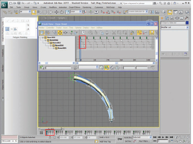
FIG 13.2
This is a simple technique, and the effect is easily achieved. Take this to another, more nuanced example, and you can see how this technique still works very effectively.
7. Open “Secondary_Fishing_Pole_Start.Max”, an arm casting a fishing pole. Scrub the timeline a bit, or play in real time and you will see a fairly typical “pose to pose” motion. The entire motion is contained within 5 keys, spaced out in gradually increasing speed.

FIG 13.3
Not bad for a first round of animation, but the motion in the arm is rather stiff. Notice that we’ve added a little “overshoot” to the arm motion. This is where the arm moves a little past the final key and bounces back to its final resting pose. We will use the same technique as the tail to add some flexibility and naturalism.
8. Double click the elbow. Select all the keys in the timeline below the viewport. If you wish, open up the Dope Sheet to manipulate the keys instead. Slide the keys over 3 frames to the right.
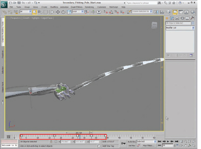
FIG 13.4
9. Next, double click the palm of the hand to select all the bones in the fishing pole as well. Slide these keys over 4 frames. Play the animation and notice how much more natural the motion has become.

FIG 13.5
To create more of a whip-like motion, you could delay the bones slightly along the length of the pole. This creates a much softer effect, more appropriate for a riding whip or a softer bamboo fly-fishing pole. Double click BoneWhip01 and move the keys over 1 frame. Next, double click BoneWhip04 and move 1 frame, then BoneWhip07 and move 1 frame. Selecting every third frame makes the motion much more subtle. Delaying each and every bone sequentially would create an action that is much too slow and unrealistic, but might be perfect for delaying a large bullwhip.
Open the Layer Manager and unhide the Mesh layer. Hide the bone layer and play the animation to see the final result. If you look at the Dope Sheet, you notice I moved all the keys for the fly rod back 3 frames while keeping the delay along the length, just to give it a bit of snap. I realized that it started to flex a bit before the arm moved down to its full resting position, more like a spring. Double check the timing on all of your motions to be sure it looks correct. There are seldom any hard and fast rules about these motions, and different materials will act in completely different ways. Close observation is always important, and do some tests to compare their motion. Use the Tools>Grab Viewport>Create Animated Sequence File to play these animations in real time. Use the “Rename Sequence File” to save different tests for comparison.
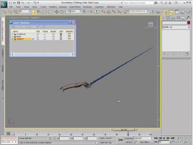
FIG 13.6
Cloth
Animating realistic clothing has been the challenge for film studios for many years. In the early days of computer animation, clothing was hand animated using bone systems and deformers. In the last decade, there have been a number of simulation systems created specifically to handle the challenges of cloth. 3ds MAX has a very robust and flexible system to deal with cloth. We will use it for the next exercise.
Open the file named “Secondary_Cloth_Skirt_Start.max”. Here you will see a rather abstracted young woman going through a few fanciful dance moves. She is built with few polygons so that the simulation will run a bit quicker.
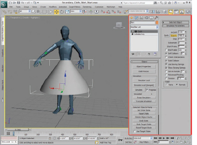
FIG 13.7
The skirt has a moderate number of polygons. The more polygons that a piece of clothing has, the longer it will take to run the simulation. However, the results won’t be acceptably realistic unless there are enough to describe the folds and creases. It depends on the situation, and you can add polygons in areas that you know will have more folds, such as elbows, armpits, and the inseam of pants. We will run this simulation with a fairly low poly count but feel free to add more polygons to this mesh and run it again for better results.
1. Click on the skirt object and add a Cloth Modifier to it. This is a pretty complex modifier, with a great deal of parameters you can adjust, so you might want to pull the Modifier Panel out to see all the settings. Click on “Object Properties” and you will see the main Cloth Simulation Panel. Select the “Skirt” object in the object list. Click the Cloth setting and select the Cloth Properties Preset rollout, and select “Satin.”
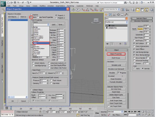
FIG 13.8
Next, and equally important, add the woman’s mesh to the simulation. On the upper left corner click “Add Objects”… and add “Figure” to the simulation. It’s important to understand that every object in the cloth simulation is actually part of a single modifier. All elements you want to add to the simulation should be added using this panel, rather than adding a new modifier.
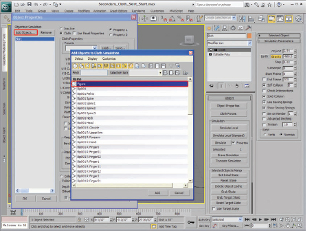
FIG 13.9
2. Once the “Figure” mesh has been added, click “Collision Object” to make this mesh a collision mesh. Set the offset to 0.7. This is the distance that the skirt will be kept away from the body mesh. Too far, however, and it will be pushed away from the waist far too much.
3. Now, turn on the Sub-Object mode of the modifier and select “Group.” We need to bind the waist of the skirt to the “Figure” mesh, and we need to make a selection of the mesh into a group. Select the top row of vertices and select “Make Group.” Name this group “Waist.”
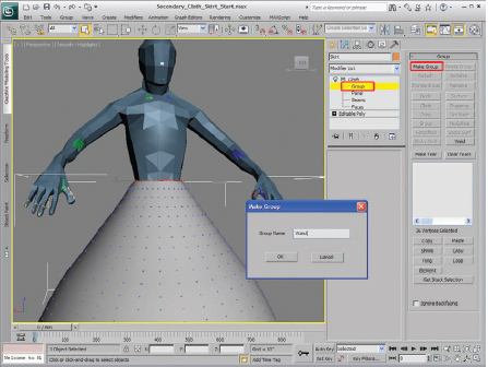
FIG 13.10
4. Now, with this group created, now it needs to be assigned to an object. In this case, it will be the surface of the dancing figure. Click “Surface,” and select the figure’s mesh. The group is now assigned to the figure’s mesh and will now stick to it during the simulation.
5. Much of the realism of cloth is related to the scale of the simulation. Setting the cm/unit to the right amount is important. Too small and the cloth looks like a napkin. Too large, and it acts like a huge tarp. Set this simulation to 3.0 for now. Turn on self-collision and click “Simulate.” Watch as the cloth drapes slowly down to the woman’s body. Stop the simulation after a few frames by clicking “Cancel” or pressing the Esc button on the keyboard. If you click “Simulate” again, the simulation will continue where it left off. Press the Play button and watch the simulation in real time. Feel free to add a TurboSmooth on top of the mesh. It adds a nice smoothing effect to the skirt without adding any calculations to the simulation.

FIG 13.11
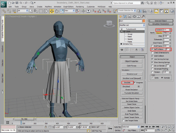
FIG 13.12
6. Now, click “Simulate” again and let the simulation run a bit longer. Watch and see if the leg mesh comes through the skirt. If it does, simply increase the subsamples. Doing so increases the simulation time a great deal, so do this with care. It is normal for the leg mesh to peek out of the cloth mesh from time to time, especially during quick movements. Increasing the Subsample amount and perhaps the Collision Offset may help fix this.
7. As this simulation runs, the simulation data that is created (which stores the movement of the cloth object) is stored in a temporary cache file. You can save this file to your hard drive and apply it to the same mesh later. This allows you to save several simulations and compare them later for the best results.
8. Simply open up the “Selected Object” rollout and click the “Set…” button. A Dialog box appears and allows you to create the cache file. Save this file with a name that best describes the movement. I saved this file as “Skirt_Dance01.cfx”. Next, click “Save” to save the effect to the cache file. Any changes to the effect can now be saved to this cache file with the “Save” button. You can also switch simulation cache files by clicking “Import…” and loading up the new cache file.
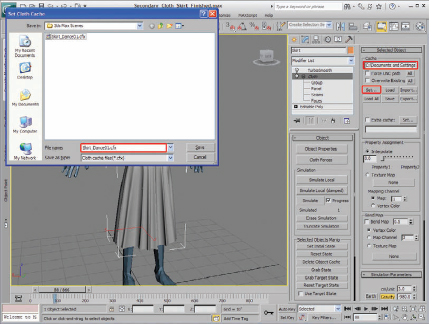
FIG 13.13
Once you have saved this cache file, test the result by clicking “Erase Simulation.” Then, click “Import…” and load the file. The cloth will simulate properly.
9. Now, for some extra flourish, let’s add some wind to the effect. This is very easily done. First, click on the “Space Warps” tab in the Create Panel. Create the wind object and turn it 90°. I have turned mine to the left a bit, but you can turn it any direction you like.

FIG 13.14
10. Then, open up the object’s Cloth Modifier. Click the “Add Forces” button. You should see the wind object in the left panel. Select it and click the right arrow to add it to the simulation. That’s it. Delete the simulation by clicking the “Erase Simulation” button and resimulate it. You should see the effects immediately.
11. If the effect is too much, simply stop the simulation, select the wind object and lower the Strength amount (I set mine to .35), erase the simulation and resimulate. You can also animate the direction of the wind, add turbulence, and change the frequency for even more subtle motion.
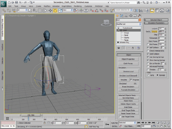
FIG 13.15
Now, let’s add a ponytail to the character. Although we will be using the Hair and Fur system in 3ds MAX, we won’t be using its built-in deformation system for this example. The results are fairly good, but not for something like a ponytail object, which behaves much more like a single cloth mesh, rather than individual strands, which is how the Hair and Fur system generally simulates with its dynamic system.
12. Open the file “Cloth_Hair_Start.max”. This is basically where we left off with the skirt simulation. I have added a few objects, however. There are a series of lines with a Hair and Fur Modifier added. This can be easily done by creating a single line, copying it over a few times. Then, select one of the lines, click the Attach button, and select the other lines one at a time. The order in which you attach the lines is important, because the hairs will be added in between each line in that exact order. I already attached them together and added the Hair and Fur Modifier, but feel free to do this yourself if you wish.
13. Next, add a “Skin Wrap” Modifier to these lines. This modifier is automatically placed below the Hair and Fur Modifier, since Hair and Fur is considered a “World Space Modifier” and is always added last on the modifier stack. Now, the hair will follow the motion of the HairSimulationMesh object.

FIG 13.16
Now, all we need to do is add the “HairSimulationMesh” to the cloth simulation. Since we have already added the skirt object and finished the simulation, we can add a new Cloth Modifier to this object. As long as the hair and skirt aren’t going to be colliding, they can be simulated separately. This will speed up the simulation significantly and prevent the time-consuming resimulation of the skirt object.
14. Add a new Cloth Modifier to the “HairSimulationMesh” object. Just as before, open the Properties for the object, and make it a Cloth object.
15. Add a new object into the scene, select the Figure, and make that a Collision object.
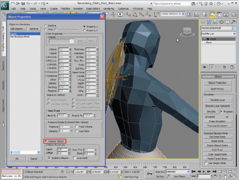
FIG 13.17
16. Next, select “Groups” in the Sub-Object mode of the Cloth Modifier, select the top vertices of the “HairSimulationMesh,” and click the “Make Group” button to make those vertices a group. Name this group “HairRoots.”

FIG 13.18
17. Then, click on “Surface,” then select the “Figure” mesh to assign this group to the “Figure” surface. Get out of Sub-Object mode.
18. Open up the Properties Panel again, and adjust the settings of the Ponytail a bit more. I found these settings to work pretty well for a start. The “cloth” object needs to be a bit stiffer and heavier to act like hair. Finally, open the “Forces” Panel and add the wind force.
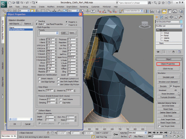
FIG 13.19
19. Run the simulation and check out the final results. You can hide the HairSimulationMesh if you like to see how the hairs move by themselves.
Spring Constraints
Many objects can be effectively simulated with a very simple constraint called a “Spring Constraint.” It simply constrains two objects together, so that if one object is moved, the other object is pulled along as though on the end of a long spring. The Spring Constraint can be adjusted in terms of tension and mass, which creates variations in the motion of the “following” object. One of the best ways to use this kind of constraint is to simulate a large belly.
1. Open the file called “Secondary_Belly_Start.max” and you will see a file very similar to the one we used for the skinning exercise, but this one gained a bit of weight. I have added a few bones to the middle of the belly mass, with the pivot point near the back of the spine so that the belly jiggles in a more vertical direction. I created an IK system for the end of the bone and constrained the goal of the IK to a point object. I have also placed a point object above this bone, which is linked to the lower spine of the biped system.
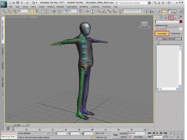
FIG 13.20
The character mesh’s skin includes two additional bones and is weighted so that when they move, the belly will move with them. Scrub the Time Slider a bit and you will notice that the end of the bone has not been linked to the biped, so it doesn’t move in space. We will change that next.
2. Select the green point object that is on the end of the bone. Be careful not to select the cross-shaped goal object of the IK system, which is blue. Open up the Motion Control tab on the Command Panel. Click the Parameters button, select the “Position” controller, then “Assign Controller”, and finally select “Spring” as the controller type.
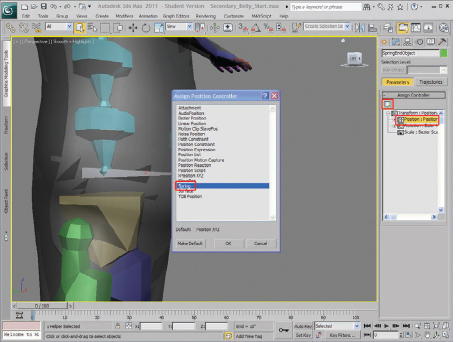
FIG 13.21
3. Once this is selected, the Spring Controller Property Panel appears. Click the “Add” button and select the top point object. There should now be two objects in the list below. Each object has its own influence over the motion of other object.
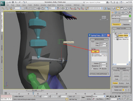
FIG 13.22
4. Currently, the object itself, called “Self Influence,” has as much control as the top object. Let’s change this. Select the “Self Influence,” and make the “Tension” amount 0.00. Next, select the “SpringStartObject” and set the Tension to 1, the Dampening to 0.5, the Mass to 500, and the Drag to 0.6. Play the animation again and notice the change in the movement of the belly mass. If you change these numbers around, you can change the behavior of the belly. Generally, if you decrease the Mass, increase the Tension, and decrease the Dampening, the jiggling will appear faster and less massive.

FIG 13.23
The Spring Controller is one of the most useful controllers for creating believable simulations. It can be used for a wide variety of applications. Any situation that calls for a swinging motion can use this controller. Imagine a large walking mech vehicle, with hoses and dangling weaponry, each part moving individually with its own weight and timing. This can create a very convincing effect if used carefully.
Now, let’s combine the Spring Controller and the “Tail Wag” demo and create a more elaborate system. The advantage to this tail system is that it is completely adjustable by the animator. The animator can keyframe the rotation of each of the bones in this system, and the computer will add the secondary wag on top of this primary movement.
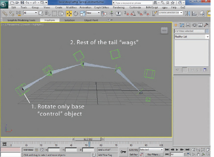
FIG 13.24
Open the file “SecondaryTailRig_SpringConstraints.max” to see the final file. Rotate the base point object and set animation keys, and then play back the animation to see the final results. The Spring Controller delays the animation cycle through each of the point objects (the smaller ones, which contain the Spring Controller) each offsetting the delay, creating a whip-like motion.
1. Begin by drawing five bones in the viewport. Use the front viewport so that they align properly. Use Create>Systems>Bones on the right panel.
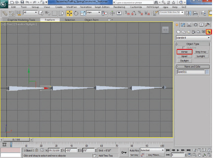
FIG 13.25
2. Next, select the base of each bone, click on the menu Animation>IK Solvers>HI Solver. With this tool now active, click the base of the first bone. A dotted line will appear. Next, click on the base of the second bone.
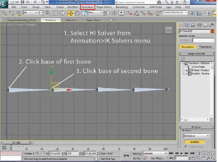
FIG 13.26
3. Repeat this process for the rest of the bones. You should have an IK system at the base of each bone, each extending to the base of the next bone in the chain.

FIG 13.27
4. Next, create a point object and use the Align Tool to align it to the IK Goal of the first IK object.
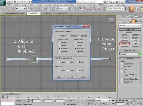
FIG 13.28
5. Repeat this process for the rest of the bones. You should have point objects at the location of each IK Goal.
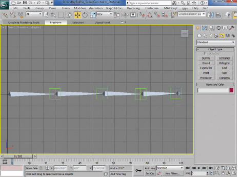
FIG 13.29
6. Link each IK Goal to the nearby point object. Use the Link Tool in the upper left command panel.
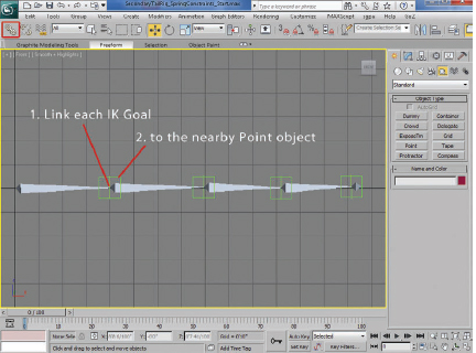
FIG 13.30
7. Next, create a new set of point objects; these are a little larger, at each location, with an extra one at the base of the first bone. Use the Align Tool to align them to the smaller point objects. Feel free to color-code these objects with a slightly different color to avoid confusion.
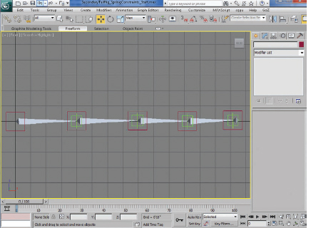
FIG 13.31
8. Now, we will use the Spring Controller to delay the motion of the little point objects relative to the larger ones. Click each of the smaller point objects (be careful not to select the IK Goals by mistake. It would be a good idea to hide these by using the Display Panel and selecting IK Objects in the lower selection set. The goal objects will disappear, but you won’t need to select them anyway.)
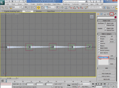
FIG 13.32
9. Select the small point object at the end of the first bone.
(a) Open up the Motion Control Panel.
(b) Select “Position: Position XYZ” controller.
(c) Click “Assign Controller” button above.
(d) Click “Spring,” and then click OK.
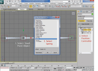
FIG 13.33
10. The Spring Parameters window will now appear, and you can adjust the values for the Spring Controller. For now, increase the drag to 2.

FIG 13.34
11. You can always open this parameter panel by double clicking the Spring Controller in the “Assign Controller” Outline Panel, or by clicking “Spring” in the “Position List” and adjusting the parameters in the “Spring Dynamics” tab below.

FIG 13.35
12. Now, link each of the large point objects together into a hierarchy. Use this diagram to show the linking order. This is very important to get right, or the system doesn’t work properly.
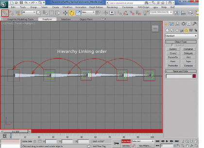
FIG 13.36
13. Now, set a few rotation keys for the base point object and watch the tail wag!
14. If you wish, you can pose the tail before simulation. Simply move the large point objects into the pose positions and run the simulation again. The simulation will work for those new positions. You can also animate the position of the large point objects, and the simulation will be added to that animation.

FIG 13.37
Some animators prefer having complete control over every aspect of a character or object’s motion during an animated sequence. However, as scenes become more complex and more software sophisticated, many large animation and visual effects companies have set up entire departments to handle simulations and secondary motion. Many large visual effects studios are even developing their own simulation software. Many of the simulation systems operate in a very similar way to the techniques we have demonstrated here.