
03
Job:02-30056 Title: RP-Interior Design Reference and Specification
#175 Dtp:216 Page:44
(RAY)
024-057_30056.indd 44 3/4/13 7:22 PM
4 4
THE INTERIOR DESIGN REFERENCE + SPECIFICATION BOOK
Text
THREE-DIMENSIONAL DRAWING TYPES
Three-dimensional drawings are used in interior projects to demonstrate aspects of the design
that cannot be readily understood through two-dimensional representations. In general, three-
dimensional drawings should clarify the intent of the design. In interiors, they can demon-
strate and explain many aspects of a project: furniture details, color, nish, light, and shadow.
Numerous types of three-dimensional drawings can be incorporated into a project, including
paraline drawings—where all lines in the image remain parallel to each other—and perspec-
tive drawings—where lines converge to points on a horizon.
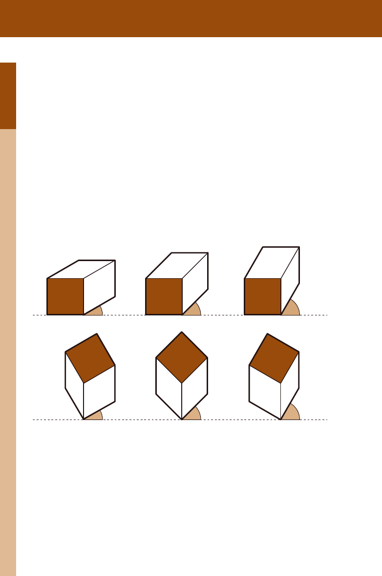
Paraline Drawings
Also known as axonometric, isometric, and oblique, paraline drawings are extremely useful
to the designer as they represent the third dimension in ways that are parallel and measur-
able, and combine plan, section, and elevation into a single drawing. The choice of angle will
emphasize certain parts of the object; choosing the correct angle and projection method is
essential to the success of the drawing as a communicative tool.
Elevation Obliques
Plan Obliques
30˚ 45˚ 60˚
30˚ 45˚ 60˚
Isometric and Dimetric
Trimetric
Oblique Projections
Oblique projections can be either plan- or elevation-based. Plan obliques allow for a true plan
to be used in the construction of the drawing. The angle of view is also higher than in other
projections. Elevation obliques draw a true elevation in the picture. For both, an angle is
chosen to represent the volume of the object (usually 30 or 45 degrees), and the depth of the
object is extruded from the picture plane. Oblique drawings often appear distorted and are
compressed by a third or a half to restore proportion to the object.
Isometric, Dimetric, and Trimetric Projections
Isometric, dimetric, and trimetric projections constitute the second classication of paraline
drawings, and all are referred to as axonometric drawings. In these, the angles from which the
object is viewed is lower than in obliques. Often, plans and sections cannot be used as the
basis of the drawing, as there is inherent distortion in each projection. In an isometric projec-
tion, the three axes of the object are equal in angle to the picture plane and are foreshortened
equally. Because of this equality, isometric projection is the most popular of the axonomet-
ric types. A dimetric projection foreshortens two axes and the third is either elongated or
shortened to prevent distortion. In a trimetric drawing, all axes are foreshortened by different
amounts.
On occasion, designers may prefer the exploded axonometric, a technique of pulling individual
faces away from the object to reveal elements within. Key to the exploded axonometric draw-
ing is the ability for the eye to reconstitute the complete object. Dashed lines are added to
this drawing to indicate the direction and length to which the drawing has been taken apart.
Job:02-30056 Title: RP-Interior Design Reference and Specification
#175 Dtp:216 Page:44
(RAY)
024-057_30056.indd 44 3/4/13 7:23 PM

03
Job:02-30056 Title: RP-Interior Design Reference and Specification
#175 Dtp:216 Page:45
Job:02-30056 Title: RP-Interior Design Reference and Specification
#175 Dtp:216 Page:44
(RAY)
024-057_30056.indd 45 3/4/13 7:22 PM
45
Drawing Basics
Text
Three-dimensional drawings are used in interior projects to demonstrate aspects of the design
that cannot be readily understood through two-dimensional representations. In general, three-
strate and explain many aspects of a project: furniture details, color, nish, light, and shadow.
able, and combine plan, section, and elevation into a single drawing. The choice of angle will
Isometric and Dimetric
Trimetric Exploded Axonometric
Oblique projections can be either plan- or elevation-based. Plan obliques allow for a true plan
degrees), and the depth of the
Isometric, Dimetric, and Trimetric Projections
Isometric, dimetric, and trimetric projections constitute the second classication of paraline
drawings, and all are referred to as axonometric drawings. In these, the angles from which the
object is viewed is lower than in obliques. Often, plans and sections cannot be used as the
basis of the drawing, as there is inherent distortion in each projection. In an isometric projec-
tion, the three axes of the object are equal in angle to the picture plane and are foreshortened
equally. Because of this equality, isometric projection is the most popular of the axonomet-
ric types. A dimetric projection foreshortens two axes and the third is either elongated or
shortened to prevent distortion. In a trimetric drawing, all axes are foreshortened by different
amounts.
On occasion, designers may prefer the exploded axonometric, a technique of pulling individual
faces away from the object to reveal elements within. Key to the exploded axonometric draw-
ing is the ability for the eye to reconstitute the complete object. Dashed lines are added to
this drawing to indicate the direction and length to which the drawing has been taken apart.
Job:02-30056 Title: RP-Interior Design Reference and Specification
#175 Dtp:216 Page:45
Job:02-30056 Title: RP-Interior Design Reference and Specification
#175 Dtp:216 Page:44
(RAY)
024-057_30056.indd 45 3/4/13 7:23 PM

03
Job:02-30056 Title: RP-Interior Design Reference and Specification
#175 Dtp:216 Page:46
(RAY)
024-057_30056.indd 46 3/4/13 7:22 PM
4 6
THE INTERIOR DESIGN REFERENCE + SPECIFICATION BOOK
Text
Perspective Drawings
Interior perspective drawings do not differ in construction from their architectural counter-
parts, though their obvious focus on the interior makes the choice of reference point much
easier. Care must be taken, however, not to distort the image by making the cone of vision
too large an angle or the picture frame too wide.
HL
GL
elevation
with ML
HL
GL
SP
elevation
with ML
PP
PP
Picture Plane (PP): Flat surface, always
perpendicular to the viewer’s center of vi-
sion, on which the image in perspective is
projected.
Station Point, or eye point (SP): Locates
the position and height of the viewer.
Horizon Line, or eye height (HL): Locates
the horizon as established by the viewer’s
height; it is typically projected from the verti-
cal measuring line (ML).
Ground Line (GL): Represents the intersection
of the ground plane and the picture plane.
Center of Vision (C):
tive, a line perpendicular to the horizon line
is drawn from the center of vision to estab-
lish the point to which all lines converge.
One-Point Perspective
picture frame
C
Job:02-30056 Title: RP-Interior Design Reference and Specification
#175 Dtp:216 Page:46
(RAY)
024-057_30056.indd 46 3/4/13 7:23 PM
03
Job:02-30056 Title: RP-Interior Design Reference and Specification
#175 Dtp:216 Page:47
Job:02-30056 Title: RP-Interior Design Reference and Specification
#175 Dtp:216 Page:46
(RAY)
024-057_30056.indd 47 3/4/13 7:22 PM
47
Drawing Basics
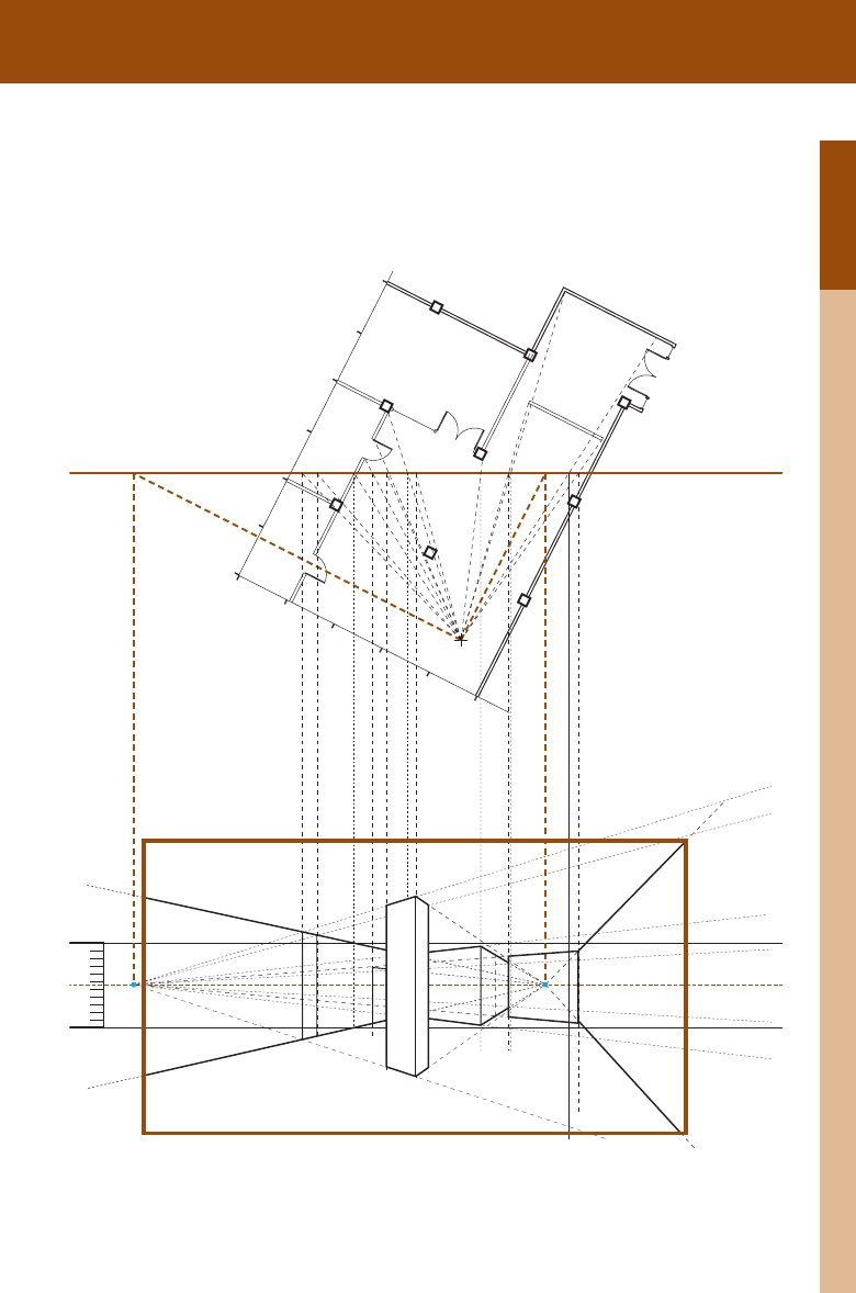
Text
SP
HL
GL
VPL VPR
elevation
with ML
PLAN
PP
height; it is typically projected from the verti-
Represents the intersection
Center of Vision (C):
In a one-point perspec-
tive, a line perpendicular to the horizon line
is drawn from the center of vision to estab-
lish the point to which all lines converge.
Vanishing Point (VP):
Vanishing points in a
two-point perspective are found by projecting
lines parallel to each axis of the plan until
they meet the picture plane. Lines are then
projected perpendicular to the horizon line.
Two-Point Perspective
Job:02-30056 Title: RP-Interior Design Reference and Specification
#175 Dtp:216 Page:47
Job:02-30056 Title: RP-Interior Design Reference and Specification
#175 Dtp:216 Page:46
(RAY)
024-057_30056.indd 47 3/4/13 7:23 PM

03
Job:02-30056 Title: RP-Interior Design Reference and Specification
#175 Dtp:216 Page:48
(RAY)
024-057_30056.indd 48 3/4/13 7:22 PM
4 8
THE INTERIOR DESIGN REFERENCE + SPECIFICATION BOOK
Text
DIGITAL DESIGN SOFTWARE
Perhaps the most challenging and important decision any interior designer can make is the
choice of computational software that will form the basis of their design methodology. Cer-
tainly, the industry acknowledges particular standards; at the same time, several emerging
technologies are beginning to affect the way in which design is thought about, represented,
and produced. These applications have been categorized into the distinct groups that fol-
low—not to suggest an authoritative list, but rather to provide a framework for selecting the
best software to suit an individual practice.
IMAGING SOF TWARE
An increasingly important tool for the interior designer, imaging software allows photographs
and drawings to be manipulated by inserting images of materials, colors, and other elements
(such as furniture, fixtures, or lights). Imaging software is typically used for adding people to
perspectives, indicating zones of a plan, or including details on plans and elevations. Many
applications permit layering, so that different aspects of the design can be emphasized and
alternative schemes explored.
Raster Images
A raster image is a collection of pixels (or points of color) that depend on their resolution for
their integrity. The more pixels in a given image, the greater its resolution, providing more
information about the image displayed on screen. Resolution also determines the size of the
printed image; the greater the resolution, the higher the quality, which allows for a larger print.
A raster image is very memory-intensive, as each pixel and its combination of colors must be
considered in the document. To be saved at smaller sizes, raster images employ compression
techniques that can effect the quality of the image. Such formats are often referred to as
“lossy” because they lose information in the compression of the original.
Raster File Types
TIFF, JPG, GIF, BMP, and PNG are all examples of raster file types. Each has its advantages
and use. TIFFs are not as compressed as JPGs, but have larger files. JPGs and GIFs are use-
ful for displaying images in an on-screen presentation or over the Internet, and PNGs create
smaller files than JPGs while using less compression.
Raster Image Processing
Several applications exist for processing and editing raster images, the most popular of which
is Adobe’s Photoshop. These programs allow users to correct mistakes in an image; add mate-
rial content to perspectives, plans, and sections; and create images entirely from scratch.
A visual depiction of
layers in a raster image.
Layering in 2-D software
allows for the isolation of
specific parts of a draw-
ing, whether it is a sche-
matic image or a working
construction document.
The images adjacent demonstrate the
loss in quality—occasionally referred to
as artifacting—as raster compression
increases.
Job:02-30056 Title: RP-Interior Design Reference and Specification
#175 Dtp:216 Page:48
(RAY)
024-057_30056.indd 48 3/4/13 7:23 PM
..................Content has been hidden....................
You can't read the all page of ebook, please click here login for view all page.