
Micromagnetic simulations of cylindrical magnetic nanowires
Y.P. Ivanov1; O. Chubykalo-Fesenko2 1 King Abdullah University of Science and Technology, Thuwal, Saudi Arabia
2 Instituto de Ciencia de Materiales de Madrid, CSIC, Madrid, Spain
Abstract
This chapter reviews micromagnetic simulations of cylindrical magnetic nanowires and their ordered arrays. It starts with a description of the theoretical background of micromagnetism. The chapter discusses main magnetization reversal modes, domain wall types, and state diagrams in cylindrical nanowires of different types and sizes. The results of the hysteresis process in individual nanowires and nanowire arrays also are presented. Modeling results are compared with experimental ones. The chapter also discusses future trends in nanowire applications in relation to simulations, such as current-driven dynamics, spintronics, and spincaloritronics. The main micromagnetic programs are presented and discussed, together with the corresponding links.
14.1 Introduction
Recent developments in nanofabrication have boosted the experimental study of objects with scales from thousands to tens of nanometers. Such building blocks of the new electronic industry could significantly improve existing technology.
Magnetic cylindrical nanowires (NWs) constitute an example of such nanotechnology. These NWs, with diameters on the order or less than the single domain limit, as well as their arrays, are very attractive for applications in nanoelectronics, energy harvesting, chemical and biological sensing, and medicine (Parkin et al., 2008; Chang et al., 2007; Liao et al., 2006; Kim et al., 2014; Lee et al., 2012; Schroeder et al., 2011; Fung et al., 2008; Song et al., 2010; Safi et al., 2011; Choi et al., 2008, 2012). NWs with diameters as small as 10–20 nm and high aspect ratios can be prepared using electrodeposition into templates, such as nanoporous membranes, which is difficult to achieve using other techniques such as conventional lithographic processes. Another method to grow cylindrical NWs using focused ion beam or electron-assisted deposition was recently developed (Fernandez-Pacheco et al., 2013; Serrano-Ramón et al., 2011; Nikulina et al., 2012).
Understanding the nature of magnetization reversal processes in NWs and their arrays is important for the control of their magnetic properties. Because of the very small sizes of NWs, however, detailed experimental studies require the use of often expensive equipment or large facilities, such as synchrotrons. Experimentally measuring individual cylindrical (not flat) NWs is a nontrivial task. For example, for direct detection of magnetic configuration, three-dimensional (3D) measurements are necessary. Most conventional methods (Magneto-Optical Kerr Effect (MOKE), magnetic force microscopy, Lorenz, electron holography, and Spin resolved Photoemission Microscopy (SPEEM)) record two-dimensional (2D) data. Micromagnetic simulations are a very powerful tool for interpreting such experimental data. Moreover, in many cases they can be used before experiments to predict experimental results or to check the working hypothesis. Nowadays, most problems can be solved using a standard modern personal computer. There also are several software packages available, both open source (Scholz et al., 2003; Donahue and Porter, 2006; Fischbacher et al., 2007) and commercial (Scheinfein, 2003; Berkov, 2007), that can be used to run simulations.
For very small ferromagnetic particles – strictly speaking, with an ellipsoidal form (Aharoni, 2000) and with a size less than the single domain limit – the Stoner–Wohlfarth model for coherent magnetization rotation was developed many years ago. Later, disagreement between this model and experiments showed its limitations for nanoparticles with a high aspect ratio. Coherent reversal also has been investigated as a possible mode for NWs. This mode would correspond to homogeneous rotation of magnetization in unison along the whole length of the NW. Before the use of computers, the curling reversal mode also was suggested and evaluated analytically by Aharoni (1997), a pioneer in micromagnetic theory, based on the cylindrical symmetry property. His analytical theory for magnetization reversal is valid only for homogeneous ferromagnetic prolate spheroids. He calculated the angular dependence of the nucleation field and coercivity of the particles with a high aspect ratio for coherent rotation and curling modes in the case of isotropic and anisotropic ferromagnetic materials. Later the coherent rotation and the curling reversal modes became a paradigm in the magnetization reversal studies of nano-objects, and the experimental results of the angular dependence of coercivity in magnetic NWs are frequently fitted to these models (Fernandez-Pacheco et al., 2013; Vivas et al., 2012a; Salem et al., 2012; Rheem et al., 2007a,b).
The nucleation theory of Aharoni has more recently undergone several generalizations in NW applications. For example, Escrig et al. (2008) generalized the results described by Aharoni, taking into account localized nucleation in the volume of the order of the exchange correlation length. They discussed three main reversal modes for isolated cylindrical NWs, depending on their geometry: coherent rotation, transverse domain wall (TDW), and vortex domain wall (VDW) modes. The TDW and VDW modes correspond to nucleation and propagation of a domain wall (transverse or vortex type) in long NWs. The transition between the latter two modes is expected to occur with the increase in a NW’s diameter (Hertel and Kirschner, 2004). These models were successfully fitted to experiments in several cases (Lavín et al., 2009; Vivas et al., 2012a). For example, the fitting of the experimentally measured angular dependence of coercivity (Vivas et al., 2012a,b) to models based on TDW or curling within a finite volume (similar to VDW) has allowed the coercivity mechanism in Co-based NWs to be associated with the possible occurrence of these processes.
However, analytical calculations based on the aforementioned approach can only qualitatively describe the experimental results (Lavín et al., 2009; Vivas et al., 2012a,b). First, the analytical calculations are based on some predefined form for magnetization distribution, with trial ansatz functions for noncoherent modes. Second, the models simplify or do not consider real geometry, structural characteristics of NWs, or realistic magnetocrystalline anisotropy (MA) and frequently simplify the magnetostatic energy calculation, taking it as, for example, an additional shape anisotropy and disregarding the influence of nonhomogeneous magnetization distribution.
Micromagnetic simulation is a powerful instrument to investigate the magnetization reversal modes in NWs, as well as their ordered arrays (Usov and Peschany, 1993; Hertel and Kirschner, 2004; Hertel, 2002; Lebecki and Donahue, 2010; Vila et al., 2009; Lee et al., 2007; Forster et al., 2002; Vivas et al., 2011, 2013; Bran et al., 2013a,b). These simulations allow the reversal mode to be predicted without any simplifications related to its functional form and magnetostatic fields. The first micromagnetic simulations (Usov and Peschany, 1993; Belliard et al., 1998; Hertel and Kirschner, 2004; Hertel, 2002) corrected the analytical concepts, showing that reversal in NWs never takes place by means of coherent rotation or curling but by the nucleation of domain walls at the ends of NWs and their subsequent depinning and propagation along its length. The domain wall structure is transverse or vortex, depending on the NW’s diameter (Hertel and Kirschner, 2004). A TDW occurs in NWs with a small diameter, whereas for NWs with a larger diameter, the reversal takes place by means of a VDW. In larger micron-size NWs, the reversal modes can have an even more complex structure (Usov et al., 1998; Stoleriu et al., 2012).
Experimental TDWs and VDWs were previously observed in magnetic nanostripes (NWs with a rectangular cross section and relatively small thickness compared with the width and length of the NW) (Boulle et al., 2011). The spin configuration of such NWs can be described in 2D. Strictly speaking, the TDW and VDW spin configurations in NWs with rectangular and cylindrical cross sections are different and should be distinguished. Historically, however, the same names are used. Domain walls in cylindrical NWs have recently been observed by means of X-ray circular magnetic dichroism (Da Col et al., 2014). The understanding of the magnetic structure of these objects is more complicated because of the 3D nature of their spin configuration. To distinguish VDW in 3D from the VDW in nanostripes, Da Col et al. (2014) proposed calling VDWs in cylindrical NWs as “Bloch-point domain walls.” According to Thiaville et al. (2003) and Hertel and Kirschner (2004), domain wall propagation in cylindrical NWs can be described as Bloch-point nucleation and propagation. A Bloch-point is a singularity sitting on the core of a VDW where the magnetization is changed from the up to the down direction; strictly speaking, it passes through zero magnetization. Magnetization reversal through the Bloch point makes the magnetic configuration in such NWs very stable compared to thermal fluctuations because the corresponding energy barrier separating the two states is very high. In addition, it was recently shown that in NWs with strong uniaxial MA, the remanent magnetization can be characterized by the vortex-like configuration in the whole NW, depending on the direction of the magnetocrystalline easy axis with respect to the NW axis (Ivanov et al., 2013a).
This chapter is organized as follows. The theoretical background of micromagnetism is presented in Section 14.2, and some technical aspects related to the finite differences (FDs) and finite element (FE) methods are briefly discussed. Section 14.3 is devoted to a description of the main reversal modes, domain wall types, and state diagrams in cylindrical NWs. In Section 14.4 we describe some results of the hysteresis process in individual NWs and NW arrays. Modeling results are compared with experimental ones. The role of magnetostatic interactions also is discussed. Section 14.5 is devoted to describing future trends in NWs in relation to simulations, such as, the current-driven dynamics, spintronic, and spincaloritronic applications. Future possibilities for modeling microwires using large computer resources and graphic cards are outlined. Main micromagnetic programs and their web pages are highlighted in Section 14.6.
14.2 Micromagnetic model
Micromagnetism is a continuum theory of ferromagnetic materials that allows for the computation of spin configuration of samples with arbitrary shapes. The theory is based on assumptions that the length of the magnetization vector is constant and all energies vary slowly at the atomic scale. Thus this theory is suitable for nano-objects but breaks down when approaching the atomic size. The assumption of the constant magnetization length also restricts the theory at temperatures far from the Curie temperature.
Micromagnetism is based on energy minimization. Most micromagnetic programs either use a direct energy minimization by means of, for example, a conjugate-gradient method or solve the dynamic equation of motion. The dynamics of the magnetization vector in an external magnetic field are described by the Gilbert equation (Brown, 1963a):

where m is the (normalized) magnetization vector, γ0 is the (positive) gyromagnetic ratio, α is the Gilbert damping parameter, and Heff is defined as the effective field. It consists of the external magnetic field and the contributions of the exchange, magnetic anisotropy, and magnetostatic energies. Heff can be represented as the first derivative of the total energy density with respect to the magnetization:

where Ms is the saturation magnetization. The total energy of the ferromagnetic element (particle) includes exchange, magnetic anisotropy, and magnetostatic and Zeeman energy contributions and can be written in the international system of units as follows:

Here, A is the exchange constant, μ0 is the vacuum permeability, Ea is the anisotropy energy, Hdem is the magnetostatic field, and Happ is the external magnetic field. Depending on the type of anisotropy, the second term can be written as
for uniaxial anisotropy, where Ku is the uniaxial anisotropy constant and uk is the unit vector along the anisotropy axis, or
for cubic anisotropy, where K1 and K2 are the cubic anisotropy constants and α, β, and γ are the directional cosines of the magnetization with respect to the cubic easy axes.
For numerical integration, the Gilbert equation (14.1) is converted into the Landau–Lifshitz–Gilbert equation and used in the following form:

The first term on the right-hand side corresponds to the gyroscopic behavior and the angular momentum associated with the interaction between the magnetization and Heff. Dissipation of the energy is given by the second term, often in a phenomenological sense. In the case of hysteresis simulation, this term is introduced to make the system go down to the equilibrium state.
To find the equilibrium state or to solve for the dynamics, a sample with a specific finite shape is divided into cubic cells (FD simulations) or FEs. The magnetization is specified either as the value in the center of the cube (representing the average value over this portion of the volume) or as the value at the nodes. In the latter case, the magnetization inside the element is continuously interpolated. The initial state of all these cells is defined before starting the simulation. The evolution of the system is calculated either by directly minimizing the energy or by integrating the Landau–Lifshitz–Gilbert equation in time for each cell. The calculation is finished when the Brown condition (Brown, 1963b) is reached.
One of the main criteria that have to be rigorously taken into account is the size of the cubic cells or the average size of the FEs. Materials with small anisotropy must be smaller than the exchange correlation length lex of the simulated material, defined as:

Exchange lengths for typical materials, the cylindrical NWs and other relevant parameters are presented in Table 14.1.
Table 14.1
Parameters of typical materials of cylindrical nanowires
| Material (reference) | Crystal structure | A (J/m) | Ms (T) | lex (nm) | Anisotropy type | Easy axis (θ; φ; ψ) (rad) | Ka (J/m3) |
| Py(Fe80Ni20) (Smith et al., 1989) | Polycrystalline | 1.05 × 10− 11 | 1.0 | 5.1 | – | – | 0.0 |
| Ni(111) (Liu et al., 2005) | FCC, [111] | 0.34 × 10− 11 | 0.61 | 4.8 | Cubic | [111] (0.96; 0; 0.61) | − 0.048 × 10⁵ |
| Fe(110) (Liu et al., 2005) | BCC, [110] | 0.81 × 10− 11 | 2.15 | 2.1 | Cubic | [110] (0; 0; 0) | 0.48 × 10⁵ |
| Fe(100) (Liu et al., 2005) | BCC, [100] | 0.81 × 10− 11 | 2.15 | 2.1 | Cubic | [110] (0.79; 0; 0) | 0.48 × 10⁵ |
| Co(111) (Fisher, 1970) | FCC, [111] | 1.30 × 10− 11 | 1.75 | 3.3 | Cubic | [111] (0.96; 0; 0.61) | − 2.7 × 10⁵ − 0.75 × 10⁵ |
| Co(100) (Cullity, 1972) | HCP, polycrystalline, texture (100) | 1.30 × 10− 11 | 1.75 | 3.3 | Easy plane, | Random 2D in plane | 4.5 × 10⁵ |
| Co-hcp (Cullity, 1972) | HCP, polycrystalline | 1.30 × 10− 11 | 1.75 | 3.3 | Easy axis in each grain | Random 3D | 4.5 × 10⁵ |
| Fe80Co30 (Bran et al., 2013a) | BCC, polycrystalline | 1.08 × 10− 11 | 2.0 | 2.6 | Easy axis in each grain | Random 3D | 0.1 × 10⁵ |
| Fe86Ga14(100) (Reddy et al., 2011) | BCC, [110] | 2.06 × 10− 11 | 1.6 | 4.5 | Cubic | [110] (0.0; 0.0; 0.0) | 0.3 × 10⁵ |
The direction of cubic anisotropy is characterized by the Euler angles (θ, φ, ψ) (rad), where θ and φ are angles that form the magnetocrystalline anisotropy axes in spherical coordinates with x- and y-axes and the z-axis coincides with the nanowire axis; ψ is the third Euler angle.
The most time-consuming part of micromagnetic simulations is the calculation of the magnetostatic field. Much effort has been devoted to developing efficient methods for calculating the magnetostatic contribution. Nowadays there are several approaches. The most frequently used ones are the FE method–boundary element method, used for FEs, and the fast Fourier transform, or the fast multipole expansion method, used for FD. The important practical difference between the FE and FD methods is the possibility to treat curved geometries, which are better suited to FEs. Figure 14.1 shows the examples of FE and FD meshing in cylindrical NWs. Clearly, FE discretization is more suitable for modeling NWs with a cylindrical geometry.

In addition, for a meaningful micromagnetic model, the appropriate crystal structure in terms of the type of MA, its constant value, and easy axis directions and distribution must be taking into account. The parameters of typical materials of cylindrical NWs are presented in Table 14.1. Note that the so-called shape magnetic anisotropy is a part of the magnetostatic energy and thus should not be included explicitly into the anisotropy term. This makes it difficult to extract the anisotropy parameter from the hysteresis cycle measurements because the so-called effective anisotropy is the sum of all possible contributions, including those of the magnetocrystalline and the “shape.” The quantitative agreement between simulation data and experimental data strongly depends on the inclusion of a realistic experimental nanostructure and parameters into the model (Vivas et al., 2013; Ivanov et al., 2013a).
Micromagnetic simulations are very demanding in terms of computer resources. The first resource is the amount of random access memory (RAM) available in the computer system. Because the cell size must be around a few nanometers, a large structure can significantly increase the number of cells and, consequently, the RAM needed. NWs with a 40-nm diameter and a 2-μm length may consume up to 1 Gb of RAM. The model used in FE packages precalculates the magnetostatic energy matrix and requires even more RAM. To keep at a minimum the time required to simulate a large structure, the processor must be able to fully access the data in RAM as fast as possible. Thus, to minimize the time necessary for a simulation, the use of parallel computing is desirable. The major micromagnetic programs used today have parallel versions.
14.3 Reversal modes in cylindrical NWs
First let us discuss the reversal modes of NWs with negligible or very small MA. These correspond to NWs with a polycrystalline structure or single crystal NWs with a cubic anisotropy, such as permalloy or nickel (Ni) NWs. Figure 14.2 shows a reversal mode diagram (Ivanov et al., 2013b) presented in terms of the NW diameter and the material type (defined by the exchange correlation length) calculated by the MAGPAR FE micromagnetic package. The NWs are represented as cylinders with a 2-μm fixed length, and diameters vary from 20 to 100 nm, thus saving the high aspect ratio of NWs, which therefore exhibit strong shape anisotropy. They are discretized in a tetrahedral mesh, and the magnetization orientation is computed on each mesh vertex. The structure, anisotropy, and magnetic parameters of NWs are shown in Table 14.1. To simulate polycrystalline NWs, a random orientation of the magnetocristalline easy axis in each tetrahedral has been considered. The average FE discretization size was chosen as 4 nm.

The magnetization reversal of NWs with a polycrystalline structure or with single-crystalline cubic anisotropy is mostly determined by the shape anisotropy because of its high value with respect to the average magnetocrystalline structure. This high value is caused by the high aspect ratio length/diameter. Typical hysteresis loops for a magnetic field applied parallel ![]() and perpendicular
and perpendicular ![]() to the NW axis are presented in Figure 14.3. For the
to the NW axis are presented in Figure 14.3. For the ![]() case, the loop has a rectangular shape and magnetization reversal occurs because of domain wall propagation. The type of domain wall changes from a TDW to a VDW, depending on the lex and the NW’s diameter. For example, for iron NWs, only VDWs are observed, whereas for cobalt (Co) NWs the transition occurs at a 20-nm diameter and for Py NWs at a 40-nm diameter. The transition from a TDW to a VDW in cylindrical NWs was recently experimentally observed by electron holography (Biziere et al., 2013) and X-ray magnetic circular dichroism–photoemission electron microscopy (Da Col et al., 2014), in good agreement with the diagram presented in Figure 14.2. The remanence is the single domain state in which the magnetization is aligned along the NW axis. Only at the NW’s ends does the spin form a vortex-like configuration – a so-called open vortex structure. The length of this area at the ends is also dependent on the material. It is larger for materials with a smaller lex and increases with the NW diameter. In particular, one should remember that the formation of such structures at the NW’s ends, minimizing the magnetostatic energy, does not allow the shape anisotropy to be estimated using simple analytical expressions. Figure 14.3 shows the structure of the domain walls and open vortex structure at the remanence.
case, the loop has a rectangular shape and magnetization reversal occurs because of domain wall propagation. The type of domain wall changes from a TDW to a VDW, depending on the lex and the NW’s diameter. For example, for iron NWs, only VDWs are observed, whereas for cobalt (Co) NWs the transition occurs at a 20-nm diameter and for Py NWs at a 40-nm diameter. The transition from a TDW to a VDW in cylindrical NWs was recently experimentally observed by electron holography (Biziere et al., 2013) and X-ray magnetic circular dichroism–photoemission electron microscopy (Da Col et al., 2014), in good agreement with the diagram presented in Figure 14.2. The remanence is the single domain state in which the magnetization is aligned along the NW axis. Only at the NW’s ends does the spin form a vortex-like configuration – a so-called open vortex structure. The length of this area at the ends is also dependent on the material. It is larger for materials with a smaller lex and increases with the NW diameter. In particular, one should remember that the formation of such structures at the NW’s ends, minimizing the magnetostatic energy, does not allow the shape anisotropy to be estimated using simple analytical expressions. Figure 14.3 shows the structure of the domain walls and open vortex structure at the remanence.

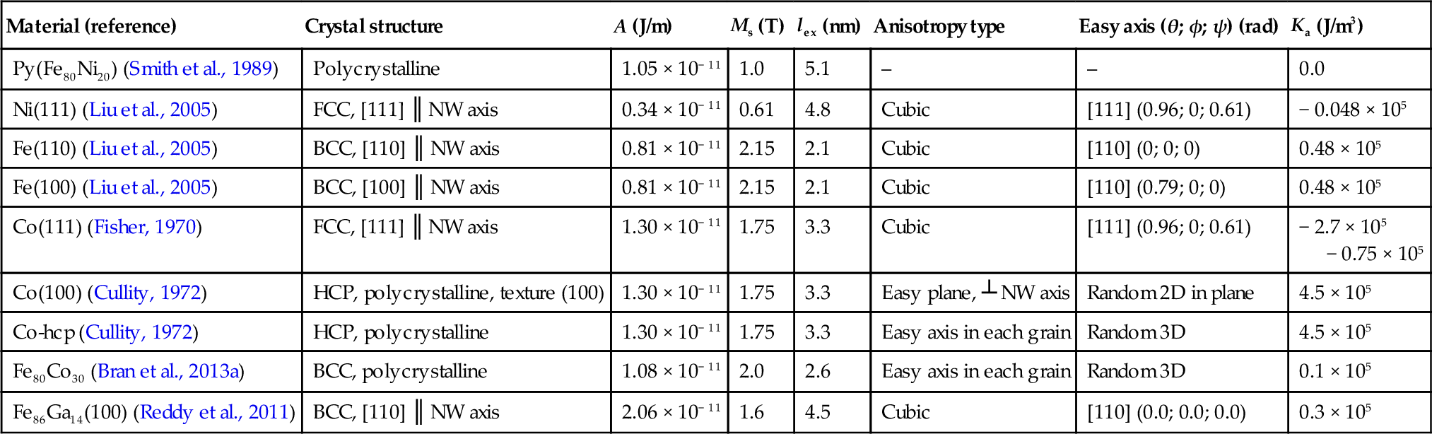
Figure 14.4 shows the coercivity Hc and the reduced remanence Mr/Ms as a function of the NW diameter in the case of a magnetic field applied parallel (![]() ) to the NW axis, simulated for a series of NWs with different crystalline structures. Mr/Ms is slightly reduced with the NW diameter, and this effect is a bit more pronounced for materials with smaller lex. It is connected with the aforementioned appearance of an open vortex area at the NW’s ends.
) to the NW axis, simulated for a series of NWs with different crystalline structures. Mr/Ms is slightly reduced with the NW diameter, and this effect is a bit more pronounced for materials with smaller lex. It is connected with the aforementioned appearance of an open vortex area at the NW’s ends.
As shown in Figure 14.4a, for all NWs, the coercivity decreases with an increase in the NW diameter as it corresponds to a decrease in the shape anisotropy, which scales with the length-to-diameter ratio. Note that for the smallest diameters, the coercivity of Co and Py NWs is twice as large as that of Ni and iron NWs, which is related to the change in the magnetic reversal mode, as shown in Figure 14.2a. In general, the coercivity value for the TDW mode is higher than for the VDW mode. A similar effect can be observed for the same material and a fixed NW diameter under, for example, annealing. Bran et al. (2013b) reported that the coercivity of CoFeCu NWs was increased after annealing at 500 °C, which can be attributed to a decrease in the Ms value and, consequently, an increase in lex. and the transition of the reversal mode from VDW to TDW.
The data presented in Figure 14.4 are in a good agreement with those reported in the literature describing experimental data for NWs with the same geometry and crystal structure (Table 14.2). Small discrepancies between experimental results and our micromagnetic simulations can be attributed to the change in MA caused by the different crystal quality of NWs prepared at different electrodeposition conditions. Also, as shown in Figure 14.4, for iron NWs with different easy axis orientations and for Co NWs, the coercivity value cannot change too much with the crystal quality of NWs, especially for NWs with diameters larger than 50 nm. Our simulations show that the change in cubic anisotropy thrice, as presented in Table 14.1, does not affect too much the magnetic properties of face-centered cubic Co NWs. The data presented in Figure 14.4 can be also applied to NWs based on iron, Co, and Ni alloys, taking into consideration that the correct simulation parameters can be varied depending on the alloy composition (Bran et al., 2013a) and would change slightly the resulting coercivity value.
Table 14.2
Comparison between simulated coercivity values in various nanowires with those reported in the literature
| Material | d (nm) | Aspect ratio | Length (nm) | Hc (Oe) | |
| Simulation | Experiment | ||||
| Py(Fe80Ni20) | 35 | 60 | 2000 | 1900 | 1232 (Navas et al., 2005) |
| 40–70 | 80 | 5000 | 1620–670 | 1436–700 (Salem et al., 2012) | |
| Ni(111) | 20 | 50 | 1000 | 1900 | 970 (Zheng et al., 2000) |
| 35 | 60 | 2000 | 1350 | 780 (Navas et al., 2005) | |
| 30 | 30 | 700 | 1550 | 1200 (Nielsch et al., 2002) | |
| 50 | 240 | 12,000 | 927 | 624 (Escrig et al., 2008) | |
| 30–100 | 20 | 2000 | 1550–290 | 1150–300 (Fert and Piraux, 1999) | |
| 30, 40, 55 | 20 | 1000 | 1620, 1255, 740 | 1200, 1000, 600 (Nielsch et al., 2001) | |
| 180 | 20 | 3400 | 290 | 215 (Escrig et al., 2007) | |
| 50 | 1000 | 50,000 | 927 | 1000 (Pan et al., 2005) | |
| Fe(110) | 70 | 20 | 1000 | 555 | 550 (Haehnel et al., 2010) |
| 20 | 50 | 1000 | 2500 | 2250 (Sellmyer et al., 2001) | |
| 80 | 70 | 5000 | 455 | 450 (Wang et al., 2004) | |
| 30 | 170 | 5000 | 1700 | 1720 (Wang et al., 2004) | |
| Fe(100) | 35 | 120 | 4000 | 1245 | 1250 (Yang et al., 2000) |
| 20 | 200 | 4000 | 2321 | 2311 (Paulus et al., 2001) | |
| Co(111) | 40 | 10 | 120 | 1790 | 1730 (Vazquez and Vivas, 2011) |
| 40 | 130 | 5000 | 1790 | 1760 (Zhang et al., 2007) | |

In the case of a magnetic field applied perpendicular ![]() to the NW axis, the magnetic behavior of NWs is practically nonhysteretic (Figure 14.2b) and magnetic parameters are almost independent of the NW diameter. The reversal mode is the quasi-coherent rotation. The spins on the open vortex area do not follow the direction of the applied magnetic field simultaneous with those in the inner structure.
to the NW axis, the magnetic behavior of NWs is practically nonhysteretic (Figure 14.2b) and magnetic parameters are almost independent of the NW diameter. The reversal mode is the quasi-coherent rotation. The spins on the open vortex area do not follow the direction of the applied magnetic field simultaneous with those in the inner structure.
MA can be used as an efficient instrument to control the magnetic behavior of cylindrical NWs (Vivas et al., 2013; Ivanov et al., 2013a; Henry et al., 2001; Liu et al., 2008). To efficiently control magnetic properties via engineering of the MA, its constant should be large enough to compete with the shape anisotropy in NWs with a high aspect ratio. Because the strength of the MA is strongly affected by the crystal quality of the NWs, the best samples to compare with theory are single-crystalline NWs. For example, Co NWs frequently show a preferential, almost single-crystal, hexagonally close-packed (HCP) crystallographic structure (Pan et al., 2005; Henry et al., 2001; Liu et al., 2008). The presence of such a crystal phase leads to a noticeable uniaxial MA of the same order of magnitude (4.8 × 10⁵ erg/cm3) as the shape anisotropy. Depending on the orientation of the MA easy axis with respect to the NW axis, the MA can both increase and decrease the effective anisotropy of NWs. Consequently, the magnetic properties of Co NWs can be tuned by modifying the direction of crystal growth (Vivas et al., 2012b; Vazquez and Vivas, 2011; Henry et al., 2001) or the NW composition (Co-based alloy NWs) (Vivas et al., 2012a; Bran et al., 2013a; Vega et al., 2012).
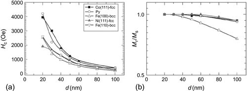
Figure 14.5a shows a diagram of domain wall type as a function of the NW diameter for an HCP single-crystalline Co NW in a parallel-field configuration. Single-crystal NWs with an orientation of the MA easy axis (c-axis) at different angles θ with respect to the NW axis have been considered. Strong uniaxial MA in single-crystalline, HCP-based NWs significantly affects the magnetic reversal mode.
The TDW reversal mode is stabilized by MA with an easy axis at 0° ≤ θ ≤ 60° in the whole range of NW diameters. In a perpendicular-field configuration the quasi-coherent rotation mode is observed.
For 70° < θ < 90° there is a transition between the two wall types, and the transition diameter decreases significantly with θ. Note that for the narrowest NWs (20-nm diameter), the reversal mode is TDW propagation independent of the MA easy axis orientation.
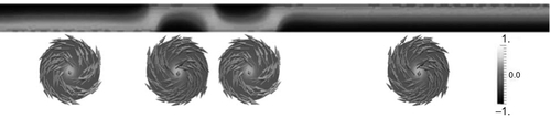
Another transition for the reversal mode can be induced by MA with an easy axis at 60° ≤ θ ≤ 90° for Co NWs with large diameters. Here, a quasi-curling reversal mode appears (shown as crossed triangles in Figure 14.5a). In that case, the spins at the remanence form a vortex-like state along the whole length of the NW (Figure 14.6), with a core parallel to the initial applied field direction in a parallel configuration or randomly oriented up/down in a perpendicular configuration. Because of the high aspect ratio of NWs, there are several vortices with alternating chiralities (clockwise/counterclockwise) along the NW length (Figure 14.6). Note that for a perpendicular configuration, the number of vortices is larger than for a parallel configuration. The same transition is also observed for textured Co(100) HCP NWs with the easy plane anisotropy in-plane of the NW diameter (Ivanov et al., 2013b). The corresponding mode is called quasi-curling because of the different speeds of curling at the NW ends and in the center. The core of the vortex is remagnetized by domain wall nucleation and propagation.
Typical hysteresis loops simulated for NWs with competing shape and magnetocrystalline anisotropies are presented in Figure 14.5b. As shown in Figure 14.7, the magnetic behavior of Co HCP NWs strongly depends on θ in the interval between 75 and 90°. For θ < 70°, the MA reinforces the shape anisotropy. When the field is applied parallel to the NW axis, the coercivity is increased when compared with polycrystalline NWs and decreases practically linearly with the NW diameter (Figure 14.7a), following the behavior of the shape anisotropy. At θ > 70°, the MA tends to compensate for the shape anisotropy, and both the coercivity and the remanence decrease drastically with the NW diameter. The strong decrease in remanence is associated with the formation of a vortex state along the whole NW length (Figure 14.6). Note that the existence of a vortex state along the whole NW was recently confirmed by magnetic force microscopy measurements (Ivanov et al., 2013a). The tilt of the anisotropy with respect to the NW axis makes the vortex structure lose its circular symmetry and produces magnetic charges visible on magnetic force microscopy.

The angular dependence of coercivity is commonly used to elucidate the occurrence of different magnetic reversal modes in NWs (Fernandez-Pacheco et al., 2013; Lavín et al., 2009; Vivas et al., 2012a; Salem et al., 2012; Rheem et al., 2007a,b). For this purpose, the magnetic loops are measured at the different directions of the applied magnetic field with respect to the NW axis (defined by the angle α) for hexagonal ordered NW arrays (Lavín et al., 2009; Vivas et al., 2012a; Salem et al., 2012) or single NWs (Fernandez-Pacheco et al., 2013; Rheem et al., 2007a,b). After that, the data can be fitted using the analytical expressions for the nucleation field (Lavín et al., 2009; Vivas et al., 2012a; Salem et al., 2012; Rheem et al., 2007a,b). Specifically, based on analytical models, Vivas et al. (2013) concluded that the transition between TDW and VDW modes in Co–Ni alloy NWs is a function of the applied field angle.
Another approach is to use micromagnetic simulation with realistic model parameters (geometry, material properties, MA). The angular dependence of the critical fields (nucleation field Hn and coercivity Hc), as well as the remanence Mr/Ms, for NWs with different reversal modes were simulated by Ivanov et al. (2013b), based on Py, Fe(110), and Co (easy axis angle θ = 88°) with a 40-nm diameter, as well as a hexagonal ordered array of seven NWs with a center-to-center distance between NWs of 105 nm. According to the diagram in Figure 14.2a, the reversal mode corresponds to the TDW propagation for Py, VDW propagation for Fe(110), and the quasi-curling mode for Co NWs when the field is applied parallel to the NW axis. In simulations with a field applied at different angles, the type of reversal mode did not change with the applied field angles, except for an exact value of α = 90°, when the TDW or VDW mode was changed to a quasi-coherent rotation mode.
Importantly, the simulations showed the differences between the angular dependence of the nucleation and the coercivity fields Hn and Hc. For large applied field angles, Hc is not equal to Hn, in agreement with the experimental data reported by numerous authors (Escrig et al., 2008; Yang et al., 2000; Paulus et al., 2001). The angular dependence is the same in the range of the applied field angles 0° ≤ α ≤ 60°. For 60° ≤ α < 90°, however, the two fields are different: the Hn starts to increase, whereas the Hc decreases. The angular dependence of Hc is similar to the curling reversal mode, although VDWs or TDWs occur for all angles. Based on an analytical formula, the functional dependence of coercivity in CoNi NWs has been interpreted as a change of the reversal mode from TDW to VDW at 60° (Vivas et al., 2012a), whereas micromagnetic simulations report the same trend but do not show such a transition.
Finally, we summarize the type of the domain walls in cylindrical NWs extracted from micromagnetic simulation (Ivanov et al., 2013b). For NWs with a weak MA (polycrystalline NWs or single-crystal NWs with a cubic anisotropy), two types of the DW dominate: TDW and VDW (called also the Bloch-point domain wall). Both of them can be also in head-to-head or tail-to-tail configurations. NWs with a 3D vortex structure along the whole NW length (single-crystal HCP Co NWs) present two different domain walls at the interface between two vortices with opposite chiralities of the vortex shell or polarities of the vortex core: chirality to chirality or polarity to polarity. The orientation of the spins in the region between two vortices (domain walls) with opposite chirality or polarity depends on the type of MA. For single-crystal HCP Co NWs, the spins in the center of the domain wall are aligned parallel to the easy axis direction (c-axis), whereas for polycrystalline HCP Co NWs, governed by shape anisotropy, the spins in the center of the domain wall are directed parallel to the NW axis. These types of domain walls are also called helical domain walls in the literature (Sekhar et al., 2012).
14.4 Simulation of hysteresis in individual NWs and NW arrays
The most promising application of cylindrical NWs is NW assembly in ordered arrays. Therefore, the question about dipole–dipole interaction between NWs becomes very important. Most reported arrays are hexagonal with the following typical diameters/interpore distances: 20–40 nm/55 nm, 35–80 nm/105 nm, and 120–200 nm/200 nm.
The strength of dipole–dipole interactions in ensembles of nanomagnets is frequently estimated by measuring the first-order reversal curves (Mayergoyz, 1985; Stancu et al., 2003; Spinu et al., 2004). In particular, first-order reversal curve analysis used by Vivas et al. (2012a) indicated the presence of intense dipolar magnetic fields for Co NWs when compared with CoNi NWs. The authors attributed this effect to the increase in axial anisotropy caused by the addition of Ni.
Theoretical calculation of the magnetostatic field in NW arrays is complicated because of the inhomogeneous spin structure of the NWs and its change in an applied magnetic field. In the case of homogeneously magnetized NWs whose magnetic behavior is determined by shape anisotropy, a magnetostatic interaction between up to 70,000 NWs has been calculated numerically, assuming each NW as one macrospin pointed up or down (Escrig et al., 2008). In a real array, the situation is more complicated, mostly because of the specific magnetic structure of each NW in the array. Clearly, the magnetic state of the NW should influence the strength of the magnetostatic interactions. Indeed, the vortex state presents practically no surface charges, and thus the magnetostatic interactions between NWs are substantially reduced. Similarly, the presence of an open vortex structure, such as those presented in Figure 14.3a, at the end of a NW that is mostly magnetized along its length should considerably reduce the magnetic flux when compared with idealized homogeneously magnetized NWs such as those discussed above. This also invalidates the use of the demagnetization factor approach to include magnetic interactions in consideration.
Micromagnetic simulation is a potentially ideal instrument to estimate the magnetostatic interaction inside a NW array. The number of NWs that can be taken into account is, however, very limited by the computational power. Thus most simulations have been performed in individual NWs or an array of seven NWs. Calculations of arrays of up to 49 NWs is reasonably possible using parallel computers. However, the influence of interactions can be seen in the modeling of just seven NWs. Our experience shows that parallel loops are only slightly modified by the presence of interactions, for example, in terms of the saturating field value. The perpendicular (i.e., in-plane), hysteresis loops, however, are very sensitive to interactions because of the influence of the thin-film geometry, producing an additional “thin film” anisotropy.
Figure 14.8 shows the hysteresis loop simulated for an individual NW and a hexagonal ordered array of seven NWs. The NW diameter (D) is 40 nm and the interwire distance is 105 nm. In general, if the distance between NWs is larger, the magnetostatic interaction is practically negligible. The coercivity and the remanence of a single NW and a NWs array are only slightly different. More inclined magnetic loops are calculated in the array compared with the individual NW for NWs with strong competition between MA and shape anisotropy (Figure 14.8c and d), which indicates a stronger interaction between NWs, in contrast to the case of NWs in which magnetic behavior is determined only by the shape anisotropy (Figure 14.8c and d). The calculated angular dependence of the coercivity and the remanence for single NWs and NWs arrays are also quite similar.

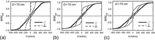
When the ratio between the diameter and interpore distance decreases, the magnetostatic interactions become more important. In general, the experimental value of the coercivity of the arrays is less than the coercivity of a single NW (Vega et al., 2012). An experimental loop of arrays of NWs with dominant shape anisotropy is inclined (Nielsch et al., 2001; Paulus et al., 2001; Pan et al., 2005; Liu et al., 2008; Escrig et al., 2008; Vivas et al., 2012a; Salem et al., 2012) and does not show the one-step magnetization reversal process that occurs for a single NW with the magnetic field applied parallel to the NW axis. Such behavior is also reproduced in micromagnetic simulations. Figure 14.9 shows the magnetic loops calculated for arrays of Co nanopillars with a 75-nm diameter and 120-nm length. After taking into account the random distribution of the MA direction and the increase in the number of nanopillars in the array (up to 49), the simulated loops fit very well the experimentally observed behavior (Vivas et al., 2013).
Simulations should take into account the fact that NWs differ by defects introduced that promote slightly different nucleation fields. If NWs are modeled as granular with random easy distribution, this is automatically achieved. Modeling of individual or a small number of NWs, however, can produce steps in hysteresis loops that are not observed experimentally. The magnetostatic interactions normally smooth the hysteresis curve and make the distribution of individual nucleation fields wider, which significantly changes the coercivity and remanence of the array. By choosing the correct parameters and a sufficient number of simulated NWs, the experimental magnetic behavior the NW array can be successfully reproduced by micromagnetic simulation.
14.5 Future trends
Nowadays, new technological perspectives are opened based on the control of magnetic states in magnetic nano-objects by a spin-polarized current rather than by a magnetic field. In this direction, cylindrical magnetic NWs attract significant interest because of their high potential in the development of novel memory devices constructed in 3D, which can significantly increase the density of the memory. In addition, magnetic-based RAM is expected to have much lower power consumption. Several micromagnetic studies have been performed to predict the most promising properties of cylindrical NWs in terms of the aforementioned application.
Using micromagnetic simulation, Yan et al. (2010) showed that the current-induced motion of TDWs in cylindrical NWs is fundamentally different from that in magnetic nanostripes. Domain wall velocity in nanostripes is limited by the Walker breakdown phenomena. At some critical external magnetic field or electric current, the periodical transformation of the domain wall occurs (TDW to VDW and vice versa), and it slows the domain wall propagation. Micromagnetic simulations showed that intrinsic pinning and the Walker limit do not exist for TDWs in cylindrical NWs; this was attributed to a vanishing domain wall mass. The velocity of TDWs in a cylindrical NW simply depends linearly on the current density. Also, a new method for the measurement of the nonadiabatic spin transfer torque parameter has been predicted based on the characteristics of the field- and the current-induced domain wall dynamics in cylindrical NWs.
Wu et al. (2014) proved the linear dependence of the domain wall velocity on the current density and the absence of the Walker breakdown in the case of multiple current-induced TDW motion in cylindrical NWs by micromagnetic simulation. With an increase in the diameter, the linear velocity of TDW decreases correspondingly; but with a decrease in the damping factor, the linear velocity increases. The results of micromagnetic simulations demonstrated that multiple current-induced TDW motion in cylindrical NWs provides an ideal way to control the domain wall motion in magnetic nanodevices.
As we showed in the previous sections, there are two types of domain walls in cylindrical NWs, depending on the NW diameter: For thinner NWs the TDW is favorable, whereas thicker NWs favor VDWs (or a Bloch-point domain wall). Piao et al. (2013) recently studied micromagnetically the dynamics of VDWs in cylindrical NWs. A feature of this type of domain wall is the presence of a topological singularity in its center, a Bloch-point structure (Hertel and Kirschner, 2004). Actually, it is a complex 3D spin structure that is basically composed of two magnetic vortex structures with head-to-head or tail-to-tail vortex cores. Topological singularities such as skyrmions recently attracted a lot of interest because of their promising application in data storage devices (Sampaio et al., 2013). In particular, Piao et al. (2013) found that there exists an intrinsic depinning field that triggers VDW motion in cylindrical NWs. The VDW propagates with a sequential single precessional switching of the Bloch-point core spin in a few picoseconds, whereas a very fast VDW speed (up to 2000 m/s) is possible while maintaining the structure of the domain wall.
A promising issue on the way to realizing 3D memory devices based on cylindrical NWs is the creation of periodic potential along a NW for domain wall pinning. Using micromagnetic simulations, Franchin et al. (2011) studied in detail the effect of pinning sites (with a size much smaller than that of the domain wall) on the field- and current-driven domain wall motion in cylindrical NWs. In particular, they determined the critical fields and current densities required to push the domain wall through the barrier for various directions of pinning potential. The critical applied field decreases as the pinning direction becomes orthogonal to the NW axis. Importantly, the critical current density increases by more than a factor of 130 when the pinning direction becomes orthogonal to the NW axis.
The ordered arrays of multilayered cylindrical NWs are also very attractive for applications in a new generation of microwave devices based on arrays of the spin-torque nano-oscillators (Kiselev et al., 2003; Kaka et al., 2005; Dussaux et al., 2010). Micromagnetic simulation of multilayered Co/Cu/Co NWs (Abreu Araujo et al., 2012) showed that, depending on the field amplitude and the injected direct current, there appear particular magnetic configurations involving either a one-vortex state or a two-vortex magnetic state. The two-vortex states were the most promising as microwave signals, originating from the giant magnetoresistance effect, and can be obtained without any static bias magnetic field. Recent experiments show this in electrodeposited Co/Cu/Co NWs embedded in Aluminum Oxide Template (AOT) (Abreu Araujo et al., 2013).
Nowadays, a new field in magnetism, so-called spincaloritronics, has received particular attention in the scientific community (Bauer et al., 2012). This is the combination of thermoelectric effects with spintronics and nanomagnets. Thermal effects can be used to generate new functionalities in future spintronic devices. A challenge for device physics is the development of efficient devices for scavenging waste heat. Another issue is the imminent breakdown of Moore’s law by the thermodynamic bottleneck: Further decreases in feature size and transistor speed occur in parallel with intolerable levels of ohmic energy dissipation associated with the motion of electrons in conducting circuits. Thermoelectric effects in nanostructures might help. Spincaloritronics studies the following phenomena: spin-dependent Seebeck/Peltier coefficients and thermal conductance, thermal spin-transfer torques, spin and anomalous thermoelectric Hall effects, the recently discovered spin Seebeck effect, and others. The first experimental measurements of the Seebeck coefficient in single cylindrical NWs was recently reported (Böhnert et al., 2013). Micromagnetic studies are not a trivial task in that case because of the thermal effects. Most now focus on 2D nanostructures such as Py nanostripes (Hinzke and Nowak, 2011). However, the correct introduction of heating in micromagnetic simulations cannot be done based on standard micromagnetic codes because of the assumption of a constant magnetization length. A micromagnetic approach based on the Landau–Lifshitz–Bloch (LLB) equation (Garanin, 1997; Chubykalo-Fesenko et al., 2006) may be an option to overcome this limitation. An extension of Object-Oriented MicroMagnetic Framework micromagnetic code for the LLB equation was recently created. Lebecki et al. (2012) showed that the LLB equation is more suitable for Bloch-point simulation than standard micromagnetics. This opens a new possibility for modeling domain wall propagation in cylindrical NWs moved by thermal gradients.
14.6 Further information
14.6.1 Main micromagnetic programs
Nowadays several micromagnetic packages are available, both open source (Scholz et al., 2003; Donahue and Porter, 2006; Fischbacher et al., 2007) and commercial (Scheinfein, 2003; Berkov, 2007), allowing researchers to run their own simulations.
One of the frequently used public programs and tools for micromagnetics is the Object-Oriented MicroMagnetic Framework (OOMMF) developed by the Applied and Computational Mathematics Division of the National Institute of Standards and Technology (Gaithersburg, MD). The code is written in C++ with a Tcl/Tk. OOMMF can be run in a wide range of Unix platforms and the Windows operating system. The open-source scripting language Tcl/Tk is required to run OOMMF. The available free version is not parallel and a solution runs on only one CPU; a parallel version is being developed. With regard to the simulation of cylindrical NWs, OOMMF allows a wide type of problems to be calculated, such as magnetic loops, domain wall dynamics, multilayer structure, and local fields. By using special plugins, it is possible to calculate current-driven dynamics and, in the near future, thermal effects. For cylindrical NWs the 3D solver and a UNIX operation system must be used. OOMMF is based on the FD approach and the fast Fourier transform for magnetostatic field calculations. The model is completely symmetric and needs to take into account the effect of the edges because of the cubic mesh of cylindrical NWs.
OOMMF is available from: http://math.nist.gov/oommf/.
By comparison, another freely available micromagnetic tool is MAGPAR (Parallel Finite Element Micromagnetics Package) developed by Werner Scholz. This software is an intrinsically parallel code and consequently can be run on several CPUs. A modern working station with 12 CPUs and 64 Gb RAM allows the simulation of, for example, NWs arrays (40- to 80-nm diameter, 1- to 2-μm length, and 7–19 NWs in the array) in quite a reasonable period of time. Other advantage is the FE approximation. The model uses the FE’s tetrahedral mesh. There is no problem with the NW’s shape or intrinsic model symmetry; because of the distribution of the sizes of the elements, it better reproduces the experimental results. The MAGPAR package can be run only on UNIX platforms. Also, special software for meshing and visualization are needed.
MAGPAR is available from: http://www.magpar.net/static/magpar/doc/html/index.html/.
Nmag1 is a free, open-source micromagnetic simulation suite developed by Hans Fangohr’s group at Southampton University (http://nmag.soton.ac.uk). Like MAGPAR, Nmag is based on a FE discretization of space and has the same advantages of a more accurate description of noncuboidal shapes over FD approaches, as well as the same disadvantages that mesh creation needs to be taken care of separately. Nmag is less tuned for performance than MAGPAR; instead it provides greater flexibility in its usage. An Nmag simulation script is a Python program that makes use of the Nmag library and thus allows arbitrary scripted loops, decisions, saved data, and postprocessing to be used or carried out. Additional features include efficient data storage (binary compressed) in hdf5 files and extraction into vtk files, support for arbitrary crystal anisotropy, periodic boundary conditions through the “macro geometry approach” in one, two, and three dimensions, spin torque transfer terms, and postprocessing tools for magnonics. Nmag supports use of the matrix compression library (HLib) for the boundary element matrix. One of Nmag’s great strengths is the extended documentation and tutorials available.
Another frequently used commercial software is the LLG Micromagnetics Simulator, developed by Michael R. Scheinfein. This package has a very friendly graphic interface on a Windows operating system. The most recent version is partially parallel. This software is very suitable for current-driven dynamics, simulation of the spin-transport phenomena, and ferromagnetic resonance measurements. The visualization part includes the possibility to simulate contrast produced by magnetic force microscopy.
The LLG Micromagnetics Simulator is available from: http://llgmicro.home.mindspring.com/AboutLLGFrame.htm/.
Another popular commercial micromagnetic software2 is MicroMagus, developed and maintained for more than 15 years by Dmitry Berkov and Natalia Gorn. The package was initially intended for simulations of thin-layer systems only, but later it was extended by the ability to study nanostructured elements of an arbitrary shape. The CPU version of the software is parallelized and takes full advantage of multicore processor architecture; a GPU version also was recently released. The standard package for Windows contains an intuitive and simple, user-friendly interface; the version for Linux (without such an interface but with detailed instructions on how to write the input files using any text editor) is available on demand. MicroMagus is a completely standalone tool, that is, it does not require any additional software to run it or to visualize the results (magnetization configurations obtained during simulations are saved into .bmp files as color maps). The package uses a specially optimized energy minimization method for quasistatic simulations and advanced versions of Runge–Kutta methods with adaptive step-size control for dynamic simulations (including thermal fluctuations). MicroMagus is a FD package. On the one hand, this feature allows the use of the great acceleration provided by fast Fourier transform for evaluating magnetodipolar fields and a simple high-accuracy approach for computing exchange fields. On the other hand, this leads to standard difficulties in approximating the cylindrical form of NWs by rectangular grid elements. In simulations with MicroMagus, however, the approximation of shapes with curved borders can be substantially improved using rectangular elements, with “partial” magnetization values assigned to those elements that cross the border of the ferromagnetic body being studied.
MicroMagus is available from: http://www.micromagus.de/.
Finally, another software, GPMagnet, written specifically for use on graphical processing units and CUDA, was recently created by the company GoParallel, based in Salamanca, Spain. GPMagnet’s advantage is the possibility to increase substantially the calculation speed. This program also includes additional possibilities for spin-torque-driven dynamics such as Dzyaloshinskii–Moriya interactions and spin-orbit torques. FD discretization is used.
GPMagnet is available from: http://www.goparallel.net/index.php/en/gp-software.html/.