
OVERVIEW 4
Pushing the Envelope – Advanced SketchUp Use
Modeling a Complex Curved Roof
In CAD, modeling a pitched, hipped roof on a building with U-shaped wings of varying widths is, to say the least, not the easiest of tasks. But when the roof pitches are curved, the task, frankly, becomes a pain. Luckily, with the help of SketchUp, you will be able to carry out this task in a couple of minutes, thanks to the Follow Me and Intersect Selected tools.
Stage 1: Modeling the Building Base and a Roof Pitch Profile
Place the roof pitch profile at one corner of the building.
Tip
In order to make the selection off the roof pitches easier, make sure that their profiles do not touch the main building volume, in case you need to modify its position later.

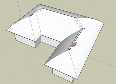
OVERVIEW FIG 4.1 Main building volume and roof profile in place.

OVERVIEW FIG 4.2 Stages in the creation of the basic roof, using the Follow Me tool, tracing the outline of the building plan.
Stage 2: Extruding the Roof Profile
With the Follow Me tool, extrude the profile using the outline of the building as your guide. Click on the profile, then, holding your left mouse button down, move your cursor toward the first edge of the outline, then follow the entire outline using the cursor until the entire extrusion is complete.
It looks a bit chaotic, but the hardest part is over.
Stage 3: Intersecting the Curved Roof Pitches
Now, you need to cut all the faces that are intersecting so that you can trim away the superfluous parts. The simplest way to do this is to select all the roof pitches, then right-click (Ctrl-click on a Mac) and choose Intersect > Intersect Selected from the contextual menu.

OVERVIEW FIG 4.3 Intersecting the roof curve with itself prior to cleanup.

OVERVIEW FIG 4.4 Deleting the superfluous faces and edges.
Stage 4: Cleaning Up the Unwanted Faces and Edges
This is the stage that can cost you quite a bit of time. Select all the faces that are definitely beyond the roof’s ridgeline and delete them by hitting the Delete key.
Attention
Make sure that you only select the elements you want to delete. For example, you can use the X-Ray display mode to make sure that you have not inadvertently selected any elements that you want to keep.
You can also use the Eraser tool to clean up the little “orphan” edges that remain. To keep the edge count of your model down, you can erase any edges between coplanar faces. If you need to, you can also erase any edges on the interior faces of the roof.
Tip
On a curved surface like this, you can display hidden geometry (from the Menu Bar, choose View > Hidden Geometry) to easily see any hidden lines dividing coplanar faces.
OVERVIEW FIG 4.5 Removing lines joining coplanar faces with the Erase tool.
Getting rid of all the little stray bits of edges that get left behind when you remove faces (“dust” as it is often known) can be a real chore. However, there is a plug-in to automate the task: cleanup_model.rb will automatically do the tidying up for you.
Creating a Gable End From the Roof Hip
If your building needs a gable end on one of the wings, you have two options open to you:
• Model your roof in parts, stopping every time that you encounter a gable end.
• Model the whole thing as a hipped roof and then edit it to create the gables.
Using the second method is usually the quickest.
1. Select the hip end (including the eaves) and move it so that the ridgeline projects beyond where you want your gable to be.
2. Move your selection so that the ends of the ridgeline are beyond where you want your gable to be.
3. Model a box that completely encompasses the hip end of the roof and place it so that one of its faces corresponds to the position of your gable (see Overview Figure 4.6).
4. Select the roof and the box, right-click (Ctrl-click on a Mac), and choose Select Intersected from the contextual menu. This will cut your roof where it intersects with the face of the box.

OVERVIEW FIG 4.6 Placing a rectangular volume for intersection.

OVERVIEW FIG 4.7 The roof volume cut using Intersect Selection.

OVERVIEW FIG 4.8 The gable end after removing the superfluous faces.
5. Erase the box and all the geometry that is beyond your gable line.
6. Draw a single line on the open end of your cut section. This will fill the open end.
And there you go. You can use this method with any sort of roof or building profile, even if it is curved.
Modeling Using Photos
Let us be clear on one thing: Modeling using photos in SketchUp is not the catch-all answer for every project or use. In order to create a model from one or more photos, you have to bear in mind several limitations:
• Some element in the photo must be at 90 degrees (i.e., perpendicular) to the horizontal elements, in order for SketchUp to be able to determine the perspective.
• You should aim for a three-quarter view of the whole object to be modeled, i.e., from about a 45-degree angle.
• You should not crop your photos because SketchUp needs the center of projection of the photograph to calculate the perspective.
• The resolution of the photograph should be sufficient to distinguish the details to be modeled.
• It is better to avoid photographs that have been taken with a wide-angle lens. These images contain distortions that make it impossible for SketchUp to calculate the perspective. You should also avoid telephoto lenses, since these images have only a shallow perspective.
• You should also avoid, where possible, objects in the foreground (vehicles, vegetation, furniture, people, etc.). These types of photo cannot be used for the application of textures, and the foreground objects can get in the way of modeling.
• The model to be created from the photo should have flat surfaces, more or less perpendicular to each other. PhotoMatch is not of much use if you want to model curved buildings.
Using the Match New Photo Tool
Even if the limitations of the PhotoMatch tool are numerous, its uses are equally so:
• Model an existing object (or one that has existed): furniture, decorative elements, design or historical objects.
• Model the surroundings of the project to evaluate its impact on the environment and vice-versa.
• Pull dimensions from a photograph when the area to be surveyed is inaccessible. The precision of any measurements will strongly depend upon the resolution of the photograph, the lens used, how carefully the axes are placed, and the unit scale set up in SketchUp.
Tip
Take note of the viewing angle and the focal length used while taking the photograph: This can help you greatly when integrating your model with photographs that have been edited in other programs.
PhotoMatch in Action
Stage 1: Taking and Retouching Your Photos
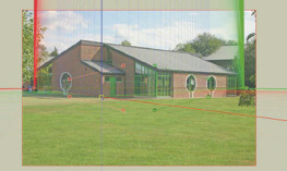
When taking a photo, you should always aim for a viewing angle of around 45 degrees. However, when there are a lot of trees around, this is not always possible. To reduce distortions as much as possible and to allow you to get the whole of your building in your viewfinder, choose a focal length of between 35 and 50 mm. Make sure that your camera is completely horizontal while you are taking the photos; a tripod with a spirit level is indispensable here. To get as much detail in your photo as possible, take it at the highest resolution that your device will allow.

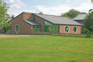
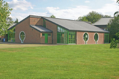
OVERVIEW FIG 4.9 Collection of photos showing building viewed from different angles.
The photos that you use are stored within the .skp file, and so using numerous images at very high resolution can significantly increase your file size and slow SketchUp down.
Tip
If you want to project the photo textures—apply the photo as textures on the surfaces of your 3D model—try and time your shooting session to avoid shadows. If the front of your building is generally obscured by vehicles or other objects, try to shoot on the weekend or holidays.
OVERVIEW FIG 4.10 Photo retouched to emphasize the horizontals.
When the photographs are available, you can rework them in an image editor like Photoshop. The idea is to limit as much as possible any tonal differences between the photographs you are going to use. This will avoid texture mismatches when you use the Project Textures command.
Tip
If you are not going to use your photographs to project textures, you can make your work in SketchUp easier by accentuating the horizontal elements of the building in your image editor, by using the Line tool in a contrasting color.
On the other hand, if you do want to use the photo to project textures, try and retouch them to get rid of any elements in the foreground and to correct any other problems (cables and wires, signboards, graffiti and dirt, etc.).
OVERVIEW FIG 4.11 The photo retouched to get rid of any elements that are in the way of the building.
Stage 2: Placing the Axes
From the Menu Bar, go to the Camera menu and choose Match New Photo. Choose your photo in the dialog box that appears and click on Open. SketchUp now displays the PhotoMatch workspace as well as your photo. SketchUp automatically creates a new scene with the name “name-of-your-photo (2D).” The Match Photo palette will appear at the top of your workspace.

OVERVIEW FIG 4.12 The PhotoMatch workspace.
First, move the point of origin (yellow square) so that it lines up with a prominent corner of the building that is visible on several photos. Now, take the handles on the red and green axes and line them up with horizontal elements in the building (in Overview Figure 4.14, they are lined up with the brick courses). To get more precision, you can always zoom in on your photograph in SketchUp.
OVERVIEW FIG 4.13 Placing the point of origin.

OVERVIEW FIG 4.14 Moving the axis handles onto the horizontals in the photograph.
Attention
The red axes absolutely must be perpendicular to the green axes. However, axes of the same color do not necessarily have to be in the same plane as each other in the photo; they do have to be parallel, though.
Tip
Avoid using the ground plane as a reference; generally, it is never horizontal.
Once the origin and the four axes (2 red, 2 green) have been placed, they are now, theoretically, correctly oriented according to your photograph. You can now scale your model by clicking on one of the axes and holding down the left mouse button. Two arrows appear on the selected axis, and by moving the mouse, you can change the scale to make it correspond to the photo. Once that has been achieved, click on the Done button, and you can start to model.
Tip
It is difficult to get the right scale unless you have already set up a reference point. But there is no need to panic: You can set the scale of your model once you have created an element whose dimensions you know. This could, for example, be a door or window opening that you measure on-site. Then, use the Tape Measure tool, as previously explained, to scale the whole model.
After clicking the Done button, you will leave PhotoMatch mode. If you need to make any modifications, right-click (Ctrl-click on a Mac) on your PhotoMatch Scene tab and choose Edit Matched Photo.
Stage 3: Modeling
Finally, you can model your building or object using all of SketchUp’s classic drawing tools. It is essential to begin your modeling at the axes origin. In Overview Figure 4.15, modeling was begun by drawing a rectangle on one of the facades and extruding it along the length of the building.
Tip
If you use the Orbit tool to change your point of view onto the model, the display of the photograph will disappear. To get it back, simply click on the PhotoMatch Scene tab.
Stage 4: Project Your Textures
Once the face is created, you can texture it using the photo. Select one or more faces and click on the Project textures from photo button.

OVERVIEW FIG 4.15 Modeling in Sketch Over mode.

OVERVIEW FIG 4.16 Projecting the textures onto the modeled faces.
Stage 5: Using Other Photographs
If you have any other photos of the building or object being modeled, you can add them simply by following the same steps in stages 1–4. This way, you can model your object or building in its entirety.

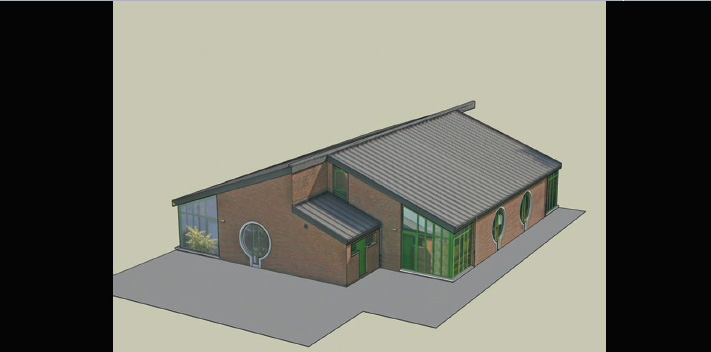
OVERVIEW FIG 4.17 Use another photo to carry on modeling the other sides of the building.

OVERVIEW FIG 4.18 The final building model, the result of using several different photos.