
Chapter 8

SketchUp for Woodworking
After retiring from a 36-year career in the engineering and construction industry (which involved locations in Maryland, California, London, and Baghdad), Tim Killen pursued a lifelong interest in woodworking. He is particularly interested in reproducing eighteenth century museum pieces, and his home is already filled with dozens of furniture reproductions in mahogany, maple, cherry, and pine.
Tim has written several articles on furniture making in Woodwork Magazine and Fine Woodworking. He is a contributing editor to http://www.finewoodworking.com/ and is involved in developing and producing the blog Design. Click. Build. (http://www.finewoodworking.com/blog/design-click-build) on SketchUp. He also teaches classic woodworking and SketchUp at a local adult education center.
Tim Killen is a graduate electrical engineer from Purdue University, Indiana. He also has an MBA degree from Golden Gate University, San Francisco. He lives in Orinda, California, and his email address is [email protected].
Project: Reproducing an eighteenth-century mahogany bookcase.
Tools: SketchUp and Layout.
I enjoy reproducing classic eighteenth-century furniture and museum pieces; however, drawings for these pieces are usually not available. Therefore, I face the challenge of producing detailed design from scant information available in books, and sometimes from only pictures and overall dimensions.
In the case of the mahogany bookcase, I found a front and side orthogonal view with overall dimensions in a book by Charles H. Hayward called Period Furniture Designs. The only dimensions were overall width, height, and depth; but these are all I need to produce a complete and detailed three-dimensional (3D) model in SketchUp.
SketchUp is an extremely valuable tool for me in breaking down difficult projects and enabling my construction in the shop. It is so valuable that I will not start a construction without first building the project in SketchUp. The shop work is facilitated by the integrity of the design and the detailed products of the model, that is, fully dimensioned details, joint information, X-ray views, and full-size templates. I save time and materials, and more importantly, eliminate rework and frustration with SketchUp.
In many cases, including this bookcase, I attempt woodworking processes never before performed by me. I like these challenges but would not have had the confidence to attempt them without SketchUp. SketchUp has a way of uncovering and exposing the details and breaking down complexity, so that the actual work is understandable and doable.
The following picture is produced from the SketchUp design file. I used SketchUp to texture the model with mahogany wood grains based on the actual finish applied by me to the bookcase. One of the most challenging components of a bookcase is the cornice. This is also shown in the figure.
Project Context
The only software used in this project is SketchUp Pro, which includes Layout. All the design modeling could have been done with the free version of SketchUp. I use Layout to produce professional drawing packages in portable document format (PDF) for my students and other customers.
Technical Aspects
Prior to using SketchUp, I used various two-dimensional (2D) computer-aided design (CAD) systems to develop design drawings. I was familiar with 3D CAD, which was extensively used for developing large-scale process plant design at my work prior to retirement. I wanted 3D capability in my woodworking hobby at the time, but found these large CAD systems very expensive and difficult to use. I wanted 3D capability so that I could create unlimited views of the project in any direction or angle. Also, I would be able to produce exploded views, and visualize all the pieces of the furniture and how they connect. The 3D model would give me the opportunity to check joint fit-up and integrity.
About 4 years ago, I found SketchUp to be the answer to my 3D interests, and since then I have not used any other system or reverted to 2D systems.
In this case of designing the mahogany bookcase, I scanned the orthogonal front and side views in the book and imported the images in JPG format into SketchUp. After scaling-up the images in SketchUp to full size, I began to trace over the components of the bookcase, including stiles, rails, muntins, doors, and moldings. With these initial traces, I was able to reconstruct each 3D component, add the joint details, and fit these parts into a whole assembly.
Tip
When importing images (File/Import), SketchUp offers three alternatives: Use as image, Use as texture, or Use as new matched photo. Most of my imports, including the ones for this case, use the first option Use as image. This is the applicable option when importing orthographic views to be used as a background for tracing over.
After importing, straighten the image to align with the red and blue axes. This is done by drawing a line on top of a long horizontal or vertical line in the image. With the image selected, pick the Rotate tool and click the mouse to place the protractor on the end of the line. Click on the image (at a point of desired alignment with the placed line) and rotate the picture until it snaps and aligns with the placed line.
Also, the image needs to be set at full scale. Draw a line at a precise length on a part of the image for which the dimensions are known. Using the Tape measure tool, it is important to check the actual length of the object of known dimension in the image. Calculate the ratio of lengths (placed line length vs. object image length). Pick the Scale tool and adjust the size of the picture by typing in this ratio. Now, the objects in the picture will measure properly to their actual dimensions.
In furniture design, I find the following SketchUp features to be the most useful:
Components (every piece of the furniture is defined as a SketchUp component)
Move/Copy tool (used to precisely connect and copy components)
Line tool (used to create the lumber pieces)
Arc tool (for making shapes and moldings)
Push/Pull tool (gives a face of lumber its thickness)
Tape measure tool for temporary guidelines (particularly useful in designing detail complex joints)
Flip-Along (used to mirror various component parts, e.g., legs of a table) Dimension tool (to add measurement annotations).
Scenes (for saving views of the model that create the final documentation package)
Intersect (used to join odd-shaped or curved pieces or to make cabriole legs) Follow Me tool (creates turnings and molding shapes along a path)
Step 1: Designing the Complex Gothic-Style Cornice Molding for the Bookcase
Goals: To determine all the components required to assemble the molding and define how these pieces fit together.
Inputs: The limited orthographic front and side views provided in the reference book.
Tool: Only SketchUp.
The beauty and complexity of this cornice is one of the reasons I wanted to build this piece. I had not built a construction like this previously, and was curious and motivated to try it. My first step was to reproduce the molding shape by tracing over the scanned image. I used a combination of the line and arc tools to trace over the image. Multiple connected arcs were required to match the shapes. SketchUp conveniently tells you when the connected arc is tangent to the previous arc by turning a cyan color. Connecting the right shapes together is sometimes an iterative trial-and-error process.
The first step in recreating this cornice is to make a profile face of the molding shape. The image in Figure 8.1 shows the results of this first step.

FIG 8.1 Profile face of the molding shape.
In creating this profile, I also divided the face into sections that represent individual component parts of the cornice. These parts or layers (totally seven in number) can now be extruded (minus the pendants) into solid lumber components with the Push/Pull tool, as shown in Figure 8.2.
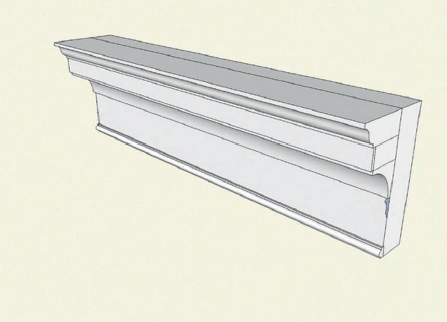
FIG 8.2 Extruded components.
I continued to add detail to the cornice by defining the turned pendants as shown in Figures 8.3 and 8.4. The turned pendants were created in SketchUp using the Follow Me tool. A pendant-shaped half face was created by the trace-over process. A semicircular path was created with the axis at the origin of the circle. I rotated the circular path 7.5° so that the midpoints of the circle segments are aligned with the red axis. This ensures a clean Follow Me with a quality flat face on the half-pendant. Since the pendant is so small, the pendant shape and circular path should be scaled-up by a factor of 100 (SketchUp does not handle small faces well). After selecting the circular path, pick the Follow Me tool and click on the pendant shape. Figures 8.3 and 8.4 show the steps in making pendants.
The arched and hollowed-out cove was created by making a shaped block and then using the Intersect capability on the cove molding. An arch cut-out tool was created using the Push/Pull tool with the face of the arch shape as shown in Figure 8.5.
Place multiple copies of the cut-out tool spaced accurately into the solid cove molding as shown in Figure 8.6.
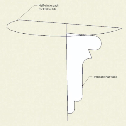
FIG 8.3 Preparation of pendant to use with Follow Me tool.

FIG 8.4 Half-pendant results of Follow Me.

FIG 8.5 Create the arch.

FIG 8.6 Preparation for intersecting the cove with cut-out tools.
Explode all components (Cove molding and Cut-out tools); select all, right-click on the selection, and choose the option Intersect Selected from the pop-up menu. Use the Eraser tool to clean up the waste, and see the results as shown in Figure 8.7.
Now, we are ready to assemble all the components into the completed cornice assembly as shown in Figure 8.8.

FIG 8.7 The cove molding after intersection.
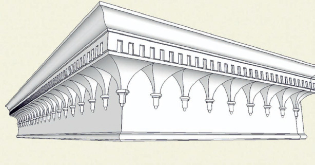
FIG 8.8 Assembled cornice.
After creating the completely assembled cornice, I began developing the drawing documentation with SketchUp to enable the actual construction in the shop. This includes an exploded view and detailed views of each cornice part. Each view of the cornice was saved to a Scene. I could easily return to each view by clicking on the Scene tab, and print the page to take to the shop.
I also saved Scenes for full-size templates. With the camera set to “parallel projection” mode and a standard view such as front view, right side, or top view, I was able to print full-scale sheets to produce templates for marking out the lumber in the shop.

FIG 8.9 Exploded view.
Tip
The following steps are to be followed when printing full-sized templates:
1. Make sure your camera is in parallel projection, as you cannot print a full-size template in “perspective” mode.
2. You should have your camera view in one of the following standard views:
(a) Top
(b) Front
(c) Right
(d) Back
(e) Left
3. I set up a toolbar with the camera standard views so that I can quickly set this option.
4. In this case, I do not click on the Print icon; rather, I clicked on File/Print Preview. I find that I need to adjust the view to get the least amount of tiled pages. This is an iterative process, so the Print Preview avoids wasting paper and ink.
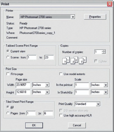
5. After I click on Print Preview, the following dialog box pops up:

6. I check Properties of the dialog box to set the paper to Portrait or Landscape options.
7. The “fit to page” option is unchecked.
8. The Scale is set so that it is 1 in the printout, and 1 in SketchUp.
9. I look at the tiled sheet print range and note the number of pages that it will take to fully print the full-size template. In this case, it will take six pages.
10. I click the OK button, and the following view of the template will appear:
11. Note that I have a two-page view of the template, which is an option that I like, by clicking on one of the tabs in the view shown here.
12. By scrolling through all six pages, I see that I have to print only four pages to get all that I need.
13. If I like this arrangement, I can click on Print in the upper left-hand corner, or I can click on the Close button and return to SketchUp to rearrange the view on the screen (using Pan and Zoom). No orbiting is performed in this step, since you have to maintain a standard camera view. This is an iterative process of going back and forth to try out the Print Preview. You can also try a Portrait view to see if this reduces the number of pages.
14. When I click Print on this Preview, I get the dialog box again.
15. In this specific case, I know that I only need to print pages in the print range 1 – 4, so I change the number 6 to 4 and click the OK button.

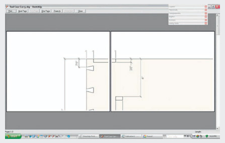
FIG 8.10 Cove full-size template.
Step 2: Building the Lower Carcase
Goal: To produce the detailed design of the lower carcase including dovetail joints.
Inputs: Overall front and side views provided in the reference book. Tool: SketchUp.
After completing the design of the cornice, my next step was to develop details for the lower carcase. Again I used the scanned images from the book to obtain the width, depth, and height of the lower carcase. I started the SketchUp model from the sides, adding the top, bottom, and finally the shelf. The initial modeling is done without joinery, and thus focuses on component creation and carcase sizing. When I was finally satisfied with the overall structure, sizing, and proportion, I detailed the joints including dovetails. The dovetails are first defined on the top piece, then with the top properly positioned on the side, and finally pins are created on the side component.
Step 3: Creating the Lower Cupboard Doors
Goal: To produce the detailed design of the lower cupboard doors including all mortise and tenon joints.
Inputs: Overall front and side views provided in the reference book. Tool: SketchUp.
The lower cupboard doors are more complicated than they seem. There is a solid, flat panel with separate corner pieces and an applied bead covering the joint between the panel and the other door components, the stiles and rails. In SketchUp, I worked on various alternatives to accommodate expansion/contraction of the center panel. I settled on having the corner pieces with tongues glued into grooves in the stiles and rails. Then I allowed an expansion gap surrounding the perimeter of the panel. The final SketchUp design of the door is shown in Figure 8.12 in an exploded view.

FIG 8.11 Carcase construction.

FIG 8.12 Lower cupboard door.
Step 4: Creating the Upper Muntined Doors
Goal: To produce the detailed design of the upper muntined doors including the angled muntins and accommodating the glass inserts.
Inputs: Overall front and side views provided in the reference book.
Tool: SketchUp.
Upper muntined doors comprise standard eighteenth-century-configured stiles and rails. These are connected through tenons. Also, a 3/16″ bead is milled into the inner edges of stiles and rails. These beads are mitered at the corners. I started designing the SketchUp model with the construction of the stiles and rails as shown in the following illustrations (Figures 8.13, 8.14). The beads are created in SketchUp using the Push/Pull tool, and the miters are made by introducing an oversized surface plane at a 45° angle at the location of the miter joint. Then, using the Intersection with Model feature, the bead is cut with a miter joint.

FIG 8.13 Door rail.

FIG 8.14 Door stiles.
The upper door stile is designed with mortises for connecting the rails. After outlining with the Line tool, the mortises are created with the Push/Pull tool. The stile also has the mitered bead on the inside edge and fits the mitered bead on the rails.
After completing the SketchUp model of stiles and rails, I moved on to the muntins. I extruded a muntin shape using the Push/Pull tool. Then I worked on the method of connecting muntins to the rails and stiles. The result is shown in Figure 8.15, in which the muntin end is fitted with a small tenon that fits into 1/8"-wide slots in the stiles and rails. Also, the bead end of the muntin is mitered to a socket into a V-shaped cut at the edge bead of the stiles and rails. These V-shaped cuts again required placement of an oversized rectangular face on 45°; then using the tool Intersect with Model, the V-shaped notches are cut. You can see this connection in Figure 8.15.
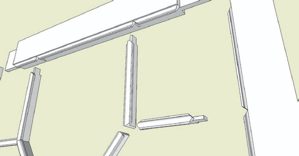
FIG 8.15 Muntin connections.
Again I used SketchUp’s capability to produce orthographic and cross-sectional views to help with the construction of muntin shapes. Figure 8.16 gives an illustration and a full-sized template that I used in the shop.
After working out the muntin connections at the stiles and rails, I began to develop the muntin-to-muntin angled intersections. After positioning (in SketchUp) the muntin pieces into their respective places in the array, I made the precise angled cuts on these muntin pieces at their intersections. See the following close-up illustration (Figure 8.17) of one of these muntin intersections. Again, I made the angled cuts on the end of the muntin pieces by placing a rectangular plane at the intersection and using the Intersection with Model tool. It is very helpful when SketchUp provides these various angle measurements (as no further geometric calculations necessary) using the Protractor tool.
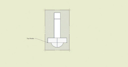
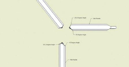
FIG 8.17 Angled muntin-to-muntin connections.
Conclusion
Increasingly, woodworkers around the world are adopting SketchUp as a design tool. This application opens up new 3D capabilities that were previously unavailable, except to a few professional CAD designers and illustrators with esoteric, hard-to-use, expensive systems. Now, woodworkers can “build” and assemble their furniture on the computer (prior to real construction in the shop) using SketchUp’s components representing each separate lumber piece. The joint details are also developed in the furniture model, and these details can be easily viewed and checked with SketchUp’s unlimited viewing options. Exploded views, which are so helpful for illustrating the piece-by-piece assembly and simplifying the construction, are now easy to create.
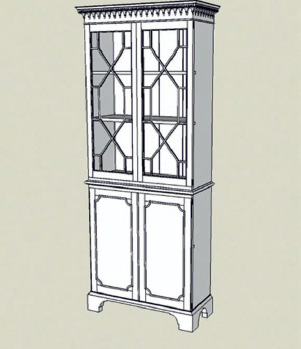
FIG 8.18 Final, complete SketchUp model.

FIG 8.19 The constructed reproduction in mahogany.
When you design in SketchUp, you are “fabricating” and connecting furniture parts, not simply drawing lines and arcs. You are in 3D space and using the components you create for a close correspondence between shop work and the computer design process.
The basic design strategy is the same irrespective of whether you design from scratch; work from a picture, a rough sketch, or a detailed-scale drawing; or take measurements from an actual piece. The different levels of detail in these sources affect the ease of design in SketchUp, but they do not necessarily change the basic approach. Begin at the foundation and work your way upward, adding details as you go. Think in terms of the procedure you would use in the shop to construct this piece of furniture. Which parts would you build first? How would you sequence the construction? Working in SketchUp is startlingly similar.
Even when I have access to detailed drawings, I find it beneficial to build a SketchUp model. Too often, drawings are incomplete and full of errors. I save time, frustration, and materials in the shop if I construct a SketchUp model first. As a by-product, SketchUp provides full-sized templates that I can use to lay out joints or specific shapes. Working in SketchUp also gives you time to preview the actual construction steps as you build the model. You get a good picture of how to make parts and fit them together.