
OVERVIEW 1

Working on Complex Models in SketchUp
SketchUp is both simple and intuitive; there is no doubt about that. It usually takes a couple of hours to get grips on it and to create your first 3D models. But when you are using it for a professional project – with all the attendant time and quality constraints – you have to get a few things straight first to avoid the traps that users inevitably fall into, whether they are beginners or experienced operators.
When you are working on a complex project, made up of a large number of elements, SketchUp can slow down, often considerably. The working methods and the tips and tricks presented in this book can considerably improve SketchUp’s performance, enabling you to work much more quickly. The good news is that many of the methods used to efficiently organize a model actually make SketchUp a lot quicker.
So, here are a series of good habits that you should pick up when you are working with your models, in order to optimize SketchUp’s performance.
Configure SketchUp
In an architectural project, solid foundations are indispensable for supporting the rest of the construction. Here is how to go about creating solid foundations in SketchUp.
Configure Your Template File
At the start of the project, configuring your model is a fundamental step that you should not neglect. But who gets any pleasure from continually reinventing the wheel? Instead of configuring your model for every new file, create your own template file in which you have configured all the options that do not change between projects.
To save your template file, from the Menu Bar, choose File > Save As Template…. Type any relevant information into the fields (file name, description) and click Save. If you have a version of SketchUp earlier than 7.1, choose File > Save As…; in the dialog box that appears, save the template file in the path C:Program FilesGoogleGoogle SketchUpResourcesen-USTemplates in case of Windows and in the path ~/Library/Application Support/SketchUp/Templates (where “~” is the name of your home directory) in case of Mac.
If you are using the Save As… method, type the name of your template file in the File Name field, click on Type, select SketchUp Model, and then click on Save. Using both these methods, your template file will appear in the list of templates that are available when you click on File > Preferences… > Template. You can then create different template files and select them according to the type of project that you are working on.
Before you save, here are several options that you will need to set.
Choose Your Units
Do you want to work in a fluid and an efficient manner with the others taking part in your project? And, additionally, do you want to take advantage of the vast library of SketchUp components available through the Google 3D Warehouse without having to rescale them? In that case, start by setting the units of measurement of your model. To do this, click on the Window menu and choose Model Info. In the dialog box that appears, select Units from the left-hand column and choose the units that you will be working with in your model. You also have the option at this point of specifying the precision of the units of length and angle.
Info
SketchUp does not handle multiple decimal places very well. If you are working on an object at very small scale, you should choose a more appropriate smaller unit that will allow you to work with whole numbers.
Creating the Layers That You Will Use the Most
If, in your work, you regularly use the same layers, creating them in the template file means that you will not have to re-create them all over again for each new project. To add new layers, go to the Window menu and call up the Layers palette. Click on the Plus icon to add a new layer, making sure you put a meaningful name in the name field.

OVERVIEW FIG 1.1 Adding a layer.
Tip
Many practices have standard naming conventions for layers used in models across all the programs that are used in the office (31 Windows, 47 Door Furniture, etc.). Manually entering the name of a layer each time that you need it is tiresome and a potential source of errors. Furthermore, you do not want to overload your Layers palette by systematically adding all the types of layers used by your office in your template file. To automate the creation of layers, guaranteeing the correct name, follow these instructions:
• Create a library of external components, called, for example, “Layers,” that will contain one file for each layer name used by your practice.
• In a model, erase all the unused layers (except Layer0).
• Create a layer using your layer-naming system.
• Draw an object – a rectangle, for example – and make it a component, giving it the same name as the layer that you have just created.
• Save this model into the Layers Components library that you previously created.
• Repeat the operation for any other layers.
Once you have carried out this procedure (admittedly long, but you only have to do it once), you simply have to insert the component corresponding to the desired layer in order to automatically create that layer. The layer will then have exactly the same name as the component. Then, simply delete the component.
Purge Any Unneeded Elements from Your File
For example, you should erase the figure that appears each time you create a new file from your template file. Alternatively, you could erase the figure in the original template file as well. Make sure that your file does not contain any components or layers that you will not need.
Tip
To automatically delete unneeded elements, click on the Details icon in the Layers, Components, Materials, or Styles palette and select the “Purge” command.
The PurgeAll.rb plug-in, created by TIG, allows you to automate the purging of your model while allowing the possibility of selecting the types of elements that you want to purge.
Set Up Keyboard Shortcuts for Your Most-Used Tools
Whatever the software, keyboard shortcuts save you a lot of time and increase your productivity. SketchUp is no exception to this rule.
To see the default keyboard shortcuts, go to Window > Preferences > Shortcuts (Windows) or SketchUp > Preferences… > Shortcuts (Mac). Or, you can use the old Quick Reference Card (no longer available under the Help menu, but you can download at http://goo.gl/FR0a).
Tip
It is up to you to change the default shortcuts, but first make sure that you are the only person working on this installation of SketchUp: Your colleagues will not be pleased if all their keyboard shortcuts have been changed.
Organize the User Interface
Organize your installation of SketchUp to give priority to your Workspace. Try and avoid the clutter of toolbars and palettes that can get in the way of your model. Give priority to palettes anchored at the side of your Workspace, laid out according to the proportions of your screen.

OVERVIEW FIG 1.2 Stacking the palettes.
For the palettes, you can save a lot of time and space by displaying only the title bar on each palette. You simply need to click on the title bar to expand or collapse the palette. You can also think about “gluing” title bars together (they are “sticky” and will snap to one another); in this way, you can move all the palettes around, simply by grabbing the title bar of one of them. Practical and quick.
Other Things to Configure
• Scenes
• Rendering style
• Face and edge style
• Font and size used for text labels
• etc.
This wraps it up for the configuration of your template file. Other parameters can be changed on a case-by-case basis, such as the following:
Model Location and Setting the North Point
For the ultimate in realism, make sure that you set the geographical location of your site by clicking on Window > Model info > Location and entering the geographical coordinates of the site.
You can also configure the direction of the north point for your project. You can either type in an exact angle or indicate the orientation manually by clicking the Select button. Click on a point in your model, for example, at the center of the north indicator of an imported plan, and then click on a second point to indicate the north direction. By selecting Show in Model checkbox, you can visualize the north angle directly in your Workspace.
Once these two parameters are set, shadows in your model will be correct.

OVERVIEW FIG 1.3 Setting the geographical location and orientation of the project.
Creating with SketchUp
A lot of the problems that SketchUp users encounter are caused by inappropriate working methods. Here are some rules for best practice:
Save Your File
The first thing that you should do, before you even draw a single line, is to save your new file with a meaningful name. This means that your automatically saved backup files will be in the same folder as your .skp file. Your file must be saved at least once for this to work.
Model at or near the Center of the X, Y, and Z Coordinates
SketchUp has difficulty in displaying a model that is far removed from the origin of the X, Y, and Z axes. In this situation, you can get rendering errors while using the Orbit tool O (or click on the middle mouse button).
As far as possible, model at or near the origin of the axes.
Tip
If your model looks truncated (parts of it disappear intermittently) from certain viewing angles and it is a long way from the origin of the axes, start by deleting elements that are a long way off from your model. If the problem persists, select the model and move it closer to the origin of the axes.
Always Model on Layer0
Difficulties with using layers correctly often lie at the heart of many problems that SketchUp users face. Users often find that objects remain visible even though the layer is switched off or, conversely, objects disappear even though the layer that they are on is switched on. It can get really confusing!
Info
You need to know that SketchUp does not use layers in the same way the other CAD programs do. In SketchUp, the layers do not isolate objects; they simply control their visibility. It is essential that all edges and faces be created on Layer0. Only groups and components should be assigned to other layers.
Model by Following the Red, Green, and Blue Axes
Generally, if you model off the X, Y, or Z axes or you do not use inferences, you can never be sure of the (often surprising) results that you will obtain. By default, SketchUp starts out drawing on the ground plane (level 0), but things can get out of hand when you venture into the third dimension. This is why it is always better to follow the Red, Green, and Blue axes because these will help you place your design in 3D space. Of course, you will often want to work off axis, so this is what you do…
Change the Axis Orientation When Drawing Off-Axis Objects
If you have to model a project where an important part does not line up with the main X, Y, and Z axes, you can always realign the orientation of the axes using the Axes tool. Click on a point to set the origin, then on a second to define the X axis and a third to define the Y axis.
To go back to the default setup, click on the axes’ origin with the right mouse button (Ctrl-click on a Mac) and choose Reset.
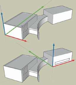
OVERVIEW FIG 1.4 Changing the axes.
Tip
If an object is located exactly on this intersection, click as close to the point as possible in an area of your model that does not contain any objects. If there are objects all around the axes’ origin, the easiest solution is to simply hide them and repeat the operation.
Tip
A particular orientation of the axes can be saved by creating a scene and making sure that the Axes Location check box is ticked. You can also save a scene before you change the axis orientation, which will enable you to return to the default setup with a single click.
Use Construction Lines
Construction lines are the best ways for modeling precisely in SketchUp. There are several methods available for creating construction lines:
• Use the Tape Measure tool. Click on two points of one edge to define the direction of the construction line.
• Use the Protractor tool. Click on a point to set the origin or rotation and then on the second point to define the axis of origin. You can then click on the new point or enter a value for the angle of rotation for the construction line.
Using Inferences
You must be a past master at using inferences, by now. No? Inferences correspond to the well-known snapping functions in other CAD software, like AutoCAD or Vectorworks. In SketchUp, these drawing aids are always switched on.
When you are drawing or modifying an object, inferences provide you with a visual aid in the form of the color of the “snap dot” displayed with the particular inference. These come in two types:
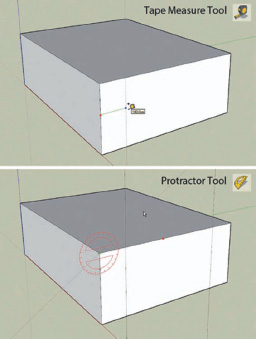
OVERVIEW FIG 1.5 Creating construction lines to assist in making your model.
Point Inferences
Endpoint: Green dot
Midpoint: Light blue dot
Intersection: Black dot
On an edge: Red dot
At the center of a circle or a circle segment: Green dot (SketchUp 6) or dark blue dot (SketchUp 7)
On a face: Dark blue dot
Linear Inferences
On an orthogonal axis: A dotted help line, the same color as the axis, will appear when you are drawing or moving an object along this axis.
In relation to a point: A dotted line will appear between the cursor and the point in question.
Perpendicular: You can tell SketchUp which line you want to draw perpendicular to by moving your cursor over the edge (without clicking). A magenta line indicates that the line that you are following is perpendicular to this edge.
Parallel: You can use the same method described earlier to draw lines that are parallel to one another. Simply hover your cursor over the line parallel to the direction that you want to follow.
Tangent: This inference is extremely useful for drawing segments of circles that are tangent to other arcs or lines. Start by clicking on a point on the line or the arc in question and then click to select the end point of the arc. As you are moving the cursor to set the radius of curvature of the arc, the arc will turn cyan (light blue) when it is tangent to any lines impinging upon it.
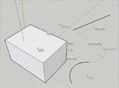
OVERVIEW FIG 1.6 Point and linear inferences.
Tip
In order to make sure that you are drawing or moving an object along a specific axis, you can lock the inference along that axis. As soon as you see the dotted help line appear with the color of the axis that you want, hit the Shift key and keep it held down until you click the second point. When the inference along an axis is locked, the help line appears thicker. You can also lock axes by using the cursor keys on your keyboard: Hitting the “up arrow” or “down arrow” keys will lock movement or drawing in the Blue axis; hitting the “right arrow” key will lock the Red axis; and hitting the “left arrow” key will lock the Green axis.
Tip
SketchUp can sometimes be a little picky when activating an inference; at other times, there can be so many inferences to choose from that the program can not decide which one to choose. If this happens, you can help out by repeatedly mousing over the point or edge that you want to indicate to SketchUp that you want to activate the inference about that point or edge.
Tip
You can also easily combine inferences. You can, for example, draw one line parallel to another (by mousing over the line beforehand), lock the axis (by holding down the Shift key), and click on a point (using the End Point inference) to set the length of your line.
Model Only at the Level of Detail Sufficient to Carry Out Your Project
The more faces and edges in your model, the harder SketchUp and your graphic card will have to work to refresh the images on your screen. To take the load off your processor and to keep the rendering flow smoothly, limit the complexity of your model as much as possible. For example, if an object is in the background, you could use a texture to simulate faces modeled in three dimensions.
Reducing the Number of Segments in Curves
Arcs and circles are composed of a set number of straight segments (12 and 24, respectively, by default). This number of segments can be reduced according to the object size, its proximity to the camera, and the final use to which the project will be put. For example, for a really stretched-out arc or an element at a distance, you can reduce the number of segments to six or eight. This reduction in number of segments can have repercussions later in the number of faces produced when a surface is extruded with the Push–Pull tool or with the Follow Me tool.

OVERVIEW FIG 1.7 Reducing the number of segments in a curve.
Info
If you are making a model that will ultimately be used to produce photoreal renders, you may have to actually increase the number of segments in order to get smoother curves and surfaces.
Do Not Get Ahead of Yourself by Modeling Too Many Details, Too Soon
It can sometimes be tempting to add details in the very first conceptual stages on a project. However, the more detailed the model is, the more time the subsequent modifications will take. It is better to go forward step by step, limiting the complexity of the model to only that necessary for the current task in hand. Check every stage in your modeling before proceeding further and adding details.
Tip
Even if you do take these precautions, you sometimes still have to take a step backwards, returning to an earlier version of your model. Get into the habit of systematically saving each modeling stage with a unique file name. In this way, you can get back to an earlier stage should the need arise.
Use Low-Resolution Images
Using images in your model can considerably slow down SketchUp’s real-time rendering. This is particularly noticeable with large-scale (high-resolution) images that have been imported or applied as textures. If possible, use reduced-size images. You can easily reduce the resolution of an image with software like Photoshop or the various image conversion software like XnView, IrfanView, or Picasa™, for example.
Finding Your Way Around in SketchUp
Navigating your way around in a complex 3D project can sometimes be difficult. The Red, Green, and Blue axes are a useful visual aid, but they will always arrive at a moment where you get hopelessly lost.
Position and Set Up the Camera
One of the first things you need to do to make working inside a 3D model easier is to position the camera using (logically) the Position Camera tool. You can then set the eye height from its default 5’6” (about the average eye height in adults) by typing in a new value in the Value Control Box on the far right of the status bar at the bottom of the Workspace window.
Once the camera is placed in a good spot, you can change the angle of view by clicking on the Look Around tool. At this stage, you can still change the eye height.
You can then use the Walk Through tool to move around your model in three dimensions, using either your mouse or the cursor keys on your keyboard.
The Position Camera tool is a great help, but there are also other tools that can help you avoid selecting hidden edges or faces (and I am sure you can guess what the consequences of that are) or that can help you to orient yourself when the camera height is too low.
Changing the Face Styles
The Wireframe face style allows you to see whether you have accidentally selected any hidden edges or faces. If you have done this, then simply moving the visible selection can have catastrophic results at other places in the model.
Tip
As long as you have not closed the file, you can always get out of the above situation by using the Undo command Ctrl+Z, assuming that you have noticed it in time.
Change to Wireframe mode to see if you have accidentally selected hidden faces or edges.

OVERVIEW FIG 1.8 Selection with shaded face style.
OVERVIEW FIG 1.9 In wireframe mode, you can see that you have accidentally selected hidden faces.
A more practical solution is to change to X-Ray mode. This allows you to check for any unintended selections, but because it renders the faces as translucent, it makes it easier for you to orient yourself within your model. It also preserves depth perception, something that practically disappears when in Wireframe mode, especially if you have perspective switched off.

OVERVIEW FIG 1.10 X-Ray mode.
Tip
You should always aim to lock groups and components that you know will not be erased or moved, for example, plans imported from other CAD programs. Select the items that you want to lock, right-click (Ctrl-click on a Mac), and choose Lock from the contextual menu.
Displaying Your Model Using Sections
For developing or presenting the interior of a SketchUp model, the Section Plane tool is particularly useful. You can, for example, create a horizontal section plane for each story and front-to-back and side-to-side section planes that you can then switch on and move around according to your wishes. Do you need to work on the ceiling of a room? Activate a horizontal section plane and select the Reverse option. You can now change your camera position to get the best possible view onto your ceiling.
Tip
If you have the Section Planes option ticked in your Scenes palette, you can combine section planes with scenes, enabling you to turn a section plane on or off with a single click, simply by choosing the appropriate scene.

OVERVIEW FIG 1.11 Using sections.
Zoom Extents for an Overview of Your Project
Are you lost? Can’t you orient yourself inside your 3D model? If this happens, it is time to turn to SketchUp’s life preserver: The Zoom Extents tool. Zoom Extents will zoom the current view so that your entire model fits within the work space.
Organize Your Project
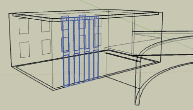
Managing Imported Objects
Let’s not kid ourselves; files that you import from other CAD programs will more than likely cause problems once they are in SketchUp, for example, overlapping lines, unwanted bits and pieces that bog down your model that is composed of too few segments, objects not recognized by SketchUp, etc. There are many good reasons for trying to avoid modeling with imported objects.
The first thing that you should do is to select any imported elements, group them, and then lock the group (its bounding box will turn red). Then create a new layer to which you will assign this group. Done! This group cannot interfere with the rest of your model now.
Then you can use this group and its End Point inferences to trace the objects that you want to model. It does take a little time, but you will avoid a lot of frustrations down the line.

OVERVIEW FIG 1.12 Lock groups created from imported objects.
Edges and Faces in SketchUp
In SketchUp, edges are distinct from the faces they define. When the end points of three or more coplanar edges touch, a face is created. If you now select the face and erase it, the edges will remain exactly where they were. Conversely, if you erase one of the bounding edges, the face is automatically erased. As soon as you move an edge or a face, any entities touching it will also be displaced by the same amount. This is a consequence of SketchUp’s “sticky geometry.”
This “stickiness” can come in useful for certain types of modeling operation, but often you will be able to “unstick” various elements so that you can move them without affecting the rest of the model. Here is how you do that.
Using Groups and Components
Knowing how to use components properly is the cornerstone of efficient SketchUp use. Furthermore, I would suggest that you adopt Tim Danaher’s motto: “group early, group often.” You should group elements when you want to disassociate them from the rest of the model without affecting it or when you want to select multiple elements with a single click. Apart from their use for “unsticking” geometry, groups are also indispensable if you want to use the Layers palette – or better still, the Outliner – efficiently.
When to Group and When to Make a Component?
If you are going to use a collection of elements only once, make a group. In all other cases, make a component.
Tip
SketchUp has one feature that on its own means that you should be creating components rather than groups: In the Menu Bar, go to View > Component Edit > Hide Rest of Model. When you choose this option, the rest of the model is automatically hidden when you enter a component to edit it. If you choose the other option, Hide Similar Components, all the instances of the edited component will be hidden.
This option is saved at the same time as your file. You could, therefore, add this option to your template file so that you can benefit from it automatically.
Making a Group
To create a group, select all the elements that you want to collect together or isolate, right-click (Ctrl-click on a Mac), and choose Make Group from the contextual menu. Your new group will be displayed with a blue bounding box.
Tip
By default, all new groups are given the name… Group. This means it can be difficult to keep a track of what is in your model, so get into the good habit of giving your groups meaningful names, in the Entity Info pallette or in the Outliner. Using the Outliner, you can select your name groups extremely rapidly.
Making a Component
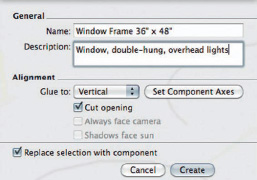
To make a component, select all the elements you want to collect together or isolate, right-click (Ctrl-click on a Mac), and choose Make Component from the contextual menu. In the Make Component dialog box, you will be presented with many options. In order to make group work easier, you can add a description of the component here.
In the Alignment field, you can choose a particular type from the drop-down menu:
• None. If you choose this option, your component will not stick to any particular surface: You can move it freely with no constraints.
• Any. Your component will stick to any face in your model. This is the most practical alignment mode. The only constraint is that the component must be inserted either on a face or on the ground plane.
OVERVIEW FIG 1.13 Making a component.
• Horizontal. Your component will only stick to horizontal faces. This can be useful, for example, to ensure that a table component is actually sitting directly upon a floor element.
• Vertical. Your component will only stick to vertical faces. This option is particularly useful for window and door components.
• Sloped. The component will only stick to inclined surfaces, such as roofs. This option can be particularly useful for inserting Velux window components, for example.
If you need, you can also define your own alignment plane by clicking on the Set Component Axes button and then clicking on three points within your component.
Tip
To get rid of this alignment once the component is inserted, select the component, right-click (Ctrl-click on a Mac), and choose Unglue.
There are a few other options that allow you to control the behavior of your component:
• Cut opening: The component will cut a hole in the face where it is inserted. This face must correspond to the component’s alignment plane.
• Always face camera: This is a really useful option that allows you to use images or 2D shapes in your model. Rather than using a 3D tree model composed of thousands of polygons, you can insert a simple face with a tree image placed on it as a texture. Ticking this checkbox means that as your camera moves through the scene, the 2D component will rotate so that it is always facing the camera.
• Shadows face sun: If you have ticked the preceding option, then this option is also checked by default. It assures that the shadows stay coherent, even if the sun is shining on them edge-on, something that should, theoretically, result in no shadow.
Attention
When you create a component, make sure the most important option is checked: Replace Selection with Component. It is an oddity of SketchUp that this checkbox is sometimes ticked, sometimes not.
Editing a Group or Component
If your group or component is visible, simply double-click on it. This will open it for editing. If it is not visible, look for it in the Outliner palette, right-click (Ctrl-click on a Mac), and choose Edit Group/Component. You will then see a bounding box composed of dotted lines, which indicates that you are now editing inside the group or component. To end the editing session, double-click outside the bounding box. You can also right-click (Ctrl-click on a Mac) within the bounding box and choose Close Component/Group.

OVERVIEW FIG 1.14 Editing a component.
Nested Groups and Components
To make managing the objects in your project easier, consider nesting your groups and components. This is the route taken to create the 2.5D trees in the case study by David Harned (see Chapter 16, Road Rage Book) and in the multifaceted collaborative project by Takeshi Hashimoto (see Chapter 2, Te Wero Bridge Competition in Auckland, New Zealand). Adopting this approach, you can create hierarchical components made up of a large number of objects that will nevertheless be extremely simple to manipulate and modify.
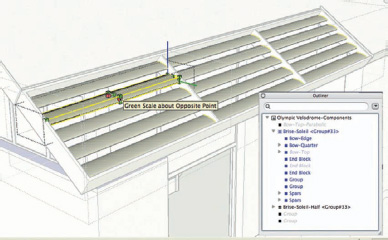
OVERVIEW FIG 1.15 Branching structure of nested components.
Managing the Display of Groups and Components
Imagine that you are working on an architecture project: Your model is made up from the different floors of the building, furniture, vegetation and plant, and technical equipment. In addition, you have put together various options for the building that you want to show to the client. Clicking around on all the components and groups to show or hide them one by one would really be an onerous task. Luckily, SketchUp makes the job easy by giving you the following tools.
The Outliner Palette
The Outliner displays the names of all the groups and components in your model. Using this palette you can select them, rename them, move them from layer to layer, turn their visibility on and off, etc., simply by selecting their names in the list and right-clicking on them (Ctrl-clicking on a Mac) and selecting Hide/Unhide. You do not even need to know exactly where they are in your model. What a time saver!
Let us have a look at the options for the Outliner palette in more detail:
• Make Unique: This option allows you to dissociate a single copy of the component from all the other instances. When you now edit this component, the other components from which it was derived will not be modified.

OVERVIEW FIG 1.16 The Outliner palette.
Tip
A nice touch is when you select many copies of a component: Clicking on Make Unique now will make all the selected components copies of a new component; modifying any one of them will affect all the other components that were originally made unique.
• Save As: This option lets you save the component in a library outside the current file.
• Reload: This option lets you replace a component with any other to be found in the library. The following are several applications for this feature of SketchUp:
• Quickly replace one object with another: Pieces of furniture, window frames, etc.
• Replace low poly, stand-in components by their more detailed counterparts when you want to render out an image or animation. This allows you to carry out the bulk of your work quickly and easily, by using objects that will not stress your graphics card, but still, in a few clicks, give you the opportunity to produce detailed images.
• Replace a project element with one of its variants, to gauge its impact on the rest of the model. In my opinion, this is the best method for managing project options in SketchUp.
• Major collaborative work can be made easier by subdividing a complex model into several simple components that are saved in the same directory. You can open each external component like a normal model that can then be modified and detailed by a team member. Each time that an external component is updated, it can be loaded into the master file. This method of collaborative project management is detailed in the case study of Takeshi Hashimoto (see Chapter 2).
• Zoom Extents: When you choose this option, SketchUp zooms in on the group or component so that it fills the entire Workspace. This would be ideal when you want to rapidly modify component.
Tip
In order to make the most of the Outliner palette, get into the habit of systematically naming your components and your groups logically and of using names that will be comprehensible to other users. In this fashion, you can rapidly select an element in a list and you will instantly know what group or component it belongs to.
The Outliner palette is not the only way to manage the display of groups and components. Here are some other options open to you:
The Layers Palette
Managing the display of groups and components is the chief task of the Layers palette.
Creating a New Layer
With the Layers palette open (from the Menu Bar, choose Window > Layers), click on thePlus icon to add a new layer. You can now click on the name of the new layer to edit it.

OVERVIEW FIG 1.17 The Layers palette.
Tip
By default, the visibility of any new layer created is toggled on. It is better to create all your layers before you create the scenes that will control how the layers are displayed. If you do it the other way around, you will need to update all your scenes in order to manage the visibility of your layers.
To change the layer that a group or component is on, use the Entity Info palette. You can bring up this palette by right-clicking (Ctrl-clicking on a Mac) on the group or component in the Workspace or in the Outliner.
You can also choose Window from the Menu Bar and then click on Entity Info. Click on the layers drop-down menu, and you can then assign the object to any of the layers in your model.
Tip
Do not forget: As long as Layer0 contains only edges and faces, everything will be OK! Only groups and components should be placed on other layers.
Tip
On a Mac, you can create a new layer simply by typing its name into the Layer field in the Entity Info palette.
Managing Model Variants
By assigning the different groups and components that represent a particular model variant to a particular layer, you can switch the different variants in or out using the Layers palette. However, using external components and the Outliner palette is actually a lot more practical and better suited to this task.
Managing Group or Component Visibility
By placing groups and components on distinct layers, you can easily manage their visibility by toggling their layer’s visibility on and off. If you often need to turn multiple layers on or off, then it is much more efficient to use scenes (see next page). For any given scene, you can determine exactly which layers are visible or hidden, something which is much more practical than manually switching layers on or off.

OVERVIEW FIG 1.18 Show/hide layers.
Creating Scenes
While, naturally, scenes are used for setting up different points of view in your model, they are also equally adept at managing the visibility of a group of layers. Rather than switching multiple layers on or off one by one in the Layers palette, you can perform the same task with a single click. How, exactly? If you have the Visible Layers option checked in the Properties to Update section of the Scenes palette, the visibility of the layers in your model becomes a property of that particular scene: SketchUp will remember which layers it has to show or hide for a particular scene.
The other options available for scenes are the display of hidden geometry and active section planes, the active style used, shadow setup, and the location of the axes. Here are some examples:
• You can record shadow studies at different times of the day (and make an animation of them).
• Record different camera views to produce plans and perspectives for presentations.

OVERVIEW FIG 1.19 The Scenes palette.
• Associate a different style with each view: For example, plans and sections should have a technical drawing style, whereas perspectives could have more of a hand-drawn feel to them.
Tip
In order to save only the camera position within a scene, untick all the options that you do not need in the Properties to Save section of the Scenes palette. You can quickly forget the fact that you have deactivated a layer, modified the shadows, or changed the style between two scenes. The result when you are rendering an animation can be… well… rather picturesque.
Displaying Your Model
In order to work efficiently, you need to limit the number of objects that are simultaneously displayed in your Workspace because SketchUp has problems when it needs to display large numbers of faces (i.e., when they reach around a million). Thanks to layers, scenes, and the Outliner, you can quickly and easily manage the display of the elements within your model.
Hide all the objects that you do not need for the task in hand. In architectural projects, for example, you could display all the walls that you want to modify but hide the furniture, vehicles, and people. One particular resource hog is 3D vegetation: A single detailed tree can easily contain as many faces as the entire rest of your project.
Only Display Shadows When You Need Them
You will have probably noticed that SketchUp still does not take advantage of multicore processors, nor does it use some of the more specialized functions of top-of-the-range graphics cards (we were on version 7.1 at the time of writing). While we wait for these features to be implemented, you will need to keep the load on the processor down in order to keep the navigation fluid and to conserve some processing power for certain cycle-hungry commands.
After you have turned off the visibility of unneeded elements, one of the best means of speeding up the display is to turn off shadows. Only turn them on when absolutely necessary, for example, when you are rendering out stills or an animation.
Apply the Right Materials to the Right Faces
On the screen, could you easily differentiate between a light beige coating, light beige paintwork, and SketchUp’s default material? Not easy, is it? You usually find yourself with two or three different SketchUp materials assigned to faces that should all have the same material. In order to avoid this situation, your materials should show a high level of contrast. By using this method, you can easily identify and correct any mistakes.
It is true that these contrasting colors are rarely realistic or even pleasing to the eye. Once you have used the Paint Bucket tool to add these colors to the appropriate faces, you will almost certainly want to change them to something a little closer to reality. The most simple method is to modify each contrasting material to make it look more like the actual material. However, it is often difficult to obtain exactly the right material appearance for each project.

OVERVIEW FIG 1.20 By using contrasting textures, you can rapidly identify faces carrying different materials.
Tip
Luckily, there is a plug-in that lets you replace one material with another, fr_Global_Material_Change.rb, created by TIG. Once you have placed it in SketchUp’s plug-ins directory, you can access it the next time that you start SketchUp. From the Menu Bar, go to Plugins > Global Material Changer. From the list that appears, select the material that you want to replace and the material you want to replace it with. The change will take place on every face in your model that carries the first material, even if they are nested inside groups and components. This is also another reason why you should give your materials names that are descriptive and easily understood.
When you apply a material to a face, any faces subsequently created with the Push–Pull tool or the Follow Me tool will have that same material applied to them.
Tip
Imagine that you are modeling a volume that represents a house. In the first stage, you draw some simple rectangles to indicate window and door openings and you apply a transparent material to them. Now, when you use the Push–Pull tool on the faces to model the window opening, the reveals will also have the same transparent material applied to them. It is a bit of a chore to go back and apply the correct material to the reveals.
It is far more practical to apply the material after using the Push–Pull tool.

OVERVIEW FIG 1.21 Results of the Push–Pull tool after the application of the material.
Choose a Simple Rendering Style for Efficient Navigation
If your model is composed of a large number of faces, you should avoid as much as possible the use of “sketchy” styles with hand-drawn edges. This rendering style is much more calculation-intensive for SketchUp and can lead to jerky orbiting, panning, etc.
Give Meaningful Names to Files, Layers, Components, and Scenes
Whatever names you choose to give your files, layers, components, scenes, or even styles, make sure that you employ a logical and consistent naming scheme. The scheme could be informed by the standards of your particular industry or your firm, your project’s stage of completion, or its location. The main thing is to be able to recognize quickly and without ambiguity what a particular layer, file, scene, etc., contains. Ideally, a person not familiar with your project should be able to easily understand what each name represents.
Example: A unique suffix representing category–name–number.
The following is a nonexhaustive list of elements that could appear in a logical classification:
• Name of project
• Participant: Architect, designer, technician, etc.
• Project area: Conception, structures, special finishes, etc.
• Type of work: Masonry, public works, electricity, etc.
• Location: Lot W, building X, room Y, cupboard Z, etc.
• Development phase: Sketch, preproject, project, construction, etc.
• Alphanumeric code: 01, B52, etc.
Tip
In the Windows version of SketchUp, the width of the Scenes palette is fixed, and so you should limit your scene names to 40 characters so that you can view the whole of the name at a single glance.
Communicate
Publish a Guide That Explains Your Working Methods and the Naming Conventions Used
Ideally, every person taking part in your project should be able to join it at any point, without having to pull his/her hair out trying to understand the working methods and the naming conventions used by his/her predecessors. Notice I said “ideally.” In practice, too few enterprises have implemented an efficient and logical working process. Is yours one of them?
Certainly, the preparation of such a document takes time, and changing the working habits of dyed-in-the-wool (and often blasé) users is never easy. “We’ve always done it this way… why should we change?”
Use the Same Point of Reference for All Project Files
Try to keep the same origin point for the axes in all project files, whatever be their origin. In this way, it is much easier to import and export plans and 3D models between the other CAD applications used in the project.
Tip
If this is impossible, use a reference point (a simple line will suffice) that will allow you to precisely move the different imported objects into their correct position in your SketchUp model.

OVERVIEW FIG 1.22 Reference guides for moving imported elements.
Check Every Stage of the Project Before Adding Any Details
You know that the simpler your model is, the easier it is to modify. Before adding any details, check the model, as far as possible, with the clients and the other project participants.
Share Your Component Libraries
Do you collaborate regularly with the same partners on certain projects? Then you should use the same components and working methods to save time for all concerned. Why not publish the rules for creating and using components in the good practice guide mentioned previously?
Save
Human error, a software or workstation crash… the risks that your computer data faces are real, and SketchUp is not exception to the rule. It is therefore essential to save your SketchUp files regularly and in an organized manner.
Understand SketchUp’s Automatic Backups
By default, SketchUp automatically saves your files at regular intervals and creates a backup file of the previous version with the extension .skb.
Tip
Has your model become a chaotic mass of polygons, thanks to an ill-advised modeling operation? Is the Undo command not helping? You could recover a part of your work, thanks to the backup file. Simply change the .skb file extension to .skp to make it readable by SketchUp.
With complex projects, the time taken to create the model can become relatively long. Unless SketchUp is crashing frequently, do not set the automatic backup interval to less than 15 minutes. To change the automatic backup interval, from the Menu Bar, choose Window > Preferences > General, where you will find the option for setting this. You will have to decide the length of this interval for yourself (frequent crashes or not).
Save at Each Key Stage
Save every time that you finish an essential part of the project. Try, also, to get into the habit of saving your file before using any command that could cause SketchUp to crash (this is particularly the case when you are using plug-ins).
Save Under a New Name
Save each key stage with a different file name. This will allow you to easily retrace your steps. Who knows if their client will ask them to start over from an earlier concept stage?
Save Your Files in Various Locations
SketchUp is not the only thing that can crash: The same is also true for your hard disk, and so you should get into the habit of saving the new files to an external storage medium (tape, external hard drive, CD, or DVD) at least once a day. If your file sizes are not too big, you could also save to your personal web space or to an online backup provider.
Tip
To assist you in this task, there are various pieces of software that allow you to manage incremental backups. These programs look for all the new or modified files and then transfer only those to the backup device, for example, SyncBack SE or Cobian Backup. Mac users using OS X 10.5 or later can, of course, take advantage of the built-in Time Machine backup system.