Chapter 9

SketchUp Powers Theatre Scenic Design
Kim A.Tolman, a native of Germany, is an award-winning scenic designer. She relocated from Cologne, Germany, to the San Francisco Bay Area, California, in 2001. Kim brought along her scenic design and hand-drafting skills that she had refined in German theatre and opera to California, where she quickly made the transition to computer-aided design. Kim became a user and advocate of SketchUp, which she enjoys for its power and ease of use. She was one of the only 300 individuals worldwide who were chosen to attend Google SketchUp 3D Basecamp 2008.
Kim designs at theatres throughout the United States and is a member of the United Scenic Artists, Local United Scenic Artists (USA) 829, and International Alliance of Theatrical Stage Employees (IATSE). Her Web site is http://www.kimtolmandesign.com
Project: Scenic design for A Midsummer Night’s Dream at Center REP Theatre, Walnut Creek, California.
Tools: SketchUp Pro 7; Style Builder; LayOut; Render Plus RpTools; various Ruby Scripts, including Move to Origin and Angular Dimension; AutoCAD; Photoshop CS; Adobe Acrobat.
In theatrical productions, the primary client is the director. It is the task of the scenic designer to collaborate with the director to help bring the director’s vision for the production to the stage. The director relies on the scenic designer to create and develop visual concepts. Director Michael Butler wished to stage the classic play, Shakespeare’s A Midsummer Night’s Dream, in a nontraditional way. Butler says, “Midsummer has two distinct worlds: that of the Court with all its rules and constraints, and the forest, which is anarchic, mischievous, erotic. I thought of the play as a gleeful and unruly rebellion of the imagination against all those forces that tell us what we are supposed to do. I wanted also to play with strange intersections of dream world with real world, like vines invading our hair while we sleep. So rather than keep the two worlds separate, Kim and I wanted the world of the Court to be taken over and transformed by the forest, much the way it might happen in a dream where the familiar can suddenly alter in strange ways.”
Additionally, the director and scenic designer were inspired by pop-up books. Butler continues “Kim has an extraordinary collection of macabre pop-up books from all over the world and we both loved the two-dimensional (2D) and yet weirdly convincing effect of their transformations.”
Scenic Designer Kim A. Tolman, who often uses SketchUp in her design work, introduced Butler to the 3D modeling software, which they used as a collaborative tool. Kim says she likes the ability of SketchUp by which she can quickly communicate creative ideas with the software, as well as SketchUp’s ease of editing for instant manipulation of designs.
Project Context
For A Midsummer Night’s Dream, I had approximately one month to deliver my first concept sketches. I worked in collaborative sessions with Director Butler, inputting and manipulating our ideas in SketchUp and exporting the images to PDF with Adobe Acrobat to generate concept color renderings.
When designing for theatre productions, the scenic designer has a standard set of deliverables (specified in the following list). After the design is approved by the director, the scenic designer needs to produce the drawings and renderings from which the technical director’s team of carpenters can build the scenery and the scenic artists can paint. The scenic designer typically has 1–3 months from the approval of the design till the delivery of all drawings and renderings. The final deliverables are as follows:
• Set concept color renderings
• 3D computer model (or to-scale physical model)
•Ground plans, centerline sections, elevation drawings and sections (AutoCAD or hand-drafted ones)
• Paint elevations (computer-generated and/or hand-painted ones)
• Color samples
Technical Aspects
SketchUp has a primary place in my design toolbox. I find it not only an excellent means of visualizing and creating a design but also a powerful tool for communicating stage design concepts, as well as the final design to the director and other members of the production team (lighting designer, costume designer, technical director, property designer, scenic artist, and others).
The scenery for A Midsummer Night’s Dream prominently featured two walls that leaned back from their upright positions via the use of pneumatic piston supports. SketchUp allowed me to effectively and easily communicate this function to the technical director, who was charged with the task of devising the system for moving the walls down and then back up, representing both the chaotic world of the forest and the rigid Athenian court.
I use SketchUp to deliver the 3D computer model to the director and the creative team. On the 3D computer model, I used Render Plus RpTools for easy layout of 3D components. RpTools allows me to Select, Place, Move, Copy, Rotate, Mirror, Stretch, and Aim components.
And because I create to-scale with accurate measurements, I can also export the SketchUp model to AutoCAD to use as the basis of the ground plan, centerline section, and elevation drawings. This is a major labor-saving benefit of using SketchUp.
For the paint elevations, I export from SketchUp to Photoshop, where I manipulate color and shading and then obtain a printout on paper. I then paint over the paper printouts to get the final desired colors, shading, and textures. These paint elevations are used by the scenic artist as a guideline in painting the finished scenery pieces that were built by the technical director’s team.
New Approaches
In theatre applications as a scenic design tool, SketchUp is not only a time-saver for the scenic designer but also a powerful creative and communicative tool. Director Michael Butler is typical of the collaborators with whom I have worked and introduced the power and flexibility of SketchUp. Another collaborator, Director Jon Tracy says, “SketchUp revolutionized the preproduction process for me.” Director Robin Stanton says, “It takes the collaboration to another level. The aesthetics and mechanics can be easily and effectively communicated to industry veterans as well as early career artists effortlessly.” Director Joy Carlin adds, “It taught me how to look at the performing space from every conceivable depth and angle, making it so much easier for me to imagine how the actors could move around, make exits and entrances, where the best focus points might be, and so on.”
Director Nancy Engle had even more to say about the software: “SketchUp has made scenic design discussions infinitely more productive. It clearly communicates the look and feel of the design and facilitates instant feedback from directors and other members of the design team. As a director, I appreciate the ability to take a 3D look at the complete stage setting. I can see everything the audience sees and everything they cannot. SketchUp allows me to live in the scenic environment, before I ask the actors to inhabit it. And SketchUp saves time, money, and energy in communicating the scenic design to the craftsmen who must implement the design.”
Step 1: Preparation/Start of Scenic Design Project
Objective: To initiate the project. Data: Script, project time line.
Tools: Internet, word processor (to read digital script), pencil and paper.
The first steps to be followed in starting the design process are as follows:
• Reading the script: digital and/or hard copy
• Meeting the director
• Deciding on a design concept
• Performing research
• Reading the script again: digital and/or hard copy (generating very rough, first sketches/ideas/ground plans on paper)
Step 2: 3D White to-Scale Model
Objective: To get familiar with the theatre space.
Data: Documents submitted by the theatre: ground plan, centerline section, additional important house measurements, stock inventory list, etc. Tools: Supplies to build a physical 1/2"-scale model of the theatre.
I built the model from drawings received from the theatre. The physical “white” model helped the director and me to “play” with the space. I created rough set pieces and a rough layout.
Note: In most scenic design projects, the use of SketchUp to build a 3D computer model has replaced the need to build the to-scale physical model described here.
Step 3: Recreating the Theatre Building in SketchUp
Objective: To get familiar with the space – an essential step in creating a concept/design – and check possible reuse of 3D theatre model for future projects at the same venue.
Data: Documents submitted by the theatre: digital ground plan, digital centerline section, additional important house measurements, stock inventory list, etc. Tools: AutoCAD, SketchUp Pro.
I import the ground plan and centerline section into SketchUp, and then scale the model with the Tape measure tool. The crossing point of the ground plan’s centerline and the plaster line should be the origin. I turn each plan into a group. Then I right click on the plans and choose Lock from the pull-down menu to lock the important documents. (Note: Locked plan will turn red.) This step will protect the imported drawings and prevent me from erasing lines accidently. I start drawing on top of the ground plan, referring to the centerline section for height dimensions.

FIG 9.1 Image of the ground plan and centerline section in place.
Tip
From the very beginning, I put everything on layers, grouping things by adding a word or a letter in front of the layer name, for example, IMPORT–Ground Plan and IMPORT–Centerline Section. All theatre architecture starts with “T–”Proscenium, T–Walls, etc.). All furniture starts with “F–” (F–Sofa, F–Bed, etc.). This is a good way to keep the model organized by grouping similar items. I start recreating the space step by step, putting objects on layers using the method outlined in Step 3.

FIG 9.2 Empty model box.
Step 4: 2D Sketch
Objective: To communicate a preliminary concept/idea to the director (and possibly other members of the production team) and also provide support for discussions about design process.
Data: SketchUp model of theatre, first hand-drawn sketches, notes from meetings with director.
Tools: SketchUp Pro, SU Style Builder.
I started modeling first concept ideas using initial hand-drawn sketches as support. I first created a scene for each point of view: top view, section cuts, and work view (a view of the model with unnecessary layers turned off). This first step of modeling is not so much about getting all the details right than about quickly expressing the general concept. The two walls were created with the Line tool and the Push/Pull tool. I then turned each wall into a group. The arrangement of the wall angles in slanted position was created with the help of the compass command. To check accuracy and take printouts of quick views with dimensions, the Ruby script Angular Dimension served as a great additional tool. Sometimes, I create set pieces and props in a separate model and later insert them to the main model. When I create a separate component (e.g., the potion flower in A Midsummer Night’s Dream), I always create the insertion point at the origin. The Ruby script Move To Origin can be very helpful in this.
Another great help is Render Plus RpTools, which I constantly use to quickly resize components, groups, and other elements.

FIG 9.3 The model at Step 4.
Nearly everything in the model is either a group or a component. I worked with standard theatre component measurements from the beginning (e.g., 4" × 8" flats and the 18" rule for step units). Because standard component dimensions were used, when the preliminary design concept was approved, I could build the rough model without redoing everything. When the design was finished to the point where design ideas could be communicated and presented, I printed one or several views of the model as images. Before doing so, I created a new scene and named it Midsummer/Sketch. I then created a new style that applies only to this scene. The style was created in SketchUp Style Builder. I created the style by using hand-drawn sketchy strokes first and scanning them to create an image file, which I edited in Photoshop and pasted back to the confines of the template boxes in SU Style Builder.

FIG 9.4 Rough sketch.
Tip
The rough “sketchiness” of this particular style helps to keep the creative process more open and not so “nailed down” when presenting it to the director and the rest of the production team. It looks very much like a hand-rendered sketch, rather than a technical drawing. In fact, SketchUp lets you create images that look as if they were sketched with all the beautiful imperfection of the human hand. In addition, rough ground plans can be printed simply by using the Top View option in SketchUp. These sketches and preliminary grounds plans are usually enough information for an early design meeting.
Step 5: Presenting Preliminary Design Sketches and Ground Plans
Objectives: To obtain support for discussion with the director and the creative team, and approval before more detailed 3D modeling and design continuation.
Data: Printed sketches and ground plans.
Tools: SketchUp Pro.
I bring the preliminary computer model to the production meeting in case clarification or possible instant manipulation/modification/editing are needed.
Step 6: Preliminary Design Approved – More Detailed Modeling
Objectives: To refine and, possibly, revise design.
Data: Meeting notes, preliminary SketchUp model.
Tools: SketchUp Pro.
I start adding more detail to the design, for example, using the Follow Me tool for all trim, crown moldings, and pipe.
Tip
When I work on a particular group or component within the model, I usually isolate it from the rest of the model. This makes all-around access easy. Also, it is less taxing on CPU and RAM resources. I go to View, select Component Edit from the drop-down menu, and select Hide Rest of Model. To Unhide, I need to only uncheck the latter option.
To create crown molding, I simply draw a profile or pick one from the molding supplier’s catalog (check if a CAD drawing is available on their Web site for importing purposes) and attach it to the top of the wall. I then select the edges to which I want to apply the molding, and then pick the Follow Me tool and select the profile.
Step 7: Adding Colors and Textures
Objectives: To refine and, possibly, revise design.
Data: Meeting notes, preliminary SketchUp model.
Tools: SketchUp Pro, Photoshop.
I apply materials from the expanded SketchUp library. I then export the front view of each set element as a JPG image.
In Photoshop, I add highlight and shadow, and modify textures as needed. I then project images back into their original space in the model.

FIG 9.5 Creation of crown molding.
Tip
It is a good idea to always be on the lookout for images to expand your SketchUp library. For example, I had a photograph of a stone wall with cracks and textures that I wanted to use for my A Midsummer Night’s Dream model and possibly for future projects. To use this photograph, I opened a new SketchUp file, went to Top View, selected File, and browsed for the image. I checked Use as image option and imported it to the model. I then right-clicked and exploded the image. Then I clicked on the Paint Bucket to display Materials, selected the Home (In Model) tab, and saw the imported image in the Materials display. To display the secondary selection pane with existing Libraries, I clicked the button near the top right of the Materials display. The display expanded to show existing libraries and I dragged the new material image into the appropriate category. Categories (new directory folders) can be created within the Materials folder that lies within SketchUp’s program files on the root directory, for example, C:Program Files GoogleGoogle SketchUp 7MaterialsStone.
I then used SketchUp LayOut to create the design presentation.

FIG 9.6 Model without walls.
Step 8: Presenting Final Design, 3D Computer Model, SU LayOut Presentation, and Updated Ground Plans
Objectives: To present the final design, 3D computer model, SketchUp LayOut presentation, and updated ground plans to the director and the creative team.
Data: Printed LayOut color renderings and ground plans, and CDs with model and SketchUp viewer for production team.
Tools: SketchUp Pro.
I use the finished SketchUp 3D model to present the design. Because scenes have been created, the slideshow option in SketchUp can be used for presentation. On some occasions, I project the presentation onto a screen.
Step 9: Final Design Approved – Final Ground Plans and Center Line Section to Be Created
Objective: Create technical drawings.
Data: SketchUp model.
Tools: SketchUp Pro, AutoCAD.
The ground plan is created as follows: From the Top View in SketchUp, I go to File, Export, and 2D Image, and select.dwg file. I then open the .dwg file in AutoCAD and finalize the drawing. Usually, I “clean up” the drawing a bit. A few examples for this are given here. Often, there are extra lines stacked on top of each other that are remnants of the conversion from 3D to 2D that I need to erase. I redraw circles and arches (they are segments when imported from SketchUp and it is difficult to put dimensions on them), and I put areas of the drawing on different layers in order to organize the drawing and create line weights. For example, I put all scenery on its own layer to differentiate it from other elements.

FIG 9.7 Layout presentation.
The centerline section is created as follows: I create a section plane at the centerline in SketchUp. I then go to File, Export, 2D Image, and select .dwg file. I open the .dwg file in AutoCAD and finalize the drawing.
Step 10: Final Design Approved – Elevation Drawings to Be Created
Objective: Create technical drawings.
Data: SketchUp model.
Tools: SketchUp Pro, AutoCAD.
I exported the components from SketchUp into my project folder called Set Elements. Each set piece was processed separately. I selected Camera > Parallel Projection. I then opened each component as a new model and exported plan, side, front, and section views, each as a separate .dwg file. I then imported each .dwg file into AutoCAD and arranged the elevation drawings.
SketchUp also allows the exporting of isometric views to AutoCAD for more complicated pieces and better communication with the technical director. Simply select the Iso View Command, go to File option, and select Export from the drop-down menu; further, select 2D Graphic, destination folder, and Export Type as AutoCAD DWG.
Step 11: Final Design Approved – Paint Elevations and Color Samples to Be Created
Objective: Create guidelines for the scenic artist. Data: SketchUp model.
Tools: SketchUp Pro, Photoshop, brushes and paint.
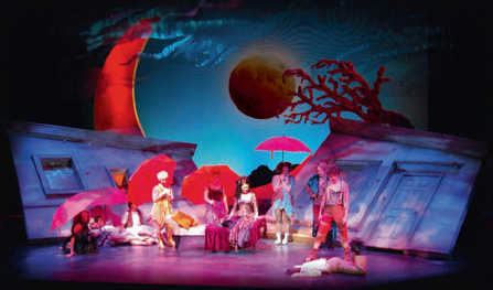
FIG 9.8 Show pictures.
From the folder Set Elements, I processed each element separately by opening the element in SketchUp. I selected Camera > Parallel Projection. I then exported desired views to JPG image format. Then I opened JPG in Photoshop and added desired colors, shadow, highlight, and texture. I printed out to scale on high-resolution paper. Then I did final modifications with brushes and paint.
Further, I used brushes and paint to create color samples to be used by scenic artists.

FIG 9.9

FIG 9.10
Conclusion
SketchUp was a natural choice for this project, and it is useful for any scenic design project. SketchUp was especially helpful in
• Allowing me as the scenic designer to quickly prepare the layout and edit multiple scenic concepts during collaborative creative sessions with the director
• Easily communicating the scenic design to all members of the production creative team
• Exporting SketchUp models to AutoCAD, which is a major time- and laborsaving feature for a scenic designer
A Midsummer Night’s Dream opened at Center REP Theatre on April 1, 2008, for a very successful run. Both Director Michael Butler and the audiences were quite pleased and charmed by the set I designed with the help of SketchUp.
Resources
Software
Autodesk AutoCAD
Adobe Photoshop CS
Adobe Acrobat
SketchUp Plug-ins
SU Style Builder
LayOut
Render Plus RpTools
Various Ruby scripts, including Move to Origin and Angular Dimension