
OVERVIEW 2

When SketchUp Misbehaves…
You know how it is – suddenly, you cannot get anything done: SketchUp is misbehaving! That operation that you wanted to perform – the one that seemed so simple – is proving to be impossible. Your model looks as though it has been knocked over by a bulldozer. Your model disappears and reappears according to your camera angle… just what on earth is going on?
SketchUp has a well-deserved reputation for being simple and intuitive, but nevertheless you still need to know some tips and tricks to avoid these snarl-ups or, worse, the loss of several hours of work. Here are several situations that you may have the misfortune to encounter:
But… It’s Sticking!
When you first start modeling with SketchUp, you will quickly encounter the following situation: You simply cannot move a selection of lines and faces perpendicular to another collection of lines and faces with which it shares a common face or edge. Yet you have carefully selected the elements that you want to move and you are using the Move/Copy tool, but without success.
Your selection appears to be “glued” to the common face it shares with the other collection. What can be going on here?

OVERVIEW FIG 2.1 The selection cannot be moved off the plane of the shared face.
In SketchUp, when two collections of lines and faces share a common face or edge, that face/edge is unique: it cannot be in two places at the same time.
The solution for “unsticking” these two collections of lines and faces is to select the collection of lines and faces that you want to move and then group them or turn them into a component. By doing this, you isolate the faces and edges within the group or the component from the rest of the model: a second face or edge is created automatically. If you choose to make a component, do not forget to make sure that the Replace Selection with Component check box is ticked.
If your two collections of faces and edges share a common bottom face, do not forget to draw in a line to split this common face into two separate faces.

OVERVIEW FIG 2.2 Grouping to disassociate a collection of lines and edges.

OVERVIEW FIG 2.3 If necessary, split this common face into two separate faces using the Line tool.
You Cannot Create a Face
There are three classic situations that can stop SketchUp from closing a face:
1. Fewer than three edges are meeting at a point
Zoom in on the corner points and make sure that there are no gaps. This is very often the problem with plans imported from other CAD programs. To solve the problem, you can always redraw each edge one by one using the Point inference.
2. The edges are not lying in the same plane (are not coplanar)
You can use the Constrained On Line from Point inference to move each end point in alignment with a single reference point. (You may need to redraw one of the edges of your outline once all the points are coplanar, in order for the face to properly close.)
3. One or more of the edges are actually inside another group or component
If this is the case, simply draw the missing edges.
Attention
Until version 7, SketchUp did not automatically split edges that crossed over each other, even if they were lying in the same plane. To correct this problem, you need to redraw the edges up to their intersection. In version 7, SketchUp automatically subdivides any edges that cross, creating the corresponding faces. Neat! Unfortunately, however, this does not work for imported plans.
An Outline You Have Drawn Will Not Cut a Face
Usually, you can draw a rectangle on a face and watch as its edges go thin, indicating that you now have two new faces. You can then use the Push–Pull tool to extrude either of the new faces. But sometimes, things do not go as planned. Here are some possible causes:
1. The face that you are drawing is actually inside another group or component
In this case, the only solution is to enter the group or components to edit it, making sure that you are drawing on a “raw” face. Be careful that your group or component does not contain any other nested groups or components.

OVERVIEW FIG 2.4 Drawing on a group or component will not cut the face.
2. What seems to be a planar face is, in fact, a series of smoothed facets
To find out whether this is the case, from the Menu Bar, choose View > Hidden Geometry. If it really is a smoothed surface, the solution to being able to cut it is to create a volume with the same dimensions as your cutout. Then group the volume and move it into position on the surface. Right-click (Ctrl-click on a Mac) and choose Intersect with Model from the contextual menu. Erase or hide your volume, and your curved face will be cut.

OVERVIEW FIG 2.5 Cutting a smoothed surface with the Intersection tool.
3. You are not actually drawing in the plane of the face
Make sure that your drawing tool is displaying a dark blue dot and that you are getting the On Face tool tip. If you need to, you can temporarily align SketchUp’s axes with this face to make the task easier: Right-click (Ctrl-click on a Mac) and choose Align Axes from the contextual menu.
Optimize Imported Faces and Edges
Drawing directly on the edges and faces of an imported CAD file is definitely not recommended: The problems you encounter are manifold and often have no easy solution.
A good procedure is to group all the imported edges and faces and then trace over them using the drawing tools and the inferencing engine. If you absolutely have to work directly on imported CAD files, then Todd Burch has developed several plug-ins (most of which have to be paid for) to automate certain tedious tasks.
• IntersectOverlaps helps to split any edges that cross over each other.
• CloseOpens looks for any lines that should be touching at their end points and closes them.
• DeleteShortLines erases any little lines that go past end points. This is particularly useful for making sure that the Point inference does not get confused.
• ExtendClosedLines finds any lines that have not met their end points and elongates them to the nearest point of intersection.
• MakeFaces analyzes your model and automatically creates any missing faces.
Autofold to the Rescue
Have you ever come across an edge that obstinately refuses to move on the Z axis? It will move no problem on the X–Y plane, but it is impossible to move it vertically. What is going on here? It is clear that a certain amount of subdivision of faces is going to be necessary to get this operation to work, but SketchUp will not do this automatically. This is where Autofold comes in: You simply need to hold down the Alt key (Cmd/Apple key on a Mac) before moving the recalcitrant edge.

OVERVIEW FIG 2.6 Autofold used with the Push–Pull tool.
Display Problems or Truncated Models
This display error, where a part of your model disappears, is one of the most common questions asked on SketchUp forums.
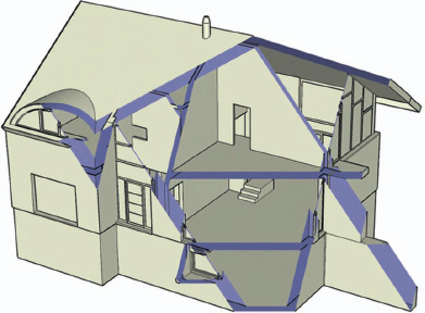
OVERVIEW FIG 2.7 A part of your model disappears for no apparent reason.
When you use the Orbit tool to tumble your model, you can sometimes find your model truncated, as if it is being cut by a section plane. This problem can have several causes, and there are several solutions that I will detail below.
The Causes of the Truncated Display Problem
The problem has been christened with the seemingly innocuous name of “Camera Clipping Plane.” However, its causes can be many and varied…
Below, you will find different situations that can cause the problem and the solutions to them. I have decided to start with the most common cause, but read through the whole list and choose the solution that best suits your case. It is worth determining the cause precisely because some solutions require modifications to the model.
Your Model Is Situated Far Away from the Origin of the X, Y, and Z Axes
This problem is often found when you are working with plans imported from AutoCAD or another piece of CAD software. When you are working in CAD and using surveyor’s plans, your project can sometimes be situated very far away from the point of origin of the X, Y, and Z axes. Once imported into SketchUp, it is common to get display problems when there are elements present that are a great distance apart from each other. This is often the case with surveyor’s marks or with segments that have been placed to be used as reference points.

OVERVIEW FIG 2.8 The model is situated far away from the origin point of the axes.
The first solution has you erasing all the “forgotten” elements from the rest of your model. If that still does not work, move the entire project and center it over the axes origin. Before moving everything, make sure that there are not any hidden groups or components (from the Menu Bar, choose Edit > Unhide > All) or any layers whose visibility has been switched off. If you do not do this, these elements will not get moved and the problem will persist. To make the task easier, you can use the MoveToOrigin plug-in to automate this task. Sometimes, this approach will not cure the problem: Sometimes, certain elements that are difficult to detect – or are even invisible – are present at the outskirts of your Workspace and will continue to cause these display problems.
To identify and eliminate these elements, follow these instructions:
1. Click on the Zoom Extents icon Crtl+Shift+E (Cmd/Apple+Shift+E on a Mac) to make sure that your entire model fits within the Workspace.
Wide Field of View
SketchUp’s default camera field of view is 35 degrees. Sometimes, you can type in too high a value by mistake, getting a wide-angle lens (or a fisheye for photographers).
Perspective Is Off
The truncated model problem can appear when the model is being displayed in parallel projection. Click on Zoom Extents to correct the problem.
The Scale of the Project Is Too Large or Too Small
SketchUp has problems working with very small unit sizes. In this case, it is often the whole of the project that will disappear rather than simply displaying the truncation. The solution is simple: Change the scale.
To quickly change the scale of the entire project, draw a help line 1 unit long (inch, foot, yard, or whatever) and measure it using the Tape Measure tool. The length of this line will appear below right in the Value Control Box (VCB). Type in the new length (for example, 100 if you want to scale it up by 100 times) and click on Yes when SketchUp asks you if you want to resize your model.
Attention
Any components in your model that have been loaded from an external library will not be scaled using this method. You either need to explode them first or scale them up afterwards – but that can be a chore.
Incompatibility with Your Graphics Card
Certain graphics cards do not manage the type of OpenGL acceleration used by SketchUp very well. To find out if this is the cause of your problems, in the Menu Bar, go to Window > Preferences > OpenGL and then untick the Use Hardware Acceleration checkbox. SketchUp and your processor will then take over the duties of calculating the images to be displayed on your screen. For users who work daily with SketchUp, this solution brings with it a display slowdown and a subsequent loss of productivity. Your only option in this case is to consider the purchase of a graphics card that handles OpenGL correctly.
Before you change your card, make sure that your drivers are up to date by downloading them from the manufacturer’s Web site. You never know…
For more information concerning the choice of the graphics card that works well with SketchUp, you can visit Google’s webpage on the subject: http://sketchup.google.com/support/bin/answer.py?hl=en&answer=36252.
What? Still Not Working?
If your file resists every attempt at solving this display problem, the only solution that I have found is to do a Copy–Paste into a fresh SketchUp file. The problem with this approach is that you lose all your scenes, but at least the problem is solved, and you can work efficiently with your project again.
Tip
To get your scenes back, you can use the PageExIm.rb, which allows you to export your scenes in .sup format and to reimport them into another SketchUp file.
Faceted Surfaces When You Want Smooth
Faces formed from circles or arcs produce smooth surfaces when they are extruded with the Push–Pull or Follow Me tool. This is not always the case, however, with arcs, circles, or polylines exported from a CAD program. By default, arcs are made up of 12 segments, whereas circles have 24. Before creating a volume starting with an arc or a circle, you can modify the number of sides in the Entity Info palette. Once the face is extruded, it is impossible to change this value.
If you get a faceted surface, you can still select the edges that you want to smooth, right-click (Ctrl-click on a Mac), and choose Soften/Smooth Edges. Still not working? Simply increase the Angle value in the Soften/Smooth Edges palette that appears after you carry out the previous command.

OVERVIEW FIG 2.9 Softening edges to produce smooth surfaces.
Your Model Is Completely Deformed
Who has not experienced this? You carry out a move or a rotation operation, you change the camera angle, and… oh no! Your model resembles Quasimodo on one of his bad days. But the usual cause of this problem is often that you have moved faces or edges that were hidden when you made your original selection. To avoid this catastrophe, try using the X-Ray face style after you have made your selection. You can then make sure that you have selected only the elements that you want to move. Any faces or edges that have been inadvertently selected can be removed from the selection by using the Arrow tool in combination with the Shift key.

OVERVIEW FIG 2.10 Check your selections in X-Ray mode.
If you only notice the damage much later, you can always use the Undo command Ctrl+Z (Cmd/Apple on a Mac) to go back to the stage where it all went wrong.
If you have already saved your file and quit SketchUp, there is still a glimmer of hope for you: By default, SketchUp backs up your model in files with the .skb extension. You can try renaming this extension to .skp to see if the backup file corresponds to a stage before the mistake was made. These backup files are found in the same folder as the .skp files.
Correcting a deformed model often takes more time than simply erasing the mess and modeling from new.

OVERVIEW FIG 2.11 Flickering effect when two faces are coplanar.
Flickering Faces When Using the Orbit Tool
This effect, which can ruin a presentation or an animation, happens when two different-colored faces are superimposed on each other so that they are occupying the same space. SketchUp, not knowing which faced a display on top, displays them alternately to draw your attention to the problem. To correct this effect, erase the part situated at the intersection of one of the two faces.
This effect can also occur when you draw a face on top of another face that is part of a group or component. In this case, one solution is to move the face by a tiny amount so that the faces are no longer coplanar. The other, better solution is to give a slight thickness to the face using the Push–Pull tool.
SketchUp Prints Badly
Even though your image may look superb on the screen, your printed drawings may leave something to be desired. In this scenario, check your printing setup and, more particularly, the Print Quality settings situated at the bottom right of the Print dialog box. If the printing quality selected is Draft or Standard, change it to High Quality at a minimum.

OVERVIEW FIG 2.12 Setting the printing quality.
Line Thickness and Image Resolution
Even if your chosen display style looks perfect on the screen, it may not look so good when you are printing or rendering images at high resolution. Basically, the thicknesses of the edges are dependent upon the resolution of the image. What looks like a lively, hand-drawn line at low resolution will lose its thickness (and, therefore, its hand-drawn appearance) as the image resolution increases.
Get into the habit of testing the results of increasing the resolution before rendering out a long series of images or an animation. If you cannot find a style that suits your illustration, you still have a solution of creating one yourself using the Style Builder that comes with Google SketchUp Pro 7. However, the line thickness that you can use is limited to 16 pixels.
Resources
Scripts
Plugins IntersectOverlaps, CloseOpens, DeleteShortLines, ExtendCloseLines, MakeFaces, MoveToOrigin, by Todd Burch. Available at www.smustard.com.
Plugin fr_pageExIm.rb, by Rick Wilson. Available at http://www.crai.archi.fr/RubyLibraryDepot/Ruby/FR_cam_page.htm.