
Chapter 2

Te Wero Bridge Competition in Auckland, New Zealand
After studying under Peter Eisenman, Elizabeth Diller, Ricardo Scofidio, and John Hejduk, Takeshi Hashimoto graduated from The Cooper Union School of Architecture (New York USA) with a B. Arch. in 1992. He then moved back to Tokyo and established Hashimoto Architecture Studio in 1996.
Project: Te Wero Bridge in Auckland, New Zealand.
Tools: SketchUp6 Pro, Podium, Photoshop CS3.
The project started as a two-stage international competition organized by the city of Auckland, New Zealand. The Te Wero Bridge is a swing bridge that connects the central business district and the Wynyard quarter (also known as “the tank farm,” it is a 35-hectare reclaimed landmark area surrounded by water), integrating the old and new cities while providing boat access in and out of the Viaduct Harbour marina.
The new bridge needed to span a maximum of 100 m, carrying two lanes each for vehicles and pedestrians and light rail or similar passenger transport systems for use in the future. From its closed position, the bridge had to fully open in 30 seconds, making a minimum 35 m clearance to let boats pass.
After being selected as one of four finalists in the first-stage competition, I teamed up with TILT group (an amalgam of various international firms, led by Pete Bossley Architects of New Zealand) to complete the second-stage competition. The thirty-five-million dollar budget seemed a bit short for a bridge of this scale and function, and as a consequence, our team had to give up some of the fancier options such as carbon-fiber composite as a main material for the bridge (there was an Italian yacht designer in the team, who specialized in carbon-fiber).
Project Context
As this was a competition project, all the usual constraints of competitions (time, budget, free labor…) weighed on us just as heavily as they would do on others. However, since we were preparing the first stage of the competition alone, the limitation of time was probably the biggest constraint of all.
As a consequence, before starting the design of the bridges and making renderings of them, we had to make many choices based on questions of time efficiency.
Although it was a competition for the design of a swing bridge, the only deliverables that the brief called for were a few still images (renderings), 2D drawings, and texts on one A1 sheet. Submission of animations was not required in the first stage of the competition. Of course, if you have a structure that moves, ideally you want to show it in motion, which we did with modo animations and movable models in the second stage of the competition, when we had more time and budget, but there was not enough time to do animations in the first stage. We had to live with static designing, and so we started thinking of ways to simulate the movement with still images in a sequence.
Technical Aspects
Within the time limit set for the competition, our office was to do all the designing, modeling, and rendering in-house. Knowing that the combination of SketchUp and Podium would do these things rather efficiently – we were familiar with both programs prior to entering the competition – it was natural for us to select them as our main design tools for this competition.
After we decided to have eight bridges instead of one as our scheme, we started setting up the drawing structure in SketchUp. Since our scheme had many variations of one element, a ‘finger’ of the bridge, we thought SketchUp’s component instances feature would work perfectly at the design study level, especially for quick design evaluation.
This meant:
1. Simultaneous modeling by a team:
SketchUp does not have an advanced Xref (external references) function. However, it is possible to divide the main project model into a series of submodels and work on them simultaneously as a team. Of course, we were going to use component instances, but with a bit of know-how, they can become a very sophisticated tool for group designing.
2. Easy design evaluation of bridge forms:
The position and sizes of the eight bridges were pretty much fixed at the early stage of design. We needed to know how their formal variations affect the views from various viewpoints, at different stages of their open/close cycle. The second part of the following steps deals mostly with setting up the file structure for quick design evaluations.
3. Quick rendering of still images:
We picked Podium as our renderer because it has a very fast rendering engine, and it requires no importing/exporting of files as long as it is used with SketchUp. Converting files from one piece of software to another is usually a very time-consuming, painstaking process, even when it claims smooth file conversion. So being able to create renderings within SketchUp was a big plus for us.
Other software used to complement SketchUp and Podium were Vectorworks (2D drawings, annotations, and page layout) and Photoshop (fine-tuning of renderings from Podium and adding Depth of Field [DOF] effect with layers). I also used Moment of Inspiration to create a couple of form studies with complex curves, an area where SketchUp is particularly weak.
New Approaches
The key functions of SketchUp in this particular design process are the following:
1. Component instances:
We used component instances to speed up the design evaluation process. The decrease in file size brought about by instancing was not the only reason to use components: they were also used to speed up the overall workflow. Prior to modeling several schemes for the bridge, we spent some time setting up the file structure with component instances so that we could minimize modeling time but still being able to review various aspects of each scheme. Of course, as I stated earlier, being able to work on a model as a team is always a bonus.
2. Animation export:
We did not make any animations at this stage, but the function is very useful for batch-exporting scenes to high-resolution image files.
3. Fog:
I learned this unique way of creating depthmaps by using SketchUp’s fog function from my friend Lewis Wadsworth. Depthmaps are used to give a DOF effect of camera lenses to exported images from SketchUp. They add a touch of the real world to the otherwise typically super-crisp, digitally generated images.
What I like about the SketchUp’s tools is that they are so “simple” and “essential.” I like the fact that simple tools will not interrupt your thinking, rather their simplicity makes designing in 3D (as opposed to modeling mindlessly) that much easier. Well-considered, essential tools will let you create new tools by combining them so that most of your modeling needs will be covered with a minimum number of tools.
Step 1: Picking Up the Right Competition
Goal: Finding the right competition to enter.
Inputs: Web newspapers, Google News search, competition-listing websites.
Tool: Internet.
Competitions are everywhere nowadays. I just looked through a few competition-listing websites on the Internet and found more than sixty ongoing international competitions. But good competitions are rare.
What makes a competition “good”? To me, as a practicing architect, the feasibility of the project counts for a lot. A good jury is a must, and an interesting program will motivate everybody.
You can be pretty sure about the jury and programs, but you cannot really be sure about the project’s feasibility; there are just too many unknown factors involved.
Well, we can never be sure, but at least we can do a bit of research at least. For a public project like a landmark bridge, it is not difficult to find related articles on the area (in this case, New Zealand) in newspapers. I collected them via the Internet and concluded that the project was a worthwhile one. You should also check the status of your design copyright in case you win the competition, and you should also cover yourself if they cancel the construction altogether after the competition.
After much research and investigation, I decided to enter the Te Wero Landmark Bridge Competition.
Step 2: Working as a Team
Goal: Simultaneous editing of a single SketchUp model by a team.
Tool: SketchUp.
Most of the following techniques I explain here were developed in the course of taking part in this bridge competition. In the first stage, we worked on the site model and the project part (the moving bridge) separately in our office, but things got really complex when we were doing the second stage; there were contributing offices in Europe, New Zealand, Australia, and Japan. Most offices in the team, to varying degrees, had some experience in designing with SketchUp prior to the competition. Therefore, there was no argument about which 3D software we were going to use for the actual designing. It was simply a natural choice, but we had to come up with some rules for working simultaneously as a team of designers since, SketchUp lacks a good Xref function.
Looking back, what was most unlikely about us as a design team was the fact that we did not have any premeditated, strict framework of how the models should be created. We tried to create the environment where we could focus only on what we modeled, not on how we modeled them. As a result, everybody worked in a way that suited them, yet nobody had any problems with taking over somebody else’s models.
We completely divided the main project model into component files.
Then, most importantly, all components were saved as individual component files from inside the main model. After that, there is only one rule for everybody: work on any component files you like, but always rename them after editing is done.
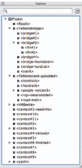
FIG 2.1 Outliner with component tree.
Tip
When one of us made some modifications to a component or a submodel, they saved that component file with a new name before sending it to others. Naming convention was <name of the part>-<explanation>.skp. That way, other people would know in which part of the model modifications had been made and in what way.
With these simple rules about components, you did not have to understand everything that was happening in other parts of the model you had just received. The time of modification of the components was registered with the files themselves; you can clearly see that in the Finder (on the Mac) or File Explorer (on Windows), and that was all the information we needed to know most of the time besides what was there already in their names.
File exchange between the designers in the team was rather intensive throughout various design stages. Sometimes, revised designs were sent out for review several times a day. Of course, this kind of loosely structured system cannot work properly with a large number of people, but for a competition team the size of ours (fewer than ten people), it did the job well.
Step 3: Dividing the Main Project Model into Submodels
Goal: From the main model, create submodels as separate component files with their exact locations registered in the main model.
Input: SketchUp model of the project (including the site).
Tools: SketchUp’s component instances and Outliner.
Even though we tried to keep the project model down to its essentials, it got quite complex in the end with its surroundings and was heavily laden with various components by the time the rendering started.
So, we divided the project file into two separate file types, the main-model file and sub-model files, and generated the latter from the former as component files with their exact locations registered in the main model.
I set up the models as follows:
1. In the main project model, select entities (edges, faces, groups, components, etc.) to be handled as a separate file.
2. To create a component, context-click on the selection, choose Make Component, and the Create Component dialog box appears. Set all parameters to your preferences, but make sure Replace Selection with Component is always checked.
3. After the component is created, context-click the component name in the Outliner > Save As and name the file as <name of the part>-<explanation>.skp. Specify the file location and click Save.
4. Component files can also be saved as separate files via the Component Browser or Edit > Component > Save As menu, but almost always the Outliner is the most convenient and straightforward method.

FIG 2.2 Saving a component as a separate file with context-click.
You now should have submodel files in the folder you specified in the earlier steps. Repeat the steps until the main model is totally divided into comprehensive submodels (components) and no free entities or groups are left in the main model.
Step 4: Editing Component Definitions in Submodels
Goals: Edit entities in submodels and modify component definitions.
Inputs: Component files (submodels) created in the previous step.
Tool: SketchUp’s component instances.
Now you have several submodel files that are generated from the main-model file. Whether it is a piece of furniture, a floor of a building, a whole building, or a city block, try to break the main model completely into comprehensive design units.
Info
When you open one of the submodel files they do not appear to be components; there is no bounding box around the entities. This is because you are already inside the component when they are opened; in other words, changing anything in the submodels means that you are modifying the component definitions.
The submodels created are just like any other components, and there is no special knowledge required to edit these. You can push–pull faces, add details, or apply textures to objects.
Attention
The only restriction of submodel editing is that in submodels, you should not change the general positional relation of objects to their SketchUp axis.
In the same way, you should not redefine SketchUp’s axes and change their original position in submodels. SketchUp’s axes in submodels corresponds to the component’s axes of that component. Its position in the main model is registered by the position of the component’s axes to the original position of main-model SketchUp axes; therefore, changing their positions will force them to be positioned wrongly when reloaded (the next step). On the other hand, changing the axes of the main model does not affect the positions of components within the file.

FIG 2.3 A component axis in the main file and a component axis in the subfile.
Tip
If you need to move SketchUp’s axes in one of the submodels temporarily for modeling reasons, make sure you reset it before saving the file.
The only exception to this rule may be when you are evaluating positional variations of your project, and this is much more easily done if components are modified as a whole, rather than modifying component definitions from inside of them.
I will explain the other modification method (nested components) later.
You also have to be careful not to edit submodel components inside the main model. Any changes you make to these components in the main model will be canceled upon reloading those components. One way to avoid this mistake is by locking these components in the main model: the other way is by working only on submodels (therefore, nobody is editing the main model). If, by mistake, you modify some components and do not want to discard the changes you made, just save that component as a file with a new name before updating.
Step 5: Reloading Submodels into the Main Model
Goal: Put submodels back into their precise locations in the main model.
Inputs: Components (submodels) edited in the previous step.
Tools: SketchUp, Component Instances, and Outliner.
When components are inserted from the Component Browser or imported via File > Import, you have to manually place them where you want them to be in the drawing area. This can easily lead to mistakes and can result in a mess if 20–30 components are constantly being replaced with updated versions.
Reloading is different. Unlike inserted components, reloaded components have their precise position in the main model already registered as their component axis. Unlike inserted components, reloaded components know their precise locations in the new environment because they are registered with the component’s axes. You do not have to place them in the model by reloading them; they automatically go where they should be.
Tips
Another advantage of reloading over insertion is that reloading does not accumulate components in files like Insertion does, and as a result, the file size of the main model depends on the amount of components there are at the moment, rather than the accumulation of all inserted components.
Reload submodel files into the main-model file using the following steps, after some editing. Make sure you save submodel files before reloading them into the main model.
1. In the main model, select a component to be reloaded in the main model window, the Outliner or the Component Browser; unlock it before selecting it if locked.
3. Open. A File dialog box opens. Select the component file you just finished editing. If you want to switch the component to another one, select that file.
4. The component will be reloaded at the right location.

FIG 2.4 Select a component to be reloaded.

FIG 2.5 A component and its instances reloaded.
I would recommend using the Outliner for the above steps, since you will always be aware of the overall file hierarchy of the model, and it even shows the status of hidden or locked components.
Step 6: Editing Submodels as a Whole 1/Proportional Modifications
Goals: Manipulate proportional modifications of component instances.
Inputs: One of submodels created in the previous steps.
Tools: SketchUp, component instances, and the Scale tool.
Our scheme for the competition consisted of eight separate bridges, rather than just the one.
These bridges were formally similar, but slightly different in their lengths. Instead of modeling all eight of them one by one, we used scaled component instances to carry out quick design evaluations.
Tips
The rule of thumb is that modifications done to a component instance as a whole affect only the properties of that particular component instance, whereas modifications done to individual entities within a component (i.e., component definitions) affect all other component instances.
So, if I scale four component instances as a whole to varying degrees, modifications to the component definition of one of them will be proportionally reflected in other component instances.
This means that you can have many variations of the same component (of various sizes and positions), and changes in one of them will affect all other component instances proportionally. Let me explain in models.
1. Create an object and make it a component
2. Create several component instances by duplicating the component
3. Modify them with Scale tool
4. Change the component definition of the original component (i.e., one without modifications)
5. All component instances will be modified proportionally
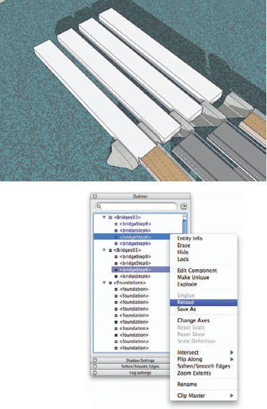
FIG 2.6 A component is duplicated four times.

FIG 2.7 Component instances being modified to various degrees.

FIG 2.8 When one of the component instances is reloaded, all instances change proportionally.
Note that, although all these components in Figures 2.6–2.8 have different lengths and different widths, they are instances of the same component, and updating all of them requires only one of them to be reloaded.
Step 7: Editing Submodels as a Whole 2 (Nesting Technique)/Positional Modifications
Goal: Manipulate positional changes of component instances within another component.
Inputs: A set of component instances created in the previous step.
Tools: SketchUp, the Outliner, nested component instances, the Move and Rotate tools.
Sometimes, we need to evaluate positional changes of a scheme in addition to its formal variations. I briefly touched upon the topic in one of the previous steps as positional changes can also be handled by changing component definitions.
However, if we need to evaluate both options in various combinations, positional options should be handled at different component levels so that we can manipulate forms and positions separately.
Tips
I cannot recommend the use of the Outliner enough, especially when one has to deal with a complex model with multiple nesting of components. The Outliner reduces the need for zooming in and out to search for components or groups to almost none because all components are always visible (even hidden components are visible) in the tree structure of the Outliner, no matter which part of your model is showing on the screen.
So, we will create a nested component from a group of component instances generated in the previous step.
The nested component levels allow us to manipulate positional changes by moving each component instance as a whole, and we can modify the forms of each component instance by its component definition at another level.
1. Make a component from a set of component instances created in the previous step.
2. Context-click > Save As…, and save it with a new file name.
3. Open the saved file, make the positional changes needed, and save it with a new name.
4. Repeat point 3 and create positional options. In this case, I created different moments of the bridges during their sequential open/close cycle.
5. Go back to the main file, context-click the set of bridges > Reload, and switch it with a set in a new position.

FIG 2.9 The saved component file with positional modifications.
FIG 2.10 Select the nesting component in the main file and reload it.

FIG 2.11 The nested component instances change their positions.
Step 8: Evaluating Design Options in Scenes
Goal: Evaluating several design options quickly by reloading different versions of components.
Inputs: Components (submodels) edited in the previous steps.
Tools: SketchUp, component instances, the Scene Manager, and animation export.
We usually assign several design options to different layers and set up scenes so that option A is visible only in scene A and option B is visible only in scene B. We switch back and forth between two scenes to evaluate both options.
However, scenes are also used for other purposes, such as animations, image export, etc. Using the already overloaded function for just one more purpose will only leave us confused and the Scene Manager crowded and too complex.
If submodels are used in place of scenes as a means to switch design options as explained in the last step, scenes and layers need to be set up only once for whatever purpose. Submodel B reloaded in place of submodel A will take over all properties (visibility in scenes, layer-related settings, size modifications, positions of component axes, etc.) of submodel A.
1. Select one bridge from the set in the Outliner, context-click > Reload, and update to another formal option.
2. Context click the set of bridges > Reload and switch it with a set in a new position.
3. Repeat the above two points and try out as many combinations of forms and positions as you need.
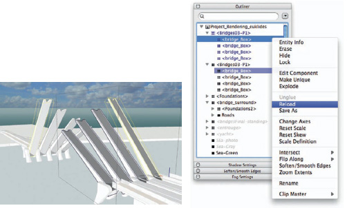
FIG 2.12 Select one bridge from the set in the Outliner, context-click > Reload.

FIG 2.13 A design option appears.
Run through all the scenes (an animation with some delay, but without transitions, might suit this process the best), reload components, and go over all the scenes again.
I think that a series of high-resolution still images usually works best when comparing several design options. In the next step, I will explain the trick of automating batch-image export from SketchUp.

FIG 2.14 After a positional option is reloaded, yet another design option is reloaded.
Step 9: Evaluating Design Options in Still Images/Batch Image Export
Goal: Using the animation export function, automatically export all scenes as image files.
Inputs: The main project model and submodels as design options.
Tools: SketchUp, the Scene Manager, and animation export.
SketchUp does not have batch 2D export, but we can export images one by one via File > Export > 2D graphic. The following procedure automates this process by utilizing SketchUp’s native animation export function.
1. Set up your scenes with all properties set to your preferences. Check Include in Animation, of course.
2. View > Animation > Setting, Uncheck Enable Scene Transitions. Scene Delay has no effect on this operation.
3. Go to File > Export > Animation and choose a file destination and an image format from the options of . jpg, .png, or tiff.
4. Click Options. Image size and Frame rate can be set to whatever you what. Uncheck Loop to Starting Page and Play When Finished.
If you want high-quality images, check Anti-Alias, but this can make the process too time-consuming. Click OK.
5. In the destination folder you specified earlier, you should find rendered image files of all your scenes.
Step 10: Applying DOF Directly to SketchUp Output
Goals: Generate a depthmap from SketchUp using its Fog function, then apply the map to images to give them DOF.
Inputs: A SketchUp model and depthmap.
Tools: SketchUp, Fog, and Adobe Photoshop CS3.

FIG 2.15 Depthmap settings in SketchUp.
About the same time I was taking part in the Te Wero bridge competition, a friend of mine, Lewis Wadsworth, was playing around with SketchUp’s Fog function and managed to find a way to output depth-maps straight from SketchUp.
A depthmap is an image that uses grayscale values to show which areas in our model are closer to us (white) and which are more distant (black). It can be used to give focal blurring to super-crisp, computer-generated images. The resulting images have a DOF closer to what we actually see in reality.
How to create depthmaps in SketchUp:
1. Create a new scene with only two properties checked: Style and Fog, and Shadow Setting. With this scene, you can turn any other scenes into depthmaps instantly. View any scene first and then click this scene tab.
2. Open the Styles Browser to Fog and Shadow Settings. Set parameters as shown in the following:
The important parameters are
Shadow Settings: Dark must be all the way – or nearly all the way – to the right. Check Use Sun for Shading. Fog: Check Display Fog. The right setting for Distance varies from image to image, so play around with sliders. Do not use a Background Color; specify black for it.
Styles Browser: Turn all edges off. Both Front and Back Colors are white in Face Settings; select Display Shaded Using All Same in Styles. In Background Settings, Turn Sky off, and the Ground too if you have no physical ground plane. Set Ground color to white if it is on.
3. Export a depthmap along with a colored image of the same camera setting.
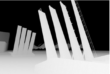
FIG 2.16 The depthmap generated.
How to use depthmaps in image editors:
I am using Photoshop CS3 in this minitutorial, but the same process can be done in many other image editors with a layer function. In the following tutorial, all operations are done in the Layers palette unless otherwise indicated.
1. Open the SketchUp images in Photoshop.
2. In the colored image, double-click the background layer to turn it in to a normal layer.
3. Add a new layer, fill it with white using Edit > Fill, and move it to the bottom of the layer stack.
4. Add a layer mask to the colored image layer: Layer > Layer Mask > Reveal All. Alt + click the layer mask and paste the depthmap into the layer mask created.
5. Select the colored image, then choose Filter > Blur > Lens Blur.
6. In the Lens Blur panel, choose Layer Mask as the source of your depthmap. Play around with the Blur Focal Distance slider to set the depth at which the pixels are in focus.
7. Adding some noise will give the image more air and a realistic feeling. Click OK.
8. Right-click the layer mask and disable it.
If you create a separate line-drawing layer on top of the colored image layer, you have much more control over the look of the image. If you do this turn off all edges from the colored image and switch the line-drawing layer to Multiply and add a layer mask and depthmap as you did for the colored image layer.
The first image is a straight output from SketchUp, and the second is a Photoshopped image with DOF.
When Lewis wrote a depthmap tutorial on one of the SketchUp forums, it was an instant success and the word spread quite fast. Now, you can easily find many depthmap-related tutorials and videos on Internet.

FIG 2.17 Photoshop’s Layers palette.

FIG 2.18 Photoshop’s Lens Blur palette.
Conclusion
In the last 15 years, I have used many CAD packages, both in the offices I worked for and in my own office, to make construction documents, to create a base for physical models, or to make an impressive presentation. However, SketchUp must be the first (and still the only) CAD program I have used for designing, and I believe many other architects use it in the same way.
It doesn’t have B-splines or Bezier-type curves (although some of these are now available through Ruby scripts), and it can be a pain to work on a big project with these shortcomings. However, in spite of this, I have kept using it throughout various design stages of many projects and have so far found no substitute for it.
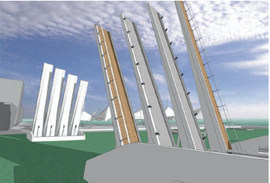
FIG 2.19 Straight output from SketchUp.
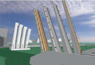
FIG 2.20 SketchUp output with depthmap applied.
What is most interesting about SketchUp for me is that there are always workarounds for its shortcomings. I assumed, in this chapter, that the key must be its simplicity and its pared-down nature. Because of these two characteristics of SketchUp, I have never really encountered in the course of my work that I haven’t been able to get around.
The competition for the Te Wero landmark bridge was the largest project I had taken on with SketchUp; hence, I did not know how well it was going to perform. Although we were not sure about it at the beginning, it did not take long for us to find out how to use components as Xref files. That is the beauty of this piece of software.
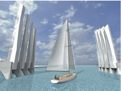
FIG 2.21 Final image.
SketchUp does not draw beautiful curves, nor does it automatically generate extremely complex forms like many CAD packages easily do these days. But it made us work directly on our 3D models and, as a result, kept our communication flowing. Needless to say, that’s the most important thing.
Resources
Software
Adobe Photoshop CS3
Sketchup Plug-ins
Podium by TBD