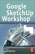
Chapter 10
A Virtual House
After receiving his architectural diploma in 1996, Laurent Brixius set up the ARCH’image practice in 1997 with two other partners who are as passionate as he is about information technology and architecture. The bulk of his work is taken up with the creation of computer-generated perspectives and animations to help architects and property developers communicate with their clients and to promote their own projects. He shares his passion for graphics on the ARCH’image blog, where he posts articles dedicated to computer-generated imagery, several of which focus on SketchUp.
Project: Virtual house for the Belgian Federal Interior Services Ministry.
Tools: SketchUp 7, 3D Studio Max 9, Pano2VR, Photoshop CS, and Notepad2.
Project Context
The Virtual House was a project carried out for the Belgian Federal Department for Interior Affairs. The aim of the project was to make Belgian citizens aware of the means available for protecting and securing their homes against break-ins and fire. The details of the project are available at http://www.vps.fgov.be/virtualhouse.
The ministry first wanted an animation put together that would present, in a sequential fashion, the available means of prevention and security.
Because of the drawbacks associated with this approach (production cost, difficulties with updating it and incorporating future developments, lack of engagement from passive viewers, and a small prospective audience), we proposed improving the visitor experience by using a virtual-reality, interactive tour embedded in a website.
Available on interactive terminals at exhibitions and trade fairs, the Virtual House would allow people to access information at their own pace and according to their personal requirements. Initially intended to go on display at the Batibouw Brussels construction trade fair in the Belgian capital, the project is now available for everybody to use via the Internet at the following address: http://www.besafe.be/virtualhouse.
Technical Context
The project was subject to numerous constraints:
1. Three-month deadline;
2. Limited budget;
3. The innovative nature of the project meant that there was a lack of existing information about how best to implement it.
Therefore, this project needed very tight organization and a clear definition of the tasks to be accomplished by the various people involved in it. In order to gain an overall view of the project, a heuristic chart or “Mind Map” was used. This enabled those taking part to clearly see how the various elements of the project interacted with each other.
A storyboard was then put together to present to the clients, detailing all the different security methods in their contexts. The storyboard was also used to plan a walkthrough. For the modeling, SketchUp Pro was used from the initial sketches to the modeling of the details. The model was then imported into 3D Studio Max for the application of textures, a realistic lighting setup, the setup of still and animated cameras, and the production of 360° VR panoramas and the walkthrough.
For the VR panoramas and the placing of hotspots, QuickTime was used first. However, because of compatibility issues, Flash was subsequently chosen and the placing of hotspots was done with Pano2VR software.
For the production of the website, an improved version of Notepad, Notepad2, was used.
Why Choose SketchUp?
First of all, because it is fun to work with. Its intuitive nature, speed, and ease-of-use have made SketchUp our practice’s tool of choice for quick 3D modeling. It is also used for modeling a large number of detailed projects, images from which go on to be entered into architectural competitions or used in real estate advertising. However, 3D Studio Max is still used for certain elements that would be difficult to model in SketchUp, for example, objects that need to have parametric data input.
The second argument in favor of SketchUp is the lower number of faces that are produced when modeling, something that can greatly reduce the calculation time for a rendered image.
Third is SketchUp’s ability to communicate a project clearly and unambiguously, either with a client or with those involved in the construction process. The fact that the client can understand the project immediately means that decisions are made more quickly.
Techniques Used
Many users make great use of layers when they work with SketchUp; however, SketchUp’s layers do not work in the same way as those in other CAD programs. In SketchUp, the following approach should be employed: All faces and edges should be drawn on Layer0. Then, they should be either grouped or made into components and then assigned to a particular layer. Only groups or components should ever be placed on a layer other than Layer0. Layers are used for project organization and to simplify the workspace by only showing the elements being worked on at any given moment.
For this project, two Ruby plug-in scripts were used:
• Push–Pull Z: This plug-in saves an enormous amount of time when modeling roofs. The roof pitches are first modeled as simple faces. Then the faces that are to be push-pulled (i.e., given thickness) are selected. The plug-in is then chosen from the Plug-Ins menu, and a dialog box appears. The desired thickness is entered here, OK is clicked, and the roof pitches will be extruded in the Z axis (not perpendicular to the surface, as the standard Push–Pull tool does). Any other modeling can be carried out using SketchUp’s own Push–Pull tool.
• Reverse Faces: After choosing it from the Plug-Ins menu, this Ruby script allows you to change the orientation of a face by using a simple left-click. With the default material, the face is either beige (exterior) or blue-gray (interior). Most rendering engines will not “see” a face if its interior is pointing outwards (if it is “flipped”). If a face in the SketchUp model is flipped, it will simply be ignored during the render calculation, and your model will appear to be full of “holes.”
Tip
If you have applied materials to faces, you cannot tell whether they have been flipped or not. If this is the case, change the Face Styles display mode to Monochrome to see all faces in the default color. You will then be able to see each face’s orientation and to change any flipped faces using the Reverse Faces plug-in.
New Approaches
If you have a well-organized 3D model, you can avoid making lots of errors and save many hours of work. One of the most important things that you can do is to clearly name all the elements that make up your scene. Our practice has developed a naming system that allows us to very rapidly identify any architectural element. To avoid having to rename each element when it is imported into 3D Studio Max, a three-stage preparation method is used:
1. A materials library is created in which each material corresponds to the layers that will be used for export. Our practice has a ready-made library of materials, and we add new ones as necessary.
2. The materials are then added to the different elements in the SketchUp model using the Paint Bucket tool. These materials have names such as 41 brick, 31 framing, 37 facia, 47 roofing, etc.
3. Before export, the plug-in Layer by Material is run. As its name suggests, this creates a layer for each type of material used in the model and moves all elements that have that material applied to the relevant layer.
The model is now ready to be exported in DWG or 3DS format.
Tip
Sometimes, groups and components may need to be exploded before using this plug-in. If this needs to be done, the original model should be saved and a copy should be made. This will conserve the working organization of the original model. In the copy, all the groups and components should then be exploded. This process can be automated by using the Bomb plug-in by Rick Wilson.
Stage 1: Draw Up a Schedule
Objectives: To draw up a list of key project stages and a list of fire protection and security measures to be shown in the Virtual House. To define the extent of the project and the submission dates for the intermediate stages. To create a storyboard showing each element in place.
Data: Documents provided by the client and information collected during initial client meetings.
Tools: Pencil and paper; copies of storyboard pages; and Mind Mapping software.
As essential element for the smooth running of the project, the schedule allows you to clearly define the expectations of your clients and what you need to deliver.
Using Mind Maps gave a global overview of the project, enabling a clear visualization of the complex interactions between the different webpages that need to be created.
The creation of a storyboard meant that certain views could be agreed upon with the client. The level of detail of certain elements within the Virtual House could also be set at this stage, according to their distance from the camera in each storyboard view.
Stage 2: Hand Sketches of the House
Objective: To clarify the volumes in the spaces that need to be created.
Data: Data obtained in the previous stage.
Tools: Pencil, eraser, and paper.
Even if SketchUp is an extremely intuitive sketching tool, it is often best to start off with hand drawings.
Stage 3: 3D Roughs of the House in SketchUp
Objective: To create models that would aid in client discussions and validation with clients before more detailed 3D modeling takes place.
Data: Hand sketches, storyboard showing key elements, and Mind Map.
Tool: SketchUp Pro.
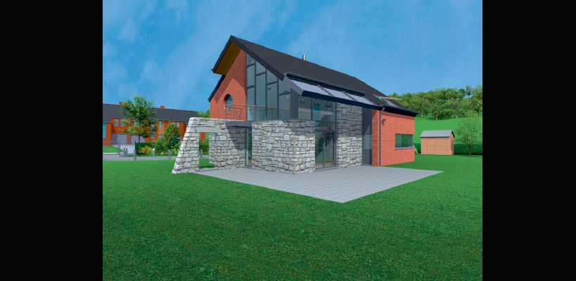
Modeling starts off with the exterior envelope of the house: The outline of the house is drawn with the Line tool, then the Push–Pull tool is used to extrude the newly created face, forming a volume. The volume is then further sculpted using guides and the Line and Push–Pull tools.
Screenshots of this first stage were then sent to the client for approval, and the date for a consultation meeting was fixed.
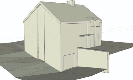
FIG 10.1 3D sketch.
At the same time, modeling of the immediate surroundings of the house in SketchUp was started. In order to speed up the OpenGL display, the house and the surroundings were initially modeled in separate files. Modeling the surrounding wooded hills would be carried out in 3D Studio Max at a later stage.
Stage 4: Consultation Meeting with the Client
Objective: To evaluate the suitability of the 3D sketch in terms of the methods of fire prevention and household security to be presented. Determine what modifications need to be made to the project.
Data: Visualization of the 3D model in SketchUp and print images.
Tool: SketchUp Pro.
At the meeting, the 3D model was viewed from all angles within SketchUp using the Orbit tool. A list of modifications was drawn up.
Stage 5: New 3D Rough and Client Validation
Objective: Adapting the 3D model according to the constraints defined during the consultation meeting.
Data: Notes from the meeting and annotated images from the client meeting.
Tool: SketchUp Pro.
A new model was made, taking into account remarks made during the client meeting. The project was then tweaked to better respond to the client’s demands.
At the same time, a schematic development of the interior of the house was carried out, based upon the new exterior volume.

FIG 10.2 New 3D sketch.
After viewing the amended model, the client gave their approval, which meant that the model could be further detailed.
Stage 6: Detailed 3D Modeling in SketchUp
Objective: To create a detailed 3D model that would be used as the basis for computer-generated renders.
Data: 3D sketch approved by the client.
Tool: SketchUp Pro.
After an inconclusive attempt to separately model the interior and exterior of the house, the modeling was started anew. The client-approved 3D rough was loaded into SketchUp and the whole thing was grouped and placed onto its own layer. This model would serve as a reference for any subsequent modeling and its visibility could be easily turn on and off by unticking the Visibility checkbox on the layer.
Modeling was started by drawing the outline of the house using the Line tool. Once this outline was complete, the wall thicknesses were added by using the Offset tool.

FIG 10.3 Tracing the outline.
First, the walls and interior partitions were modeled, along with the stairwell. To make. subsequent modeling work easier, materials from the ‘Layers’ library were assigned to all the different materials in the model: One for the stone wall work, another for brickwork, another for stud partitions, etc.
With this stitch over, the walls and partitions were extruded using the Push–Pull tool to a height a yard or two greater than the ridgeline of the roof.
Next, the two roof pitches were modeled by simply drawing two lines and then rotating them to the correct pitch using SketchUp’s Rotation tool. These lines were then Copy-Moved so that the resulting roof pitch would completely overlap the house model. The ends of the lines were then joined using the Line tool, which automatically created the faces.
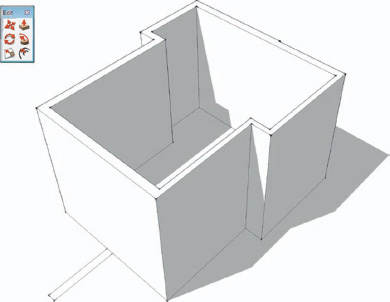
FIG 10.4 Modeling the walls.
In this stage, the extruded walls and partitions were selected, as well as the two faces that defined the roof pitch. Since SketchUp does not have any native Boolean tools, the Intersect with Selection command was used (right-click and choose Intersect > Intersect with Selection from the contextual menu). This resulted in cuts being made to the model that correspond to the roof pitch and to the gable ends. The next step is to select all the geometry above the roof pitches and to erase them using the Delete key.

FIG 10.5 Cutting the walls using the roof pitches.

FIG 10.6 Cutting the walls using the roof pitches.
Tip
Choosing the Intersect with Selection option instead of the straight Intersect option places less stress on the processor and produces a quicker result.
To produce the roof thickness, the Push–Pull tool was used on each of the pitches. Guidelines were used to locate the precise intersection of the ridge line. The upper edge of a single pitch was selected, then, using the Move tool, the end point of the edge (look for the green Endpoint snap dot) was moved until it snapped to the intersection of the guidelines.

FIG 10.7 Push-pulling the roof pitches directly in the Z axis.
Tip
A quicker and easier solution would be to extrude the roof pitches directly up in the Z axis, something that is not possible with SketchUp’s own Push–Pull tool. Luckily, Didier Bur has created a plug-in, Push–Pull Z, that allows you to do just that. See under section “Techniques Used.”
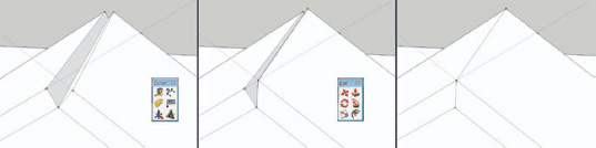
FIG 10.8 Closing the ridgeline using the Move tool with guidelines.
With the basic roof shape completed, the fascias and soffits were then modeled, as well as the garden wall and the sunscreen canopy. Next followed the modeling of the window and door openings, simply by drawing them onto the exterior surfaces and push-pulling them through. For the circular window, the Circle tool was used, but with its number of sides set to 96 to avoid any jagged edges in the final renders.
Tip
By default, circles are made up of only 24 segments and arcs of 12 segments, which is insufficient for getting a smooth outline. This value can be increased either in the VCB before you start drawing or at any time from the Entity Info palette. Once a face is extruded, the number of circles or arc segments cannot be changed. Arc segments can, however, be changed if the arc is part of a face.
The door and window frames were modeled independently. Each frame was created as a component in order to make any future modifications easier.
The chimney pipe was modeled simply by drawing a circle of the required diameter and extruding it. The conical end was achieved by extruding the upper face using the Push–Pull tool holding down the Alt/Option key (Mac) or the Ctrl key (Windows). This creates a new pipe segment that can be selected separately. The conical end was achieved by selecting the upper surface of the new segment and doing a uniform X, Y scale – about the center (hold down the Alt/Option key on the Mac or the Ctrl key in Windows).

FIG 10.9 Modeling the canopy and the garden wall.

FIG 10.10 The window openings push-pulled through.

FIG 10.11 The door and window frames modeled.

FIG 10.12 Creating the window frame components.
Stage 7: Preparing and Exporting the Model from SketchUp
Just before exporting, the Layer by Material plug-in was run. This creates a number of layers corresponding to the number of different materials in your model and then places all elements that have the same material into the corresponding layer (see under section “New Approaches”).
The model can now be exported to DWG format. To do this, in the Menu Bar, go to File > Export > 3D Model… and then choose AutoCAD DWG from the Export Type: drop-down menu. In the Options… sub-dialog, make sure that only Export: Faces is ticked. This will avoid exporting unwanted geometry like stray lines, etc.
For the balustrade, a separate SketchUp file was created by copying only the edges and pasting them in a new file using the Paste in place command. For this file, the export options were set to Edges only. These could then be used as paths for the Lofts or Sweep commands, or simply be given parametric thickness.
Tip
SketchUp remembers the last export options that were used. Always remember to check your export options before your next export operation.
Stage 8: Detailing the Model in 3D Studio Max
Objective: To continue modeling the house and its surroundings in more detail.
Data: Model exported from the SketchUp in DWG format.
Tool: 3D Studio Max.
The DWG files were imported into 3D Studio Max, choosing the AutoCAD Drawing import option.
Tip
If you need to work in metric, remember that SketchUp7 exports files with metric units as if they were inches (this was corrected in 7.1). You can correct this if you have a copy of AutoCAD: enter “_units” in the command line, indicating the correct units in place of “Inches.” If you do not have AutoCAD, the AutoCAD Drawing format allows you to configure the imported file units manually and so this should be your preferred export format.
In order to keep all modeling options open, only the edges that correspond to the central axis of the balustrade were imported. They were converted into editable splines and then the edges of the handrail were attached along with those for the horizontal elements and the balusters. Display in Viewport was activated to show the thickness of the splines. Next, a thickness was given to each element of the balustrade. The Display in Render option was then chosen to make the baluster elements visible at render time.
A wing-shaped element of the brise-soleil was created from an ellipse that was in turn created by deforming a circle. The Extrude modifier was then applied to this profile, and the element copied using the Instance option. Once each pane was in place, they were selected and the orientation was varied using the Rotation tool, set to Use Pivot Center.
The hedges in the garden were created by extruding a profile along a path using the Loft tool, then applying an Edit Poly modifier to the resulting object. The resulting mesh was then edited to give a more natural look. Using the Loft tool has many advantages over a mesh created in SketchUp, then imported into 3D Studio Max. The first advantage is the ability to apply mapping coordinates that follow the extrusion path of the loft. The second is the ability to vary the profile of the hedge after the loft has been created, by choosing the Instance option when choosing the spline profile. This proved to be extremely useful since the height of the hedge needed to be modified later.
To model the surrounding hills, highly subdivided planes were used. The Soft Selection option was chosen in order to produce a gradual and homogeneous deformation when the vertices corresponding to the summits of the hills were displaced.
Stage 9: Apply Materials to the Detailed Model
Objective: To get the materials looking as realistic as possible for the final render.
Data: Materials Library and photos of materials.
Tool: 3D Studio Max.
Since all the elements in the scene are named according to scheme based on architectural elements, it is simple to select each type of element by name, then to apply the corresponding material. Mapping coordinates are then applied to give the correct scale to the different textures.
Stage 10: Setting Up the Lighting Using “Fakiosity”
Objective: To produce a photorealistic render extremely quickly, without resorting to a global illumination rendering engine.
Data: Textured 3D model.
Tool: 3D Studio Max.
Lighting is the most important factor in obtaining a high-quality rendering. Today’s photorealistic rendering engines can produce images that are practically indistinguishable from photos, but at the cost of extremely long rendering times. Since time was short, the “fakiosity” lighting technique was chosen, which simulates the indirect lighting received from surfaces by using attenuated lights.
For the external lighting, an array of spotlights was chosen that would simulate the lighting from the sky component. A directional spot was also added to simulate the sun. These “sky dome” spots were given a slight blue hue and were set to project very soft shadows using shadow mapping (size: 512, sample range: 40). The directional “sun” spotlight (parallel rays) used more sharp-edged, raytraced shadows. In order to reduce the rendering time further, none of the glasswork was set to cast shadows (right-click on an object and under Object Properties, uncheck Cast Shadows).
Stage 11: Camera Placement
Objective: To produce renders that would clearly show the position of the VR hotspots.
Data: A list of the hotspots to be shown.
Tool: 3D Studio Max.
This stage is extremely simple: The essential thing to keep in mind is to have the hotspot exactly at the same height as the camera to avoid any parallax effects.
Stage 12: Positioning the Hotspots and the Direction Arrows
Objective: To increase the visibility of the hotspots in the VR panoramas.
Data: List of hotspots to be shown.
Tool: 3D Studio Max.
The images that are used to create VR panoramas are highly distorted. Therefore, the hotspots and direction arrows could not be added in later in Photoshop because they would have to show exactly the same distortion as the VR panorama image. It was therefore decided to model these elements directly in 3D and to place them around each camera in the position that they should be in the final panorama (see Figure 10.13). To make things easier, each of these 3D elements had the LookAtMe constraint applied. This means that they would always face square to the camera, whatever be the camera’s position. The Planes Look modifier was also used: This is a part of the Itoosoft Forest Pro plug-in covered in the following stage.

FIG 10.13 Placing the 3D hotspots and direction arrows.
Stage 13: Adding the Vegetation
Objective: To increase the realism of the project. The height of the vegetation also needed to be shown.
Data: Photos of trees and plants.
Tools: 3D Studio Max and Itoosoft Forest Pro plug-in.
Adding true 3D vegetation greatly increases rendering time. It was therefore decided to use simple rectangular polygons oriented toward the camera. These polygons had a tree or bush texture applied to them. These textures also had an alpha channel applied to them in the material’s Opacity Map field. This knocked out the background of the texture, leaving only the vegetation on a transparent background.
Tip
In view of the number of trees needed for the garden and for the surrounding hills, we had to fall back on Itoosoft’s Forest Pro plug-in. This plants vertical rectangular faces that are automatically oriented toward the current camera and provides an enormous time saving, especially given the number of different cameras used. The plantation density is provided by a black-and-white texture map, where each white pixel represents the position of a tree or plant.

FIG 10.14 Placing vegetation using Forest Pro.
Stage 14: Rendering the VR Panoramas
Objective: To produce the panoramas for the virtual interactive visit.
Data: Illuminated and textured 3D scene.
Tool: 3D Studio Max.
The Panorama Exporter tool was used, which automatically renders and composites the six different views necessary to make a VR panorama image. It is extremely simple to use, and the user needs only to specify the resolution of the final image (the aspect ratio is always 2:1). The choice of image formats depends upon the software used to produce the 360° interactive views. For Pano2VR, the PNG format is preferred.
As explained in stage 12, the rendered VR panorama is extremely distorted (see Figure 10.14). This is why the direction arrows and hotspots were calculated in 3D.
Stage 15: Putting the Virtual Interactive Visit Together
Objective: To produce and link the panoramic views in flash format.
Data: Panoramic images in PNG format and list of webpages to be linked.
Tool: Pano2VR.

FIG 10.15 VR panorama render.
Each panoramic image was imported into the Pano2VR software where the setup of the initial viewpoint and the hotspots can be configured. The clickable fields are either a question mark (leading to a page of advice on either fire or break-in protection) or a direction arrow (brings up a webpage with a new viewpoint).

FIG 10.16 Putting the virtual visits together using Pano2VR.
After an initial user test, it was decided to control the flow of the visit by placing only one direction arrow in any exterior panoramas. This makes sure that the visitor does not end up facing in the wrong direction, unable to gain access to the Virtual House.
In order that the visitor does not get lost in the Virtual House, an interactive plan of the current floor was displayed below the panoramic view. A colored dot indicated the visitor’s current position. Clicking on the other buttons enables direct access to the corresponding viewpoint. All the viewpoints were also accessible from a webpage that displayed them, all sorted according to their environment (exterior, interior first floor, interior second story, etc.).
Stage 16: Creating the Website
Objective: To produce a standards-compliant website.
Data: Text in French and Flemish and photographs and illustrations from the Virtual House.
Tools: Photoshop and Notepad2.
A mock-up of the website was first put together in Photoshop. The various elements of the visual design were then cropped and exported in JPEG format with a compression ratio suitable for the web.
The site structure was constructed in XHTML 1.0 Strict, and the visual aspects were programmed using CSS.
Unlike certain web designers who use website creation software like Adobe Dreamweaver, our practice prefers to work directly on the code in a text editor. To this end, Notepad2 was used, since it formats and indents XHTML and CSS code.
Some parts of the site were developed in JavaScript, noticeably the dropdown menu, something that was indispensable given the number of pages that needed to be accessed. It was also used to embed the Flash animations.

FIG 10.17 The website in use.
Conclusion
Choosing SketchUp was a wise move in view of the extremely tight deadlines for a project in which there was a lot of ground to cover. SketchUp allowed us to
• communicate effectively with the client and accelerate the decision-making process;
• evaluate concepts in real time;
• put together the rough models and the final, detailed one;
• reduce the number of polygons to a minimum, and therefore
• reduce the rendering time for each image, and therefore
• put together an animation extremely quickly.
Our initial choice of SketchUp proved to be sound: The entire project could have been modeled in 3D Studio Max, but the process would have been less intuitive and more work would have been needed to advance each stage of the project.
The Virtual House project has been evolving since the end of 2005, and today, it is in its fifth iteration, with the addition of animations showing the implementation of the prevention and protection methods.
This first experience with interactive virtual reality allowed us to offer a more groundbreaking service. This was the first commission for the Federal Department for Interior Affairs, and the client’s satisfaction has brought with it numerous other commissions, including some in areas outside of architecture. We can say without fear of contradiction that this project has greatly expanded our practice’s sphere of activity and has actively promoted our professional activities.
Resources
Software
Autodesk 3D Studio Max 2010 – Retails for $3,495.
Garden Gnome Software Pano2VR – prices start from ∊59 (about $84), excluding sales tax. Available at http://gardengnomesoftware.com/pano2vr_license.php.
Adobe Photoshop CS5 – price around ∊840, excluding sales tax.
SketchUp Plug-ins
Push–Pull Z by Didier Bur. Available at http://www.crai.archi.fr/RubyLibraryDepot/Ruby/fr_push_pull_z.rb.
Reverse Faces tool by Todd Burch. Available at http://www.smustard.com/script/ReverseFaces.
Layer by Material by Tim Bertschinger. Available at http://www.crai.archi.fr/RubyLibraryDepot/Ruby/fr_layerbymaterial.rb.
3D Studio Max Plug-in
ItooSoft Forest Pro 3 – ∊250 (about $350), excluding sales tax. Available at http://www.itoosoft.com/english/menu.php?id=forest_register.