
OVERVIEW 3
More Tips and Tricks
Smoothing Arcs, Circles, and Curved Polylines Imported into SketchUp
Any arcs, circles, and polylines imported into SketchUp are assigned SketchUp’s own default number of segments, namely 12 for arcs and 24 for circles. These numbers may be OK for a schematic model, but you will need smoother curves for more detailed modeling. This is not a problem for arcs and circles: You can still modify their number of segments by selecting them and entering the desired number of segments in the Entity Info palette. It is too late for polylines, though: SketchUp sees these as a sequence of straight segments.
The only solution is to decompose your polylines in the program that generated them before you export to SketchUp. Do this on a copy of the file, though: You may still want to edit your polylines in the original file later.
It is rarely a good idea to start modeling directly on the elements of an imported file in SketchUp: Modeling errors crop up frequently (lines whose end points do not touch, unwanted elements that clutter up your model, etc.).
Copy–Paste Referencing a Precise Point in Your Model
Are you trying to perform a Copy–Paste in SketchUp, but you just cannot place the copy in relation to a precise reference point?
Most often (but not always), SketchUp uses the bottom left point of the selection as a reference point. So, what do you do? You simply have to draw a line from your object, whose one end touches the reference point. Select this line as well when you select your object for copying (or you could draw it inside the group or component). Once you are in the file where you want to paste your selection, either hit Ctrl+V (Cmd/Apple+V) or, from the Menu Bar, select Edit > Paste. The objects that you have just pasted will remain selected. Now, you just need to move the end of your reference line onto the reference point in the file, and the job is done. Do not forget to delete this line if you do not need it anymore.
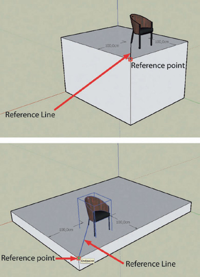
OVERVIEW FIG 3.1 Using reference lines to move imported elements to their position in the model.

OVERVIEW FIG 3.2 Alignment on an inclined plane.

OVERVIEW FIG 3.3 Defining a rectangular reference base.
Aligning Objects to Nonorthogonal Planes
If you have ever tried to place a component on a nonorthogonal plane, then you have probably been dreaming that someone would invent a plug-in like fr_align_tool.rb. Your component will be placed in just six clicks, without you having to jump through any hoops. You have just got to try it!
How to Use It?
1. Start by selecting the elements that you want to align – it is easier if you group them or turn them into a component.
2. Right-click (Ctrl-click on a Mac) and choose Align from the contextual menu.
3. Click on a point that will define the movement origin of your selection. Click on a point on the X axis and then click on a point on the Y axis. This defines the plane of origin of what you want to align.
4. Choose three points that will define the surface that you want to align to. And that’s it.
You may have to move your selection to get it precisely where you want on the surface, but the hard work is done.
What Do I Do if My Component Does Not Have Any Visible Angles or if It Is Not Orthogonal?
It may be that your component is made completely out of curved elements and has no well-defined axis to select. In this case, the simplest solution is to draw a rectangular element that encompasses the base of your component and temporarily group it.
Tip
Another method is to group all the elements that you want to align into a single component. When you create the component, choose the option Any in the Alignment drop-down menu. You could also choose the option to Set Component Axes if the standard alignments do not suit you. Now, erase the component from your scene, and reinsert it from the Components Browser. Thanks to the Any option, your component will align itself to any faces that your cursor moves over.
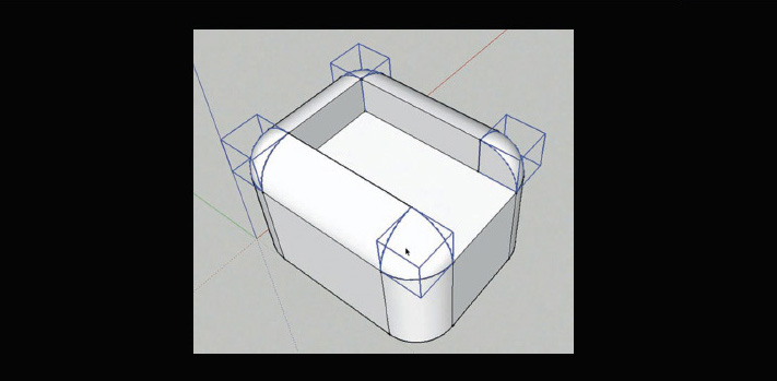
Rounding Edges
In real life, very few buildings or objects have true sharp corners. Beveling or softening the edges of a 3D model will, therefore, add realism to a scene. Additionally, these rounded edges produce a specular effect which heightens the realism of your renders. Unfortunately, SketchUp does not have a tool for beveling one or more edges, although…
As is often the case, it is possible to use a simple SketchUp tool to carry out a complex operation. To get a beveled or chamfered edge (the equivalent of the Adjust command in AutoCAD) in SketchUp, start by drawing a line or an arc on the surface that you want to chamfer or bevel. Now, use the Push–Pull tool to remove a part of the solid and obtain a rounded or chamfered edge.
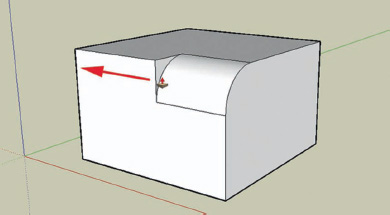
OVERVIEW FIG 3.4 Beveling with Push–Pull.
If you need to chamfer or bevel several contiguous edges (if you are modeling a piece of furniture, for example), then use the Follow Me tool.
Tip
If you need to round or chamfer corners frequently, you should consider creating reusable bevels or chamfers that you can save to the component library. Once they are inserted into your model, you can scale them to adapt them to your needs.

OVERVIEW FIG 3.5 Bevel multiple angles using the Follow Me tool.

OVERVIEW FIG 3.6 Reuse beveled edges as components.
Cutting One Volume with Another – Boolean Operations in SketchUp?
You know that SketchUp is a surface modeler, and that is one of the things that prevents it from being able to carry out true Boolean operations – subtraction, union, or intersection of solids. But there is no need to panic as an alternative solution exists: You just need to use the Intersection operation. Select the volumes that you want to union, subtract, etc.; right-click (Ctrl-click on a Mac); and choose Intersection from the contextual menu. A further two options are available in a fly-out menu: Intersect with Model or Intersect Selected. This operation calculates the edges that constitute the intersection between the different selected faces and cuts them at this junction. All you then need to do is to erase the unwanted faces.
In order to keep the number of edges and faces in your model down, you should use Intersect Selected in preference to Intersect with Model. The former has the advantage of being faster because SketchUp (and your CPU) has to deal with considerably fewer elements.
The paid-for plug-in BoolTools by Dale Martens allows you to carry out Boolean operations on groups and components.
Extract an Image From a Materials File (.skm)
Would you like to reuse or modify a texture that is used for a SketchUp material but do not have the original bitmap? It really could not be simpler. SketchUp’s .skm files are, in fact, nothing more than ZIP files. Change the extension .skm to .zip and you can now open the archive directly, either in your Windows File Manager or in the Mac Finder, or even with a decompression utility if you have to. The images can be found in the / ref. subdirectory.
Filling-In Section Cuts
SketchUp’s section plane tool is really useful, but the resulting section cuts, showing the interior of the cut volumes, does not look particularly nice. Luckily there is a plug-in, Section-Cut Face, developed by TIG, that automatically generates filled-in outlines for the section cuts. Once the plug-in is installed, restart SketchUp, select your section plane, right-click (Ctrl-click on a Mac), and select Create Section Faces in the contextual menu.

OVERVIEW FIG 3.7 Simulate a Boolean operation with the Intersection tool.
Resources
Scripts
Plugin fr_align_tool.rb, by Didier Bur. Available at http://www.crai.archi.fr/RubyLibraryDepot/Ruby/FR_edi_page.htm.
Plugin booltools.rb, by Dale Martens. Available at www.smustard.com.
Plugin fr_SectionCutFace.rb, by TIG. Available at http://www.crai.archi.fr/RubyLibraryDepot/Ruby/FR_arc_page.htm.