
Chapter 7

Process Plant Design
A graduate from the Massachusetts Institute of Technology with over 25 years of experience in process plant design and construction, Mitchel Stangl came across SketchUp in 2001 as an intuitive modeling program. Since 2003, he has used SketchUp exclusively to model process plant projects. Mitchel has spoken on working with large models and using AutoCAD with SketchUp models at the 2005 and 2008 SketchUp user group meetings.
Mitchel Stangl and Stangl Associates use SketchUp to design industrial processes. These include metal recovery systems, material handling, and mineral-processing expansions and upgrades. Stangl Associates utilize SketchUp through the entire design process. The project facility is modeled in the initial phase of all projects. This allows the design team to understand, visualize, and determine the physical constraints of projects. The model is then used as a communication and assessment tool to develop options based on client needs. Once feedback is obtained and an agreement is reached, the design process is finalized and project equipment is selected. Using the SketchUp model and LayOut, construction documents are created to convey the project to contractors for construction.
Project : The project aims to illustrate the SketchUp and LayOut techniques used by Mitchel Stangl and Stangl Associates in designing industrial process plant design projects. These projects range from basic studies to detailed construction designs.
Tools: SketchUp 7.1, LayOut 2.1, scanned historic drawings (both hand-drawn and CAD drawings), digital photographs, and field surveys.
Final Output: Project model and construction drawings.
Project Context
My company works for corporations with patented and proprietary processes. Most of our work involves designing new and upgraded processes within existing facilities. This study focuses on the general design process for these types of projects, and not a particular project.
Techniques Utilized
We model to understand, visualize, and determine the physical constraints of our projects. Modeling is our essential technique and practice. We also do calculations, analysis, and other common engineering techniques as are required to design a process plant facility.
Most of our projects require a great amount of detail, which causes our SketchUp models to become very large. In response to occurrence of such large models and complexity, we have developed a technique to work with them. These methods are applicable when working with any large SketchUp model.
Because of our commitment to 3D design, we also use LayOut to create our construction documents. LayOut allows us to use 3D models as the basis for our drawings. It means that we never abandon these models. We never go to 2D drawings, or export from the SketchUp files. The 3D models are the backbone of the LayOut file and, therefore, our drawings. We do create 2D drawings, but they are really just projections of the 3D model.
New Approaches
In our industry, 2D design is still the predominant design method or tool. There are a small percentage of firms that use solid modeling programs. These programs are very complex, require intensive training, and are expensive. Our innovation has been to work in three dimensions and adapt a simple and intuitive software, that is, SketchUp/LayOut.
We became committed to the use of 3D software and eventually 3D design techniques 15 years ago. SketchUp became a part of our workflow in 2001. In 2004, it became our only 3D modeling tool. It has given us an advantage in ease of use and training. SketchUp is no longer a part of our focus; it is an integral part of our work.
SketchUp was and is considered by many people to be just a conceptual design tool. We know this is not true. It can be used for detailed design. We use it every day for detailed design. In our industry, this use of SketchUp is original.
LayOut is not a well-understood program. Use of LayOut greatly changes the uses and benefits of all SketchUp models. It allows these models to be used in the creation of construction documents. For most design professionals, the two programs can replace existing CAD use.
Step 1: Modeling the Existing Conditions
Goal: To create a model of the existing conditions or facility.
Inputs: 2D drawings of existing facility in CAD or scans, photographs, and site survey information.
Tool: SketchUp 7.1.
We start with the creation of a model of the existing conditions/facility. This facility consists of concrete/steel structures and process equipment. Generally, there are drawings of original structures and equipment, and major additions. These never form an up-to-date set of drawings that reflects the true state of a facility. We gather paper drawings, CAD files, electronic scans of the original drawing, and photograph and field survey the existing facilities.
From the existing drawings, files, and field measurements, we produce a model of existing conditions. We use many different techniques to create this model, depending on the type, quality, and complexity of the information and objects to be modeled. In general, we create the existing plant model by modeling the gathered information, which is imported into a SketchUp file. We import both CAD files and scanned drawings. These imports are used as references for creating the model. The most common use of these imports is just to provide dimensional references in one plane. We also construct virtual 3D drawings models from the 2D drawings set at the appropriate elevations and locations. Then we can model more complicated structures and equipment.
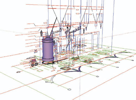
FIG 7.1 Arranging 2D imported CAD files in 3D space to create equipment models.
Photographs are also used for reference and in the SketchUp Photomatch tool. We have found the Photomatch tool to be a very powerful tool in modeling large existing structures and equipment. This is especially true for exterior shots of large buildings or for buildings that cannot be easily measured.
The existing facility model is our starting point for the new project. Since SketchUp is so intuitive, modeling using this tool feels more like constructing. The act of modeling an existing facility enhances our understanding of the facility. This is a very powerful step in our design process; as we create the model, we create a greater understanding and familiarity of the spatial constraints of the site and project.

FIG 7.2 Photographic view of an existing facility.

FIG 7.3 Model view of an existing facility.
Tips about modeling using CAD and image files:
1. It is usually easier and quicker to group the imported file and CAD or image, and model it. Using the imported geometry is more difficult because often the geometry is not always complete or accurate. Therefore SketchUp has problems recognizing CAD line work.
2. In the Style Dialog, set the edge color to “by axis,” so that you can see if the lines are square to an axis. This is a great reference to ensure that you are “tracing” the lines correctly.
3. Save these development files (we suggest naming them as “Devo-” and saving them in a special folder) with the CAD files or images in place. This file organization allows you to quickly check your work against the original basis when needed.
Tips for complex models
1. Large models are just collections of many small models. Everything in your model should be a group or a component. This is the most effective way to start organizing a SketchUp model, in particular, large models.
2. Large file size and high polygon counts will slow the model response, increase saving times, and, most importantly, limit the extent of your model. So, minimize the polygon count whenever possible. For example, not every circle needs 24 sides. For example, our tanks of 10 m diameter should have 24 sides or more, whereas a 15 cm pipe should have eight sides. When you build your models, try and limit the curvature of objects as much as possible to reduce the number of faces. Another example for many projects is steel beams. Use steel beams having rectangular shapes and not rounded corners. You can check how big your model is by going to Window > Model Info > Statistics. Make sure the Show Nested Components option is checked. This will tell you how many faces and edges there are in your model.
3. Organize your model from the start. Use layers to organize your model and to control visibility. Think about creating a system for naming your layers. For example, you could make all the structure layers start with “S-___,” all the architectural layers with “A-__,” and so on. We like to use layers starting with “1-___” for all new work.
4. Use layers and groups/components to nest geometry. You can and should make groups/components out of smaller components. With the layers, you can create a hierarchy of geometry or nested layers.
In this example, the numerals 1, 2, 3 are individual components and are grouped together as a component called Numbers. So, you can turn off or hide all the numbers by unchecking visibility of the “0-number” layer, or you can switch off each individual number. This is same with the letters too. Also note that the Nesting layers have a zero leading their names. That way they are at the top of the list. Although this is not important when there are only nine layers, this does matter when you have 500 layers.
The Entity Info dialog box is also shown. It gives you the component and layer of the selection; in this example, the component is Numbers and the layer is “0-numbers.” Also the Outliner dialog box shows the structure of the groups/components. You can find any group or component in the model from the Outliner. There are many options in the Outliner; just right-click a group/component to see the options.

FIG 7.4 Simplified versus standard steel beam model.

FIG 7.5 Nested layers/geometry.
Tip
We have created a full library of 3D structural steel shapes. If these are all created with uniform length and components axis, then substituting one shape for another is straightforward using the component context menu or the Component browser. We recently created dynamic components that have all steel dimensions embedded in them.
Step 2: Designing and Modeling New Process Plant Options
Goals: To create a process flow diagram (PFD) and conceptual model of the new process; to obtain client approval of the proposed design.
Inputs: Preliminary process flow diagram, the existing facility model developed in step 1, and basic knowledge of the proposed process equipment.
Tools: SketchUp 7.1 and GoToMeeting (web conferencing).
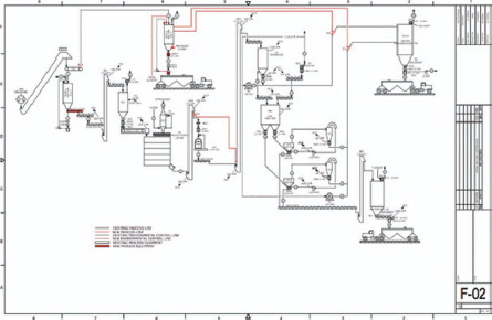
FIG 7.6 Process flow diagram created in LayOut.
Based on client input, review, and discussion, preliminary PFDs are created. Here, we discuss the creation of PFDs with LayOut 2.1.
We then model the process with SketchUp. SketchUp allows us to quickly model the preliminary process based on the PFD. As the model is created, process flow changes to accommodate the physical constraints of the project, which are realized while modeling the process. The PFD development and modeling are very interactive processes. While working simultaneously on the process and the model, design options quickly become apparent.
In traditional engineering projects, PFDs are developed along with simplistic 2D general arrangement drawings. The drawings are time consuming to create. In the traditional design process, this is an essential step. These 2D drawings are reviewed or marked up by the client, and returned to the engineer for approval or additional development. The 3D SketchUp models and web conferencing have eliminated this step for us.
Now, we review a model of the project. This takes much less time than creating 2D drawings. Usually, the review is done online in a web conference. The SketchUp model is reviewed, including all the model options, and changes are made during the meeting, all online. Approvals are usually given during these meetings. This has eliminated the traditional design/drawing phase of project design.

FIG 7.7 Process options in existing model.
At this step in the project, we start setting up display controls on the model using Scenes. We also start thinking about what we will be showing in the construction documents. At the end of the step, we would like the layering of the model to be 80%–90% complete.
Tip – scenes
Like all the commands and dialogs in SketchUp, the Scenes are multifaceted, and very powerful in controlling your display. Scenes form the backbone of our display controls. You can save not only a snapshot of the model but also the following:
1. Layer states : For example, we can have a Scene for the structural steel layers, the process equipment layers, all layers, or just the new project layers. This is done by selecting only the Layer property checkbox in the Scene dialog box. Then, we set up these Scenes with names starting in “L-.”
2. Scene: As you create sections that help you see within a model, you should save them as Scenes. We name these Scenes using names starting with an “S-.” We typically create Scenes at every level and at many column lines.
3. Shadows: For solar projects, we always set up Scene for December 22 at 9 AM and 3 PM. Transitions between these two Scenes allow us to determine if solar panels are ever shaded.

FIG 7.8 Scene dialog box.
Step 3: Equipment Selection and Process Finalization
Goals: To be specific, to quote and select the process equipment for the project and to complete the SketchUp model.
Inputs: The approved PFDs and preliminary proposed model of the project.
Tools: SketchUp 7.1, LayOut 2.1, and a word-processing program.
We select equipment based on the client’s selection of a final process. To do this, we must specify the equipment and request quotations from equipment manufacturers. We take our basic equipment models from the SketchUp project model and import them into LayOut for dimensioning and labeling. LayOut 2.1 introduces a Dimension tool. We use a word-processing program to write up specification and equipment performance standards and then combine the documents. These specification documents are sent to vendors for quotation.
Once the equipment has been selected, we use SketchUp again in approving vendor drawings. We again model the equipment. This time, the modeling is done in much greater detail. The modeling process provides us with much greater understanding of the equipment than that obtained from simply reviewing the drawings.
This process is done for all the equipment in a project until everything is approved for fabrication and their fit in the model is verified.
This step includes all subcontractor work. Our subcontractors provide us with drawings and models that we incorporate into our project model.

FIG 7.9 Sample equipment specification.

FIG 7.10 Detailed equipment model.

FIG 7.11 New process upgrade model.
Step 4: Construction Documents
Goal: To produce dimensioned construction documents (drawings) from the SketchUp model, with LayOut.
Inputs: The project SketchUp model and existing template files for LayOut.
Tools: SketchUp 7.1 and LayOut 2.1.
At this point in the project, the 3D SketchUp model is nearly complete. This project model is named by project number, for example, Project 1234’s project model would be called “1234-3d.skp.” This model contains the entire project, both old and new details.
All the Scenes created in the SketchUp model up to this point are used only to view the project. We now need to create Scenes in SketchUp specifically to produce drawings in LayOut.
We now set up the Scenes in a SketchUp file for use with LayOut. For most projects, unless they are very small, we do not want to add any more Scenes to the project model. So we create SketchUp files just for use with LayOut files.
Since many people need to work simultaneously on a project, we have developed the following strategy with the SketchUp and LayOut files:
1. We create drawing files from the project model.
2. The project model is imported into each drawing (LayOut) file. These are the SketchUp files on which the LayOut files are based. They are set up by discipline. The main elements that are changed from file to file are the Scenes and the styles. We name the files according to the type of drawings to be created.

3. In these drawing files, one scene is set up for each model view in LayOut. We create one LayOut file for each discipline of drawings or until the file becomes too large. There are few tricks to creating these scenes. We add geometry into the “LO-” files like back-clipping planes, and some line work, that is, any line work that looks better when created in the SketchUp model than in the LayOut drawing.
4. All design changes are done in the project model, and not the “LO-” files. This process can be made more efficient and less prone to content missing if all model changes are done in the project model, that is, 1234-3d.skp in this example. This model is then reloaded into all the “LO-” files. Only geometry that is scene specific is ever added to the “LO-” files.
5. The “LO-” SketchUp files are then imported into LayOut files.
6. The dimensions are annotated and added with LayOut tools. Processes of text addition and dimensioning are straightforward in the new LayOut 2.1. The tools in LayOut are not exactly like those of SketchUp in operation, but they are just as intuitive to use.
The most important part of this process is the setting up of appropriate scenes of your SketchUp models. These scenes do not have to be drawn because you have a model already. With layering, sections, camera, and styles, all the rendering and visibility properties of every scene can be created. As you create drawings, you may decide to make design changes. If theses change are done to the project model and reloaded into all the “LO-” files, then all the changes to the model and all the scenes → drawings are automatically updated. This is extremely powerful and quick.

FIG 7.12 Perspective drawings, created in LayOut.
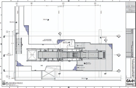
FIG 7.13 General arrangement plan, created in LayOut.
These drawings demonstrate the ability of LayOut to produce high-quality construction drawings.
Conclusion
The use of SketchUp and LayOut has improved our project flow because of the following reasons:
• They do not get in the way of our design work.
• They help us to better understand the physical fit and geometry of our projects.
• The process of modeling the existing facility, conceptual models, and final detailed construction models puts us closer to our work.
This is because of the intuitive interface and great flexibility of the program. SketchUp and LayOut tools are not menu driven or restricted to the modeling of specific elements. Their only limit is human knowledge and experience.