
Chapter 5

A Window Installation
James Steacy has a Bachelor of Architectural Science degree with a specialization in building science from Canada’s Ryerson University. Today, he works for a company based in the United States that focuses on helping homebuilders improve the quality and performance of their homes. There, he is implementing a new approach to creating construction procedures using SketchUp.
Lauren A. May has a Master of Arts degree in Professional Writing from Carnegie Mellon University in the United States and a Bachelor of Arts degree in English with a concentration in professional writing from Virginia Tech. She has spent years collaborating with homebuilding experts and technical illustrators to produce content that is clear and concise and can be leveraged.
Project: Documenting a Window Installation.
Tools: SketchUp Pro 7, LayOut 2.0, Adobe Photoshop CS4, and Adobe Acrobat 9 Standard.
A Window Installation is a project whose core focus is to create a document that takes someone step by step through the process of installing a window in a home. The document, known as a step-by-step document, uses a combination of words and images to successfully convey the proper techniques and processes to install the window from start to finish.
The audience of the step-by-step document is construction trades, the individuals on a construction site who build different parts of the home. Trades want practical, straightforward, and logical information that allows them to quickly grasp each step of the installation. They particularly favor using documentation that is heavily image-based and has minimal wording.
Two types of people collaborate to create a step-by-step document – a technical illustrator, James, and a technical writer, Lauren. James works on SketchUp and LayOut to create the illustrations and assemble the final output, and Lauren leads the planning, interviewing, and storyboard processes, assembles the text, and ensures the final output is consistent and correct.
The amount of time and effort it takes to complete a step-by-step document varies depending on the length and technical difficulty of the subject matter. Typically, one-third of the time is spent on modeling, one-third on writing, and one-third on document layout. The total amount of time we spent on this step-by-step document was approximately 24 hours, which included several stages of revisions. Our budget was just under US$2,000.
Project Context
The situation that surrounds a step-by-step document usually involves a homebuilder who is either proactively looking to instruct his/her trades on proper construction techniques or reactively seeking documentation on how to repair installation errors that were already made. Sometimes, a step-by-step document is part of a package of documents sent to the homebuilder; the package may have a scope of work, a checklist, and a specification sheet in addition to the step-by-step document.
Our four major constraints during the project were as follows:
1. The varying availability of knowledge: The subject matter expert brings a significant amount of knowledge to the step-by-step document but may not know the answer to everything. The ideal situation occurs when the expert’s knowledge encompasses a subject, and he or she is able to clearly explain the steps from start to finish. Usually, most of this information is gleaned during the storyboarding, interviewing, and review/revision stage. It is realistic to expect that the expert will need to consult personal research, engage in discussions with colleagues, and conduct multiple reviews of drafts, and so it is important to build buffer time into the development schedule, particularly during the review/revision stage. In our experience, it is during this stage that experts really excel because they have a concrete object – a print or digital copy of the document – to focus on and critique.
2. The limited resources: Time, money, and people are not always available to create a document that reaches the highest level of quality possible. For example, limited time to complete a model could lead to a quick decision between spending time to create a realistic building material texture using a scanner and Adobe Photoshop and taking the faster approach by simply selecting a color that is similar to the color of the building material.
3. The 2D output: Because the output is a print or electronic Adobe PDF document, at times, the 3D model will not translate well. More time and effort has to be spent on illustrating a 3D image when it will be in a 2D output.
4. The varying existence of the right plug-ins: The right plug-in can give the illustrator the ability to create whatever he or she envisions. Without the plug-in (and without the knowledge to create one), the illustrator has to develop techniques for getting around it. Usually, this translates into spending more time to manipulate the model to get the intended result. Making more plug-ins available will increase the potential to create even greater documents.
Technical Aspects
There are numerous reasons why SketchUp works well for creating the illustrations in the window installation step-by-step document, or for that matter, any homebuilding step-by-step document. SketchUp is a 3D modeling program, which allows the illustrator to create illustrations that mimic real life, rather than being 2D. SketchUp illustrations are cost effective to produce. The user interface and tools are relatively straightforward and simple. The ability to develop a library of materials and components significantly decreases the amount of time spent on modeling. Other illustration software like Adobe Illustrator and AutoCAD require each step to be an independent drawing. With SketchUp, a model can be used to illustrate all the steps, making changes easier and decreasing the number of times an item has to be illustrated.
Some additional positive attributes of SketchUp are as follows:
• The ability to use accurate and precise measurements so that objects can be drawn to real-life dimensions.
• The models can be at a 1:1 scale, mimicking real life.
• The 3D capability allows the illustrator to examine the building assembly from every angle.
• The ability to create materials that resemble real building materials helps clarify the illustration and bring real-life significance.
• The models can be drawn using as much or as little detail as needed, depending on the need to express a step properly.
To create the step-by-step document, the following SketchUp plug-ins were used: Profile Builder, Page Layers, Add Hidden Layer, Fredo Scale–Radial Bending, House Builder, and Hide All Unselected.
The specific SketchUp features that were used include the basic drawing tools (line, rectangle, circle, arc), copying (arrays), snaps, referencing, sections, groups, components, layers, and scenes.
Other than SketchUp Pro 7, three other types of software were used to create the document:
• LayOut 2.0: To lay out the document;
• Adobe Photoshop CS4: To create realistic textures;
• Adobe Acrobat 9 Standard: To reduce the file size of the document and transform it into a widely used format.
New Approaches
1. The concept: Creating step-by-step documents is not a common practice in the homebuilding industry. Typically, this type of documentation is not cost effective. Even more uncommon is the use of 3D modeling software to create the illustrations, so using SketchUp in this manner is a fresh way of looking at construction procedures in the industry.
2. The manner of using SketchUp: Using scenes and layers together to control the visibility of groups and components is a new way of using SketchUp to illustrate a construction procedure in a step-by-step manner.
3. The library: Creating a library (database) of materials and components decreases the amount of time spent on modeling. Many of the materials and components used in this step-by-step document were first developed for other step-by-step documents; since the items were saved in a library, they were easy to leverage.
4. The manner of using LayOut: Creating a scrapbook and a template speeds up the process of creating the final step-by-step document. A scrapbook is much like a library, except it is for LayOut, rather than for SketchUp. In addition, LayOut is usually used for conceptual design layouts for a client instead of for step-by-step documents.
Step 1: Planning
Goal: To create a roadmap that guides the development of the step-by-step document.
Inputs: Project plan, development schedule, and style guides.
The planning stage is arguably one of the most critical steps to the success of the final step-by-step document. It is during this stage that we first sat down to discuss the project’s background, set roles and responsibilities, create a development schedule, and identify resources. Typically, the background of a step-by-step document involves a homebuilder who is either proactively looking to provide his/her trades with clear instructions on how to properly install an aspect of a home or reactively looking to repair installation errors that were already made. We assigned our roles and responsibilities based on attributes like who is better equipped to interface with the client, to provide structure and scheduling, and to accomplish the end goal successfully. For this project, we built several small buffers into the development schedule to account for certain variable factors. These factors included the availability of the subject matter expert and the length of time for the review/revision stage; both frequently vary, in our experience, from document to document. We keep a text style guide and an illustration style guide as reference tools; it is valuable to make sure both are up to date at the start of a new project to ensure consistency.
Step 2: Storyboarding
Goal: To outline each step of the story told in the step-by-step document.
Inputs: Storyboard template and research materials.
Step-by-step documents lend themselves well to storyboarding. The story-board for this document included the following basic items: a main sketch, a secondary sketch, and a text box. Through storyboarding, we collaborated with the subject matter expert to determine the sequence of events (the steps) in the document, identify areas where more research was needed, and, most importantly, arrive at a stage where we could go away and begin to model and write.
Step 3: Classifying Objects
Goal: To make decisions about using illustrative and expressive objects and their role in the step-by-step document.
Inputs: Building material documents.
The nature of a step-by-step document is such that each step represents a snapshot of the installation. In the window installation step-by-step document, one step is to install OSB sheathing over the framing members. The next step is to install housewrap material on the exterior of the home. In both steps, the illustration only needs to show the item in one state – already installed. In other words, I needed only to model the object the way it would appear after being installed on the home. While this does not hold true in all cases, many times, trades do not need to see each individual board of the sheathing getting installed over the framing or each layer of housewrap being unrolled over the sheathing. Pairing the illustrations with the right text can give the trade an adequate amount of direction and context to complete the step. A conceptual object modeled in this manner can be classified as an illustrative object. Examples in the window installation step-by-step document include OSB sheathing, framing members, housewrap, and the stucco exterior finish.
Another classification of conceptual objects exists. This object displays an action that takes place, much like the unrolling of the housewrap material on the exterior of the home, or it displays an intermediate step that does not hold enough importance to receive its own step. This object can be classified as an expressive object, and it shows an action or something in action. They are usually used because the information being conveyed in the step is very complex. Examples in our window installation step-by-step document include arrows, construction tools, and housewrap as it is being cut to create an opening in the material for the window.
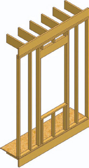
FIG 5.1 Illustrative object.

FIG 5.2 Expressive object.

FIG 5.3 The modeled objects – materials, tools, and window elements.
Step 4: Modeling Objects at a 1:1 Scale
Goal: To model objects according to reality.
Inputs: Building material documents.
Tools: SketchUp, House Builder, Profile Builder, and Fredo Scale–Radial Bending.
The illustrations in a step-by-step document meant for a construction trade should match reality as closely as possible. I model objects in SketchUp at a 1:1 scale. This is because the trade must physically re-create on the construction site what he or she sees in the illustrations.
Building materials tend to be easy shapes to model, and their dimensions are easy to acquire from the manufacturer. A good practice is to draw the shortest dimensions using the basic SketchUp drawing tools, Line L, Rectangle R, Circle C, and Arc A, and then use the Push/Pull tool P or Follow Me tool to extrude the length of the object. The Profile Builder plug-in can be useful for modeling many building materials, and the House Builder plug-in can be useful when modeling a lot of wood-framed walls.
Tip
FredoScale is an excellent plug-in with many useful tools. One tool in particular, Radial Bending, allows the illustrator to bend rectilinear objects along curves, an ability that can be used to create expressive objects, such as tape being applied to a surface.
Step 5: Creating Groups and Components
Goal: To make a modeled object a group or a component.
Tool: SketchUp.
Groups and components are the two types of objects created to organize a model in SketchUp. Groups are good for objects that are uncommon and need to be modified on a frequent basis, such as when you are showing the trade how to make various cuts in the housewrap. Components are good for repetitive objects that are identical in appearance, as well as objects that can be used over and over in numerous SketchUp models. Examples of components include construction tools, windows, and doors.
Once an object is modeled, determine whether or not it should be a group or a component. To make it a component, select all of the geometry of the object (triple-clicking on the object is one good way), and then click Make Component. Then, type in the name of the component, making sure to be very specific about what it is, and click OK.
To make an object a group, select all of the geometry of the object, right-click on the object, and then select Make Group. A faster way is to create a shortcut key, such as SHIFT+G. Every time you model an object, it is important to make it a group or a component. This keeps the geometry from interfering with other geometry in the model.
Step 6: Creating Materials and Making a Library
Goal: To create a realistic color or texture for a building material.
Inputs: Building materials.
Tools: Adobe Photoshop CS4, color scanner, and SketchUp.
A material in SketchUp is a color or texture. To make an illustration clear and easy to understand, it is best to use colors or textures that closely match the real-life object. Trades are then able to better associate what they see in the document with the actions they have to take on the construction site. It is important to note that standard construction drawings do not use colors or realistic textures; instead, they use arrows with text to point out each item in the drawing, increasing the amount of time it takes for trades to grasp the concept.
FIG 5.4 Object section.
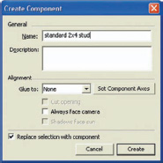
FIG 5.5 SketchUp’s Create Component dialog.
Typically, using colors that closely match the real-life object will give it enough believability. However, some objects need a little more than just color – they need texture. Textures help differentiate one object from another, especially when they are similar in color. A great way to create real-life textures is to use a scanner to scan the real building material and open the image in Adobe Photoshop. In Photoshop, modify the image so that it does not look like a repeating image or have a tiled appearance. Save the image as a JPEG, and then import it into SketchUp as a texture. In SketchUp, scale the texture and save it in a material library.

FIG 5.6 Creating an object.

FIG 5.7 Object with textures applied.
Tip
If two or more instances of the same building material are layered over each other in a model, create a copy of the SketchUp color or texture and then lighten or darken it. This can help show that there are multiple layers of the same building material.
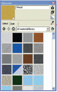
FIG 5.8 SketchUp’s Texture library.
Step 7: Layering
Goal: To organize objects on layers.
Tool: SketchUp.
All groups and components need to be assigned a specific layer, which later allows you to create scenes. To avoid layering issues, all lines and faces should be on Layer0. Open the Layers palette by going to Window > Layers, and then also open the Entity Info palette by going to Window > Entity Info. Both should be open on screen. In the Layers palette, click on the plus symbol to add a layer. Give the new layer a name that is very specific to the object(s) that will be placed on it, such as naming it “window” for a window component. Select the object by clicking the Selection button or by hitting the spacebar on the keyboard. Then, in the Entity Info palette, select the appropriate layer from the drop-down menu. Repeat this process until each of the objects in the model exists on their own layer.

FIG 5.9 Objects associated with different layers.
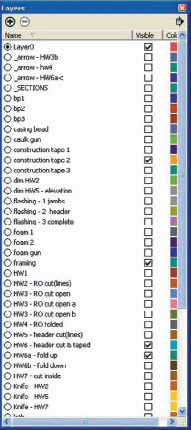
FIG 5.10 The layers palette.
Step 8: Creating Scenes
Goal: To create the steps of the document using scenes.
Tools: SketchUp, Page Layers, and Add Hidden Layer.
There are two important reasons to create scenes. One is to set the viewpoint, and the other is to capture which layers are visible. The first scene represents the first step in the step-by-step document, and the final scene represents the last step in the document.
Tip
Try to make all the necessary layers before creating scenes. This is important because there is a default setting in SketchUp where any new layers automatically appear on all current scenes. You then have to uncheck the new layers and update the scenes. Plug-ins like Page Layers and Add Hidden Layer can help with this problem.
Label scenes using a naming convention that works for you. It is best to use short names that allow for more scene tabs to fit across the top of the screen.
Before creating a scene, select the type of viewpoint and aspect that work best for the document. Typically, 3D construction drawings are isometric, parallel projections. Most of the drawings in our window installation step-by-step document are isometric, parallel projections; at times, other viewpoints and aspects were used in order to successfully convey information to the trade.

FIG 5.11 Scene tabs.

FIG 5.12 Assembling the documentation in LayOut.
After setting up the viewpoint and aspect, select the checkboxes for the layers that need to be on for the step. A good idea is to set the viewpoint to Zoom Extents. Next, it is time to create the first scene. Go to View > Animation > Add Scene. To make the following scene, repeat the process.
Step 9: Setting Up the SketchUp Model in LayOut
Goals: To set up the SketchUp model in LayOut and apply the Hybrid rendering mode.
Tool: LayOut 2.0.
First create a template for the document in LayOut. I use templates to decrease the amount of time it takes to set up, manage, and make changes to the document. The template for the window installation step-by-step document had a title block, which includes a title, subtitle, and page number, and a series of LayOut layers to help organize content in the document. The document’s various layers were Guidelines, Arrows, Text, Title Block Text, Page Numbers, Secondary Graphics, Primary Graphics, and Background.
To choose a template, click on File > New From Template and then select the template. Next, to insert the SketchUp model into LayOut, click on File > Insert and then browse for the file. This places the model in the LayOut document.
LayOut has three different ways to render a SketchUp model: raster (default), vector, and hybrid. Raster images are pixel based and can look bad when zoomed in too much. Vector images are coordinate based, not pixel based, and so the lines and colors always look crisp. The downside to vector images is the fact that material textures are not displayed. Hybrid images have the best characteristics of both because the lines are vector based and the colors and textures are raster based.
Tip
Customize the user interface to add and remove buttons and arrange the side tray according to the palettes used the most.
In LayOut, select the SketchUp model. Then, in the SketchUp Model palette at the bottom, click on the drop-down menu in the bottom right-hand corner and select Hybrid. At this point, it is good to place the model where it will exist in the document. If necessary, set the style and scale of the SketchUp model in the SketchUp Model palette.

FIG 5.13 LayOut’s three rendering modes: Raster, Vector and Hybrid.
Step 10: Creating the Document in LayOut
Goal: To assemble the final step-by-step document.
Input: SketchUp model.
Tool: LayOut 2.0.
To begin to set up the first page, set the model to the appropriate scene. Right-click on the model, select Scenes, and choose the scene from the list. A yellow warning sign will appear near the bottom right of the model; this means the model within the page is updating. Note that LayOut 2.0 still has a few issues, so wait until the model finishes updating before moving on to the next step. Once the model finishes updating, add the secondary illustrations, arrows, blowups (zoomed portions of the model), and text. The point of the document is to clearly illustrate a construction process so that secondary graphics, arrows, blowups, and text really help support a step.
Tip
Scrapbooks are a useful tool in LayOut for saving and reusing elements that repeat throughout the document. Common items to save in a scrapbook include arrows, text boxes that are of a specific size and font, and other illustrative objects. A scrapbook functions much like a component library in that it acts as a place to store common items.
After creating the first page, copy it by going to the Pages palette and clicking the Duplicate Selected Page button. This makes a copy of the first page and places it as the second page. Then, update the model on this new page to be the appropriate scene. The reason for making a new page by copying the page before it is that the model on the new page will be in the same location as it was in the previous page. This eliminates repeatedly having to reinsert the SketchUp model and its secondary illustrations, arrows, blowups, and text. Repeat this process until the step-by-step document is complete, and then have the subject matter expert review it for technical accuracy.
On a side note, when exporting the document to an Adobe Acrobat PDF format, the hybrid rendering of the model results in a large file size. Reduce the file size by going to Documents > Reduce File Size in Acrobat. Our 28-page window installation step-by-step document was reduced from 25.5 to 2.92 MB.
Step 11: Leveraging the Content
Goal: To repurpose the SketchUp components, models, and materials; the text; and the document.
Tools: SketchUp, Umbraco, and Canto Cumulus 7.
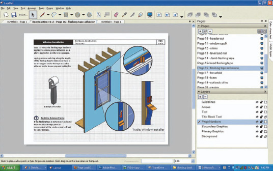
FIG 5.14 Example of a page in LayOut using one scene.

FIG 5.15 Example of a page in LayOut using three scenes.
Leveraging content means to repurpose it. It is great to create a single-window installation step-by-step document, but it is even greater to repurpose the SketchUp components, models, and materials; the text; and the document itself in different formats, for different clients, and so on. It is a simple concept – the more often content can be repurposed, the more value it provides.
Our SketchUp components, models, and materials from the step-by-step document exist in an organized series of folders as a library (database). We could upload the text to a content management system (CMS) and serve it to a website as, for example, a text-based series of steps or have it automatically reassembled into an article. We like Umbraco, an open-source CMS from Denmark based on Microsoft’s ASP.NET. Or, we could upload the illustrations to a data asset management system (DAMS) to help manage them and allow others to readily search and locate them for future uses. We use Cumulus 7, a DAMS solution from Canto that helps arrange, share, and track different types of content. We have thousands of illustrations and photographs stored in Cumulus. These examples are just the start of a long list of tools to assist in leveraging the content. That is the end goal when creating quality content – for it to live a long life in many forms.
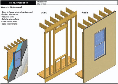
FIG 5.16 A final completed page.
Conclusion
SketchUp Pro 7 enables illustrators to create clear, in-depth, step-by-step procedures faster and easier than other common software packages, including Adobe Illustrator and AutoCAD. Considering SketchUp is a fraction of the cost; it is a very cost-effective tool to use. As for the future, there is untapped potential to take the models and documents to the next level. Models can become 2D drawings for standard construction drawings, slide-shows, animations, and interactive web models, to name a few. Combine SketchUp and the various potential outputs with the smart, innovative people developing Ruby scripts and Google’s program becomes a very powerful tool.
Resources
Software
SketchUp Pro 7 (includes LayOut 2.0) – US$495, excluding taxes.
Adobe Acrobat 9 Standard – US$299, excluding taxes.
Photoshop CS4 – US$699, excluding taxes.
Umbraco – US$1,146, excluding taxes.
Canto Cumulus 7 – ≈ US$12,000, excluding taxes.
SketchUp Plug-ins
Profile Builder, by Dale Martens. Available at http://www.smustard.com/script/ProfileBuilder.
Page Layers, by Rick Wilson. Available at http://www.smustard.com/script/PageLayers.
Add Hidden Layer, by Jim Foltz. Available at http://sketchuptips.blogspot.com/2007/08/add-hidden-layer.html.
Fredo Scale–Radial Bending, by Fredo6. Available at http://forums.sketchucation.com/viewtopic.php?t=17948.
House Builder, by S. Hurlbut. Available at http://www.crai.archi.fr/RubyLibraryDepot/Ruby/em_arc_page.htm.
Hide All Unselected, by Todd Burch. Available at http://www.smustard.com/script/HideAll.