
Chapter 1

Creating Virtual Concept Models in SketchUp
Jean Thiriet is an architect, qualified in 2008 by the école nationale supérieure d’architecture de Nancy (also called EAN). A passionate user of 3D, he has been working for a practice that creates real-time virtual models since finishing his studies. His other interest is teaching, and in 2009, he created the website wip-archi.com, which is dedicated to conveying the concepts of modeling and rendering, so indispensable in today’s profession, to both students and professionals alike.
Project: Virtual models in SketchUp.
Tools: SketchUp 6, Artlantis, Vray, Photoshop, and Internet.
Jean Thiriet: “The last few years have seen an unprecedented boom in the use of 3D tools. More and more professionals are beginning to notice the undeniable advantages of these virtual approaches, and the growing presence of SketchUp in architecture practices is the best proof of this. In spite of its novel approach, SketchUp often still finds its place in the production pipeline at the same stage as traditional model makers: at the end of the design process. However, given the potential that it possesses, it would be interesting to try to push for new working methodologies based on a simple concept: the virtual model.”
“This model grew and was added to as the project evolved, and it was possible to use it throughout the process to create more traditional graphics (rendered images, for example), whose common origin guaranteed an overall visual coherence.”
Project Context
Although many people consider it to be a “basic” program, SketchUp can be integrated into a rich and complex creative process, while at the same time remaining quick and easy to use.
Technical Aspects
Since this project was based on existing building, the design process started with a site survey and desk study, followed by importation of all the data into AutoCAD. This laid the groundwork for future design work.
We soon realized that we would need a virtual model. Using this model, we were able to easily visualize the impact of the many design choices throughout the conceptual stage, something that is indispensable when working with renovations. The 3D construction of the surrounding site backed up this approach and made it easy to take decisions that affected the overall, wider urban vision.
The model for the conceptual phase was often constructed using a fairly empirical method, the volumes being drawn in space with neither a priori research nor the use of clearly defined structural elements (walls, windows, slabs, etc.).
As the project progressed, these purely geometric objects – which were, at this stage, fairly malleable – were transformed into groups and components that were then organized into a hierarchy of layers, the implementation of which makes sense of the whole project, making it more usable and concrete.
This free-form approach explains the success of SketchUp in the conceptual research phases, since it offers a flexibility that other architectural software that is based on parametric objects simply cannot match.
Tip
SketchUp cannot deal with groups of layers: This can make it difficult to keep a clear overview of the project, especially when the number of layers begins to grow large. Creating numbered categories allows you to get around the problem and gives you a reasonable and efficient organization (for example, 01 for the gross structure, with layers 01_Columns, 01_Slabs, 01_Walls, etc.).
Once the project design had stabilized, the next step was the presentation stage. First of all, the model showed a relative uniformity of scale and definition of space (here, at about 1:200), and details were then added to certain specific areas. This method reduced the construction time for the whole project and left more flexibility for further adjustments.
In order to create high-quality images, it is often necessary to go beyond SketchUp’s rendering capabilities, notably in terms of complex reflection effects, material rendering, or lighting calculations. There are many programs capable of utilizing the data from the 3D model, and for this project, we used two programs in particular: Artlantis Studio and Vray for SketchUp.
Artlantis is a stand-alone application that takes in the data exported from another 3D modeling program. This program offers a real-time preview of applied material effects, coupled with a very approachable interface; it makes it very easy to adjust the overall look of a scene (lights, textures, etc.).
Vray is a rendering engine, developed originally for 3D studio Max, then ported to several other programs, with SketchUp being one among them. Unlike Artlantis, it is integrated directly within Google’s program, where it posts its own toolbar. The renderer offers many advanced control possibilities, something that can put off new users at first. Luckily, sets of parameters can be saved as preset files that can be easily reused, and only a few clicks are necessary to generate a basic render.
Tip
Many websites offer these parameter files for use directly within Vray, and so it is not necessary to know all the ins and outs of the program to make use of it. The parameter files utilized here are from the website www.wip-archi.com.
The use of different pieces of software allows you to really appreciate the flexibility of SketchUp and underlines the necessity of a reasoned approach at every step of the way.
New Approaches
Treating the modeling phase as something intimately tied up with project development, and seeing the images produced as a spur to further development, rather than as an end in themselves, is quite far removed from the classic approach. However, it is bound up with the very nature of SketchUp.
Having a discussion about the model, asking yourselves the questions raised by it, and then creating renders to answer those questions are much more interesting than arbitrarily choosing some points of view in your model, simply rendering them out in 3D, and showing them to the client.
Finally, this “decompartmentalized” use of software in a dynamic, collaborative pipeline (SketchUp, Vray, Artlantis, Photoshop, Internet, etc.) and the exchange of data in various formats represent an original and efficient approach.
To illustrate this, we are going to look at three distinct cases: three images generated from the project. They were not intended to convey the same information and would, therefore, be produced using different methods. Nevertheless, they were all created from the same 3D model that formed the basis of the project.

An Aerial View
Presenting the building in its entirety, showing its relationship with the urban fabric, entailed the creation of an overall view that summed up the intentions and the impact of the project.
Stage 1: Define a Composition
Objectives: Make choices that optimize how the image will be read.
Data: 3D model.
Tools: SketchUp and Vray.
Here, we tried to get over a notion of the hierarchy of the elements shown, in order to stress the major points of the project in relation to its environment.
To do this, the urban context was modeled entirely of schematic blocks rendered in “clay render” mode. The easiest way of achieving this is to choose an appropriate preset within Vray: In Vray’s options, click on File > Load, choose a preset (the file extension is .visopt) and start the render.
Thanks to this approach, it was easy to see the scale and relation of the principal elements, without overburdening the image with graphic information.
The building, framed at the center of the scene, was going to be rendered in color, primarily to stress the importance of the landscaping aspects of the project. The numerous clusters of trees were largely responsible for the character of the spaces, and a graphic representation of this was needed.

Stage 2: Updating the Model
Objectives: Adding elements to communicate the intentions of the project.
Data: SketchUp components.
Tools: SketchUp and Component Spray plug-in.
At this scale and viewing angle, it was apparent that placing photorealistic 2D trees would not make reading the project any easier and would entail long hours of manipulation in Photoshop.
We, therefore, went for schematic 3D trees that had sufficient explicit volume to render the image readable. However, in light of the number of elements that we needed to place, this was going to be a complex operation: SketchUp does not have any tools that could help in this regard.
Luckily, a Ruby script programmer has come up with a solution to get around this constraint. Ruby plug-ins, often free and developed independently by a dynamic community of enthusiasts, provide quick-and-easy solutions in cases too numerous to mention and fill many of the holes in the original program. We used the Component Spray plug-in, which allows you to easily duplicate components across a surface using a simple click (or across a chosen geometric shape: square, circle, etc.). The script also includes a function that randomly changes component scale and rotation, which gives a very natural-looking appearance to the results of multiple copy operations. The same method was used to place the people in the scene.
Thanks to the Component Spray Ruby, you can use various types of duplication to place complex vegetation consisting of different types of components, all placed in one single operation.

FIG 1.3 Updated model, rendered with Vray.
Stage 3: Refining the Render Further
Objectives: Compositing the different elements to obtain the final image.
Data: Renders from SketchUp and Vray.
Tools: SketchUp, Vray, and Photoshop CS.
Once we have the two images (both the “clay render” and color images produced with Vray), it was simply a matter of compositing them in Photoshop and applying a mask to allow the one layer to show through the other where necessary.
Tip
A Layer Mask can be added to any layer within Photoshop – apart from Background layers, of course (from the Menu Bar, Choose Layer > Layer Mask > Reveal All). Adjusting the visibility of the layer is simple: with the Layer Mask selected in the Layers palette, painting on your layer with a black brush will make the pixels of that layer disappear; painting in white will bring them back again.
In order to increase the readability of the whole image, and in particular the white of the massing model, we composited the edges from the SketchUp render on to the render created in Vray. If your software allows you to create a renderer with exactly the same camera position and angle as in your SketchUp scene, it is easy to composite the two. To do this, you simply need to take a screenshot in SketchUp’s Hidden Line mode (with the background set to white) and place it in a new layer in Photoshop, overlaying the previous render. You then simply need to change the layer’s Blending Mode (usually to Multiply). This will knock out the white of the black-and-white layer, revealing the full-color image underneath, but will keep the black edges intact.
Using this method, you can create some fairly original-looking renders, halfway between photorealism and a hand-drawn effect.
Finally, since the green spaces are particularly important as regards the use of the space as a whole, they were brought more to the fore by giving them a specific texture using Photoshop’s Clone Stamp tool.
Tip
A realistic-looking grassy surface can be easily obtained by using any sort of grass image, painted at low opacity on any areas rendered with a lawn texture. The variations in shades of green create a realistic appearance, eliminating the tiling effects often observed in these types of textures.
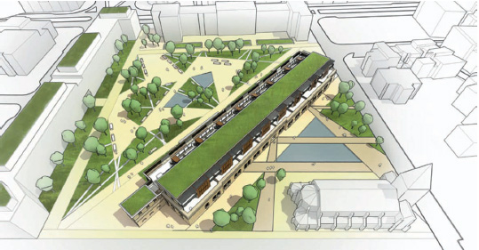
FIG 1.4 Final image.
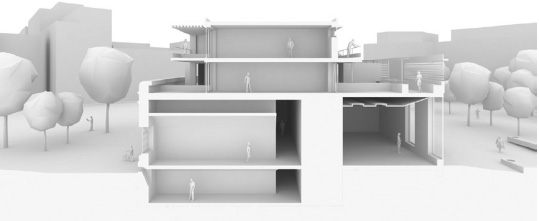
Principal Section
Since the project was based on an existing building and the brief called for a multifunction use, the final scheme consisted of many complex, interlocking spaces and varying usage zones. It was, therefore, necessary to communicate these clearly in order to convey the overall idea of the project. With this in mind, a section seemed ideal in this regard.
Stage 1: Choose an Approach and Understand the Constraints
Objectives: Decide on the type of render and the method that will allow you to achieve it.
Data: 3D model.
Tools: SketchUp.
From the start, we chose a “clay render” style, in order to place the accent on the building volumes themselves and not on the extraneous details that might hinder the reading of the whole scheme. The section view for this stage is further accentuated by rendering it in perspective, something that is richer and more dynamic than a simple 2D cut.

FIG 1.5 Simple white render of the section cut.
SketchUp makes it easy to dynamically place section cuts, thanks to its dynamic Section Plane tool. However, these cuts are “virtual,” and the model always remains intact.
Unfortunately, rendering engines work on the entire geometry of the model so that the section cuts would not appear in any renders produced by third-party programs. This means we needed to turn to other methods to achieve the desired result.
If you are using Artlantis, it is possible to get the same effect by using its own Section Cut tool. Unfortunately, to get a monochrome model, it would be necessary to replace all the materials one by one with a uniform white texture, something that entails a considerable time investment. For these reasons, we chose at this stage to work with Vray, to obtain a very high-quality “clay render,” but this approach would require some modification to the model.
Stage 2: Adapting the Model
Objectives: Creating a model with a section cut that can be rendered by third-party programs.
Data: 3D model.
Tools: SketchUp, Zorro 2, and Section-Cut Face plug-ins.
Now, the rendering engine had been chosen; next, we needed to solve the problem of how to create a model with a section cut. We could modify all the groups in the model one by one, cutting them where we want our section plane to be, using the Intersect Selected tool, but that would be an extremely long and tedious operation.
Luckily, in this situation – as in so many others – we can get around the initial limits of the program, thanks to the ingenuity of Ruby script programmers. To resolve the current problem, we just need to use the Zorro 2 script, which automatically erases all the geometry on one side of a SketchUp section plane, allowing the model to then be exported to a rendering program with a section cut visible.
Tip
Since the operation carried out by the Zorro 2 script is destructive (it erases geometry) and is sometimes subject to errors, it should always be run on a copy of your model.
SketchUp, being a surface modeler, produces open section cuts when used with the Zorro 2 plug-in. This would be a good point to run the Section-Cut Face plug-in, which, as its name suggests, caps the open ends of the section cut with a face, giving a solid edge to the section – a much more aesthetically pleasing result.
Stage 3: Fine-Tuning the Render
Objectives: Bringing together several elements to obtain the final image.
Data: Rendered images from Vray and SketchUp.
Tools: SketchUp and Photoshop.
Once the image is generated, there are only a few adjustments that need to be carried out in Photoshop to obtain a convincing result.
Often, you only need to adjust an image’s levels (from the Menu Bar, choose Image > Adjustment > Levels) to tweak the contrast, to bring out details, and to make the image more clearly readable. The Levels palette shows a histogram and three sliding cursors: Black, Gray, and White. By sliding these cursors, you can adjust the luminosity values for different parts of the grayscale spectrum far more accurately than you could with the Luminosity tool.
Tip
To obtain a quality “clay render,” it is often a good idea to create two different renders with two types of illumination: One uses the sun and creates high-quality projected shadows and the other uses only ceiling lights to produce a more uniform level of detail. Compositing the two in Photoshop produces a result that is precise and has great contrast.

FIG 1.7 Final image.
An Interior Perspective
Once the functioning and the logic of the building had been clearly explained, it was necessary to present the interior ambience of the project in more detail. To this end, we chose to create the perspective of the exhibition space, a pivotal point between the extension and the existing structure.
Stage 1: Dressing the Envelope
Objectives: Increase the level of detail in the model in the area under consideration.
Data: 3D model and images (textures).
Tools: SketchUp and Internet browser.
First of all, we carried out a texture search for the stone wall, the wooden floor, and the concrete for the walls. A few clicks on sites containing free texture libraries (such as CGtextures.com) will turn up a vast array of suitable textures.
Once the image was downloaded, it needed to be integrated into the model’s geometry. To do this, we first of all needed to apply a material to an object (using the Paint Bucket tool), and then, using the Materials Editor (the Colors palette on the Mac), we needed to assign the texture to our material. To do this on the Windows version, go to the Edit tab, click the Use Texture Image checkbox, and navigate to your texture in the dialog box that appears. To do this on the Mac, go to the Colors palette, choose Materials in Model (the little brick icon), right-or Ctrl-click on your material’s swatch, and choose Edit… from the contextual menu. Now, from the Edit pane, you can change your material’s bitmap texture, overall dimensions, and hue to obtain a more precise effect.

FIG 1.8 Textured model.
Stage 2: Dressing the Space
Objectives: Fitting out the model to convey the nature of the space.
Data: 3D model, images, and SketchUp components.
Tools: SketchUp and Internet browser.
Once the boundaries of the space have been defined, it needs to be fitted out. Since the building was a former military barracks in a garrison town, we immediately thought of using Vauban as a theme.
Using the name as a keyword for an Internet image search, we easily turned up many of Vauban’s original plans, which we simply had to drag and drop into SketchUp to create exhibition displays.
At the same time, research on Wikipedia returned a bibliography whose first paragraph, copied into SketchUp’s 3D Text tool, became an integral element of one of the wall displays. Also, by using the 3D Text tool to change the font and the size of the text, we were able to create a convincing title for the exhibition.
Finally, still adhering to the same theme, Google’s 3D Warehouse offers no end of models of Star (Escarpment) Fortresses (a specialty of Vauban): You just need to reduce them down to the appropriate scale to compete the exhibition.

FIG 1.9 Improved model.
Stage 3: Creating an Image
Objectives: Rendering a photorealistic image of the space (lighting, materials).
Data: 3D model.
Tools: Artlantis.
After fitting out the exhibition space, we then moved on to the rendering proper. In view of the number of different materials to adjust and the number of light sources that needed to be placed, we decided on Artlantis, since, in such a situation, Artlantis is far more flexible and easy to use than Vray.
Rendering the model began by opening the SketchUp file directly in Artlantis; there is no need to export from SketchUp in an intermediate format beforehand. Artlantis automatically converts SketchUp’s scenes into cameras, and you just need to click on one of these to select the desired view and obtain a previsualization render of the space.
Tip
Take care to note the visibility of your layers in SketchUp when you save the .skp file before loading it into Artlantis: Any hidden elements will not show up in Artlantis.
After placing a bump map on the wall texture, adjusting the reflection of the flooring, and defining the intensity of the neon luminaires in the ceiling, we only needed to hit the render button to produce an image at the chosen resolution.

FIG 1.10 Model rendered in Artlantis.
Stage 4: Finishing Touches
Objectives: Work on the render to produce the final image.
Data: Images from Artlantis and SketchUp.
Tools: SketchUp and Photoshop.
To be efficient at this stage, you need to appreciate the contribution that each program makes to the final render and to use that program only within its field of application.
After several minutes of setting up and a very short render time, the “raw” render produced by Artlantis was somewhat lifeless, but contained enough definition in the material and lighting effects to enable us to produce our final image.
It would have been possible to rework the lighting intensity or the color of the Sun directly within Artlantis and then to render again to produce an image more in line with what we wanted. However, this process can take time, since you are not always certain of the results that you will obtain from any given render. Luckily, we were able to use Photoshop to achieve the desired results within a relatively short space of time, all the while conserving flexibility, mainly by using the Levels, Curves, and Color Balance commands.
Similarly, the silhouettes of people that give life and a sense of scale to the scene can also be added in Photoshop, using classic 2D cutouts. However, it is sometimes difficult to judge the scale of each individual silhouette within a perspective, and so, in order to save time, these cutouts can be placed in the SketchUp file itself, simply by dragging and dropping them from the Component library, but placing them on their own layer. This allows the figures to be exported independently and later composited in Photoshop. This was the route that we chose, since we wanted an “abstract” silhouette effect, without shadows or reflections.
Tip
You need to analyze all the constituent elements of the model in the same way as the 2D silhouettes. For instance, you can place vegetation into the model as 3D objects. With trees and shrubs especially, this will allow you to obtain very precise shadows. Unfortunately, the geometric complexity entailed by such models brings with it a considerable hike in render time and file size in SketchUp. Therefore, it is often preferable to quickly composite masked photos of trees directly within your image-editing software.

Conclusion
In this project, it can clearly be seen that constructing a model in SketchUp serves both the conception and presentation phases of a project equally well, providing both flexibility and efficiency.
The flexibility and versatility of the platform allow for the exploration of multiple aspects of the project and give you the ability to precisely convey complex architectural intentions to the client.
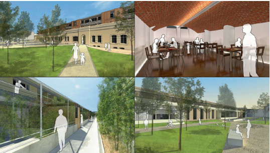
FIG 1.12 Some examples of rendering compositions.
Finally, using a model means that you can view your project from any angle, but at the same time, it teaches you the importance of correctly framing and composing a render. The growing presence of 3D tools in today’s projects often leads to a proliferation of ill-thought-out images, and the readability of the entire project suffers as a result of this. This is why final compositing work in an image editor is always necessary, meaning that a few well-chosen and well-presented images should be sufficient to efficiently convey the essence of a building.
Resources
Software
SketchUp 6.4.
Artlantis Studio 2.0.
Vray for SketchUp.
Photoshop CS3.
SketchUp Plug-ins
Component Spray by D. Bur.
Zorro 2 by D. Martens.
Section-Cut Face by TIG.
These can be found on the Ruby forum at www.sketchucation.com and in the database of the CRAI laboratory at http://www.crai.archi.fr/RubyLibraryDepot/.
Vray preset files, Artlantis workflow
Miscellaneous