
In an ideal world, all areas of your network would be connected with high-capacity links, and every server would communicate with each other without latency or congestion. Computers would unite and throw off the bandwidth shackles that tie them down. Alas, no real networks work this way, and traffic concerns must be taken into consideration in all but the smallest, single-server Active Directory (AD) structure. Windows Server 2003 expands upon Active Directory’s replication capabilities introduced in Windows 2000 with a range of new features and functionality. Consequently, the introduction of these new capabilities greatly increases the capabilities of Active Directory and also changes some of the fundamental design elements of AD replication.
Windows Server 2003 improvements in Active Directory replication are directly drawn from lessons learned in Windows 2000. Replication compression can now be disabled in well-connected sites, enabling designers to sacrifice bandwidth for processor utilization in domain controllers (DCs). In addition, novel concepts such as DC Promotion from Media allow global catalog servers to be created from CDs or other media, which greatly increases DC placement flexibility. Improvements such as universal group caching on domain controllers allow remote domain controllers to function as global catalog servers by caching frequently used universal group membership locally. New functionality, such as support for IPv6, has also been added to further improve the operating system.
The redesign of the replication structure in Windows Server 2003 fixes design limitations that have thwarted replication plans in the past. Problems with replication design can potentially cripple a network, and it is therefore wise to put some serious thought into the proper layout and design of an effective replication scheme.
This chapter focuses on the definition of the components of Windows Server 2003’s Active Directory that make up its replication topology. It details design strategies for Active Directory sites and provides real-world examples to illustrate the principles behind them. In addition, new components related to AD infrastructure such as support for IPv6 (Internet Protocol version 6) are outlined and described.
All enterprise directory environments must include mechanisms to synchronize and update directory information across the entire directory structure. In Windows Server 2003’s Active Directory, this means that every domain controller must be updated with the most recent information so that users can log in, access resources, and interact with the directory accurately.
Active Directory differs from many directory services implementations in that the replication of directory information is accomplished independently from the actual logical directory design. The concept of Active Directory sites is completely independent from the logical structure of Active Directory forests, trees, and domains. In fact, a single site in Active Directory can actually host domain controllers from different domains or different trees within the same forest. This allows for the creation of a replication topology based on a WAN structure, while the directory topology can mirror the organization’s structure.
Active Directory was specifically written to allow for the creation, modification, and deletion of directory information from multiple domain controllers. This concept, known as multimaster replication, allows no one domain controller to be authoritative. If any domain controllers go out of service, any one of the rest of the domain controllers can make changes to directory information. Those changes are then replicated across the domain infrastructure. Of course, there needs to be some level of control on this type of replication so that only the most recent changes take precedence. This type of control is realized in Active Directory through the concept of Update Sequence Numbers (USNs).
All enterprise directory services implementations require a mechanism to handle the incremental storage of changes made to directory objects. In other words, whenever a password is changed, that information must be accurately passed to all domain controllers in the domain. This mechanism must also be able to apply only those changes that occurred at the most recent intervals.
Many directory services implementations relied on exact time synchronization on all domain controllers to synchronize information. However, keeping the clocks of multiple servers in sync has been proven to be extremely difficult, and even slight variations in time could affect replication results.
Thus was born the concept of the Update Sequence Number. Active Directory utilizes USNs to provide for accurate application of directory changes. A USN is a 64-bit number that is maintained by each domain controller in Active Directory. The USN is sequentially advanced upon each change that is made to the directory on that specific server. Each additional domain controller also contains a copy of the last-known USN from its peers. Updates are subsequently made to be more straightforward. For example, when requesting a replication update from Server2, Server1 will reference its internal table for the most recent USN that it received from Server2 and request only those changes that were made since that specific number. The simplicity of this design also ensures accuracy of replication across the domain environment.
The integrity of replication is assured with USNs because the USN number is updated only upon confirmation that the change has been written to the specific domain controller. This way, if a server failure interrupts the replication cycle, the server in question will still seek an update based on its USN number, ensuring the integrity of the transaction.
The concept of USNs does not completely eliminate the role of proper time synchronization in Active Directory. It is still important to maintain accurate time across a domain environment because of the possibility of replication collisions. A replication collision is an inaccuracy in replicated information that takes place because of changes that are enacted on the same object, but before that change has been replicated to all domain controllers. For example, if an administrator resets a user’s password on Server1, and another administrator resets the same user’s password on Server2 before Server1 has had a chance to replicate that change, a replication collision will occur. Replication collisions are resolved through the use of property version numbers.
Property version numbers are applied as an attribute to all objects within Active Directory. These numbers are sequentially updated and time-stamped whenever a change is made to that object. If a replication collision occurs, the property version number with the latest time stamp will be enacted, and the older change will be discarded. In the example from the preceding section, the password change with the latest time stamp will be applied to the user.
This concept subsequently requires accurate time synchronization to be a priority for an Active Directory domain—although it is not as critical as in other directory services implementations that rely on it for all replication activity.
Connection objects are automatically generated by the Active Directory Knowledge Consistency Checker (KCC) to act as pathways for replication communication. They can be manually established, as well, and essentially provide a replication path between one domain controller and another. If, for example, an organization wants to have all replication pushed to a primary domain controller (PDC) before it is disseminated elsewhere, direct connection objects can be established between the two domain controllers.
Creating a connection object is a straightforward process. After one is created, Windows Server 2003 will not attempt to automatically generate a new one across the same route unless that connection object is deleted. To manually set a connection object to replicate between domain controllers, perform the following steps:
Open Active Directory Sites and Services.
Expand Sites<Sitename>Servers<Servername>NTDS Settings, where Servername is the source server for the connection object.
Right-click NTDS Settings and choose New Active Directory Connection.
Select the target domain controller and click OK.
Name the connection object and click OK.
Right-click the newly created connection object and select Properties to open a properties page similar to Figure 7.1. You can then modify the connection object to fit any specific schedule, transport, and so on.

Note
The connection objects that appear as automatically generated were created by the KCC component of Active Directory to provide for the most efficient replication pathways. You must therefore have a good reason to manually create these pathways because the automatically generated ones usually do the trick.
Administrators who are not accustomed to Active Directory’s replication topology may become confused when they make a change in AD and find that the change is not replicated immediately across their environment. For example, an administrator may reset a password on a user’s account, only to have that user complain that the new password does not immediately work. The reason for these types of discrepancies simply lies in the fact that not all AD changes are replicated immediately. This concept is known as replication latency. Because the overhead required in replicating change information to all domain controllers immediately is large, the default schedule for replication is not as often as may be desired. Replication of critical information can be forced through the following procedure:
Open Active Directory Sites and Services.
Drill down to Sites<Sitename>Servers<Servername> NTDS Settings, where Servername is the server that you are connected to and that the desired change should be replicated from.
Right-click each connection object and choose Replicate Now, as shown in Figure 7.2.

Another useful tool that can be used to force replication is the repadmin command-line tool. This tool is installed as part of the Windows Server 2003 Support Tools on the server media. Once installed, repadmin can be used to force replication for the entire directory, specific portions of the directory, or to sync domain controllers across site boundaries. If the bandwidth is available, a batch file can be effectively written to force replication between domain controllers, effectively making the directory quiescent. Figure 7.3 illustrates an example of a simple batch file that forces the replication of all Active Directory naming contexts between two domain controllers.

In addition to the repadmin utility, the Support Tools install the replmon utility, which allows for a graphic display of replication attempts and history for domain controllers. This utility can be useful for giving advance notice of replication problems before they become major issues. Figure 7.4 illustrates how this utility can display replication information between domain controllers in Active Directory.

The default replication schedule can be modified to fit the needs of your organization. For example, you might have very high bandwidth between all your domain controllers in a site and decide to change the default schedule to as low as fifteen minutes. To make this change, perform the following steps:
Open Active Directory Sites and Services.
Drill down to Sites<Sitename>.
Right-click NTDS Site Settings and choose Properties.
Click Change Schedule.
Set the Schedule to Four Times Per Hour, as shown in Figure 7.5.
Click OK to save any schedule changes and then OK again to close the NTDS Site Settings Properties page.

Of course, changing this schedule comes with some caveats, namely watching for increased network bandwidth consumption. You should match the trade-off of your organization’s needs with the increased resource consumption levels required.
Active Directory in Windows Server 2003 allows for the dissemination of replication traffic in the form of either IP (RPC) or SMTP packets. This functionality allows for the flexibility to choose SMTP traffic if no direct link exists between two disparate sites in AD.
IP replication traffic is utilized in most cases for intersite communications. This type of traffic uses the familiar Remote Procedure Call (RPC) communications to send information between different sites, making it an ideal form of communications for most WAN-based networks.
The basic unit of Active Directory replication is known as the site. Not to be confused with physical sites or Exchange 5.5 sites, the AD site is simply a group of highly connected domain controllers. Each site is established to more effectively replicate directory information across the network. In a nutshell, domain controllers within a single site will, by default, replicate more often that those that exist in other sites. The concept of the site constitutes the centerpiece of replication design in Active Directory.
Specific functionality that affects sites has evolved since the days of Windows 2000. Windows Server 2003 introduces numerous replication enhancements that directly affect the functionality of sites and allow for greater design flexibility in regard to site design:
GC universal group membership caching
Media-based domain controller creation
Linked-value replication
ISTG algorithm improvements
No global catalog full synchronization with schema changes
Ability to disable replication packet compression
Lingering object detection
These concepts are elaborated more fully in later sections of this chapter.
In most cases, a separate instance of a site in Active Directory physically resides in a separate subnet for other sites. This idea stems from the fact that the site topology most often mimics, or should mimic, the physical network infrastructure of an environment.
In Active Directory, sites are associated with their respective subnets to allow for the intelligent assignment of users to their respective domain controllers. For example, consider the design shown in Figure 7.6.
Server1 and Server2, both members of Site1, are both physically members of the 10.1.1.x subnet. Server3 and Server4 are both members of the 10.1.2.x subnet. Client1, which has a physical IP address of 10.1.2.145, will be automatically assigned Server3 and Server4 as its default domain controllers by Active Directory because the subnets have been assigned to the sites in advance. Making this type of assignment is fairly straightforward. The following procedure details how to associate a subnet with a site:
Open Active Directory Sites and Services.
Drill down to SitesSubnets.
Right-click Subnets and choose New Subnet.
Enter the network portion of the IP range that the site will encompass. In our example, we use the 10.1.2.0 subnet with a Class C (255.255.255.0) subnet mask.
Select a site to associate with the subnet. In the example shown in Figure 7.7, Site2 was selected.
Click OK.

Note
Automatic DC site assignment is built in with Windows 2000 or higher clients. Down-level clients, however, require the use of the Active Directory Client component to utilize this functionality. If the AD Client is not installed, Windows 9x or NT clients may be inadvertently directed to domain controllers in far-away sites.
In addition, it’s becoming increasingly important to ensure that clients can properly look up their AD sites because many applications, such as SMS 2003, are site-aware and distribute services based on the location of the client as defined in AD. This makes it critical to include subnet information in AD Sites and Services for all available subnets within an organization.
By default, the creation of two sites in Active Directory does not automatically create a connection linking the two sites. This type of functionality must be manually created, in the form of a site link.
A site link is essentially a type of connection that joins together two sites and allows for replication traffic to flow from one site to another. Multiple site links can be set up and should normally follow the WAN lines that your organization follows. Multiple site links also assure redundancy so that if one link goes down, replication traffic will follow the second link.
Creation of site links is another straightforward process, although you should establish in advance which type of traffic will be utilized by your site link: SMTP or IP (refer to the section “SMTP Versus IP Replication”).
Site link replication schedules can be modified to fit the existing requirements of your organization. If, for example, the WAN link is saturated during the day, a schedule can be established to replicate information at night. This functionality allows you to easily adjust site links to the needs of any WAN link.
With the assumption that a default IP site link is required, the following steps will create a simple site link to connect Site1 to Site2. In addition, the replication schedule will be modified to allow replication traffic to occur only from 6 p.m. to 6 a.m. at one-hour intervals:
Open Active Directory Sites and Services.
Drill down to SitesInter-Site TransportsIP.
Right-click IP and choose New Site Link to open a properties page similar to the one in Figure 7.8.
Give a name to the subnet that will easily identify what it is. In our example, we named it Site1 - Site2 SL.
Ensure that the sites you want to connect are located in the Sites in This Site Link box.
Click OK to create the site link.
Right-click the newly created site link and choose Properties.
Click Change Schedule.
Select the appropriate time for replication to occur. In our case, we made replication unavailable from 6 a.m. to 6 p.m. by highlighting the desired hours and choosing the Replication Not Available button, as shown in Figure 7.9.
Click OK twice to save all settings to the site link.


By default, all site links are bridged, which means that all domain controllers in every site can communicate directly with any other domain controller through any of a series of site links. Such a bridge has the advantage of introducing redundancy into an environment; for example, if Site A has a link with Site B, and Site B is linked to Site C, servers in Site C can communicate directly with Site A.
On some occasions, it is preferable to turn off this type of replication. For example, your organization may require that certain domain controllers never communicate directly with other domain controllers. In this case, site bridging can be turned off through the following procedure:
Open Active Directory Sites and Services.
Navigate to SitesInter-Site TransportsIP (or SMTP, if appropriate).
Right-click the IP (or SMTP) folder and choose Properties.
Uncheck the Bridge All Site Links box, as shown in Figure 7.10.
Click OK to save the changes.

Every domain controller contains a role called the Knowledge Consistency Checker (KCC) that automatically generates the most efficient replication topology at a default interval of every 15 minutes. The KCC creates connection objects that link domain controllers into a common replication topology. The KCC has two components: an intrasite KCC, which deals with replication within the site, and an intersite topology generator (ISTG), which establishes connection objects between sites.
The Windows Server 2003 Replication team vastly improved the algorithm used by the ISTG, which resulted in a several-fold increase in the number of sites that can effectively be managed in Active Directory. The number of sites that can be effectively managed in Active Directory is now 5,000.
Note
Because all domain controllers in a forest must agree on the ISTG algorithm, the improvements to the ISTG are not realized until the schema is updated and all domain controllers are upgraded to Windows Server 2003 (either pre-R2 or R2 levels) and the forest and domain functionality levels are raised to Windows Server 2003 level.
An AD replication mechanism allows designers and administrators to establish preferred routes for replication to follow. This mechanism is known as site cost, and every site link in Active Directory has a cost associated with it. The concept of site cost, which may be familiar to many administrators, follows a fairly simple formula. The lowest cost site link becomes the preferred site link for communications to a site. Higher cost site links are established mainly for redundancy or to reduce traffic on a specific segment. Figure 7.11 illustrates a sample AD site structure that utilizes different costs on specific site links.
To use the example illustrated in Figure 7.11, most traffic between the Sendai and Fukuoka sites follows the Sendai-Tokyo site link because the cost of that site link is 15. However, if there is a problem with that connection or it is saturated, replication traffic will be routed through the Sendai-Morioka and then through the Morioka-Tokyo and Tokyo-Fukuoka site links because the total cost (all site link costs added together) for this route is 17. This type of situation illustrates the advantage of utilizing multiple routes in an Active Directory site topology.
Often, it becomes necessary to segregate all outgoing or incoming intersite traffic to a single domain controller, thus controlling the flow of traffic and offloading the special processor requirements that are required for this functionality. This concept gave rise to preferred site link bridgeheads, domain controllers in a site that are specifically assigned to be the end or starting point of a site link. The preferred bridgehead servers will subsequently be the handler for all traffic for that specific site link.
Multiple site link bridgeheads can be easily defined in Active Directory. The following example illustrates how this is accomplished. In these steps, Server2 is added as a preferred site link bridgehead for the site link named Site1 - Site2 SL:
Open Active Directory Sites and Services.
Drill down to Sites<Sitename>Servers<Servername>, where Servername is the server you want to establish as a bridgehead server.
Right-click <Servername> and choose Properties to open a properties page similar to Figure 7.12.
Select the transport for which this server will be made a bridgehead and choose Add, as illustrated in Figure 7.12.
Click OK to save the settings.

Establishing preferred bridgehead servers can have many advantages. Domain controllers with weaker processors can be excluded from this group, as can domain controllers with Operations Master (OM) roles, especially that of the PDC Emulator, which should never be a bridgehead server, if avoidable. It is important, however, to make sure that at least one server in a site from each naming context is established as a bridgehead server. For example, if you have two domains that occupy space in the same site, you should ensure that at least one domain controller from each domain is established as a preferred bridgehead server to ensure proper domain replication.
In the ideal world, gigabit cabling runs the entire length of an organization’s LAN, encompassing all computers into one big network segment. For those of us who are not so fortunate, network traffic patterns are an important consideration, and a firm understanding of the “pipes” that exist in an organization’s network is warranted. If all remote sites are connected by T1 lines, for example, there will be fewer replication concerns than if network traffic passes through a slow link.
With this point in mind, mapping out network topology is one of the first steps in creating a functional and reliable replication topology.
Site structure in Windows Server 2003 is completely independent from the domain, tree, and forest structure of the directory. This type of flexibility allows domain designers to structure domain environments without needing to consider replication constrictions. Consequently, domain designers can focus solely on the replication topology when designing their site structure, enabling them to create the most efficient replication environment.
Essentially, a site diagram in Windows Server 2003 should look similar to a WAN diagram of your environment. In fact, site topology in Active Directory was specifically designed to be flexible and adhere to normal WAN traffic and layout. This concept helps to define where to create sites, site links, and preferred site link bridgeheads.
Figure 7.13 illustrates how a sample site structure in AD overlays easily onto a WAN diagram from the same organization. Consequently, it is a very good idea to involve the WAN personnel in a site design discussion. Because WAN environments change in structure as well, WAN personnel will subsequently be more inclined to inform the operating system group of changes that could affect the efficiency of your site design as well.
Each “island” of high connectivity should normally be broken into separate sites. This will not only assist in domain controller replication, but will also ensure that clients receive the closest domain controller and global catalog server to themselves.
Note
Windows 2000/XP clients or older versions of Windows using the AD Client utilize DNS to perform site lookups. This means that if your DNS records are inaccurate for a site, clients could be potentially redirected to a domain controller or global catalog server other than the one that is closest to them. Consequently, it is important to ensure that all your sites listed in DNS contain the appropriate server host records. This concept is explained more thoroughly in Chapter 9, “The Domain Name System.”
In some cases, multiple LAN segments may be consolidated into a single site, given that the appropriate bandwidth exists between the two segments. This may be the case for a corporate campus, with various buildings that are associated with LAN “islands” but that are all joined by high-speed backbones. However, there may also be reasons to break these segments into sites themselves. Before the decision is made to consolidate sites or separate into individual sites, all factors must be taken into account.
Single-site design is simpler to configure and administer, but also introduces an increase in inter-segment traffic, as all computers in all buildings must traverse the network for domain authentication, lookups, and the like.
A multiple-site design addresses the problems of the inter-segment traffic because all local client requests are handled by domain controllers or global catalog servers locally. However, the complexity of the environment is more significant and the resources required increase.
Note
It is no longer a firm recommendation that all sites contain at least one global catalog domain controller server. The introduction of the universal group caching capability in Windows Server 2003 can reduce the number of global catalog servers in your environment and significantly reduce the amount of replication activity that occurs. This recommendation still stands, however, for sites with a local Exchange server, because global catalog servers are still critical for this environment.
The requirements of an organization with the resources available should be mapped to determine the best-case scenario for site design. Proper site layout will help to logically organize traffic, increase network responsiveness, and introduce redundancy into an environment.
It is critical to establish the physical boundaries of your AD sites because this information utilizes the most efficient login and directory requests from clients and helps to determine where new domain controllers should be located. Multiple subnets can be associated with a single site, and all potential subnets within an organization should be associated with their respective sites to realize the greatest benefit.
As previously mentioned, site links should normally be designed to overlay the WAN link structure of an organization. If multiple WAN routes exist throughout an organization, it is wise to establish multiple site links to correspond with those routes.
Organizations with a meshed WAN topology need not establish site links for every connection, however. Logically consolidating the potential traffic routes into a series of pathways is a more effective approach and will help to make your environment easier to understand and troubleshoot.
Site costs should be established by keeping in mind where replication traffic is desired and whether redundant links should be set up. For example, two site links can easily be designated to have equivalent costs so that replication traffic is load-balanced between them, as shown in Figure 7.14.
Replication traffic can potentially consume all available bandwidth on small or saturated WAN links. By changing the site link replication schedule for off-hours, you can easily force this type of traffic to occur during times when the link is not utilized as heavily. Of course, the drawback to this approach is that changes made on one side of the site link would not be replicated until the replication schedule dictates. Weighing the needs of the WAN with the consistency needs of your directory is therefore important. Throttling the replication schedule is just another tool that can help to achieve these goals.
By default, most connections between sites in Active Directory will utilize IP for replication because the default protocol used, RPC, is more efficient and faster. However, in some cases, it may be wiser to utilize SMTP-based replication. For example, if the physical links on which the replication traffic passes are not always on (or intermittent), SMTP traffic may be more ideal because RPC has a much lower retry threshold. SMTP traffic was designed for environments such as the Internet, where constant retries and resends are necessary to get the message to the destination.
A second common use for SMTP connections is in cases where replication needs to be encrypted so as to cross unsecured physical links, such as the Internet. SMTP can be encrypted through the use of a Certificate Authority (CA) so that an organization that requires replication across an unsecured connection can implement certificate-based encryption.
Often, specific portions of an organization may exist across an insecure “no man’s land,” such as the Internet itself. If your sensitive domain replication information traverses this type of environment, you will either need a highly secure virtual private network (VPN) solution, or you’ll need to utilize encrypted SMTP connectors, which allow for replication traffic to be sent across uncontrolled connections, such as those used on the Internet. Obviously, it would be prudent to encrypt this type of traffic through the use of certificates or other SMTP encryption technologies.
To encrypt SMTP intrasite replication, a certificate should first be created and installed to allow the individual SMTP packets to be encrypted. This will help to prevent malicious users from stealing replication information if they happen to intercept the SMTP traffic.
The introduction of Windows 2000 provided a strong replication topology that was adaptive to multiple environments and allowed for efficient, site-based dissemination of directory information. Real-world experience with the product has uncovered several areas in replication that required improvement. Windows Server 2003 addressed these areas by including replication enhancements in Active Directory that can help to increase the value of an organization’s investment in AD.
Note
Windows Server 2003 R2 did not introduce significant changes to the AD replication engine, but it does add additional schema objects to Active Directory. Before domain controllers can be updated to R2, the AD schema must first be extended by running the ADPREP /Forestprep command from the R2 CD.
An ingenious mechanism is now available in Windows Server 2003 that allows for the creation of a domain controller directly from media such as a burned CD or tape. The upshot of this technique is that it is now possible to remotely build a domain controller or global catalog server across a slow WAN link by shipping the CD to the remote site ahead of time, effectively eliminating the common practice in Windows 2000 of building a domain controller in the central site and then shipping it to a remote site after the fact. This effectively eliminates the need to perform tricks such as building remote GC servers locally and then shipping them to a remote location.
The concept behind the media-based GC/DC replication is straightforward. A current, running domain controller backs up the directory through a normal backup process. The backup files are then copied to a backup media such as a CD or tape and shipped off to the remote GC destination. Upon their arrival, the dcpromo command can be run with the /adv switch (dcpromo /adv), which will activate the option to install from media, as shown in Figure 7.15.
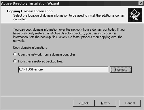
After the dcpromo command restores the directory information from the backup, an incremental update of the changes made since the media was created will be performed. Because of this, there still needs to be network connectivity throughout the DCPromo process, although the amount of replication required is significantly less. Because some DCPromo operations across slow WAN links have been known to take days and even weeks, this concept can dramatically help to deploy remote domain controllers.
Note
If the copy of the global catalog that has been backed up is older than the tombstone date for objects in the Active Directory (by default, 60 days from when an object was last validated as being active), this type of DCPromo will fail. This built-in safety mechanism prevents the introduction of lingering objects and also ensures that the information is relatively up to date and no significant incremental replication is required.
Previously, all groups in Active Directory had their membership listed as a multivalued attribute. This meant that any time the group membership was changed, the entire group membership needed to be re-replicated across the entire forest. Windows Server 2003 now includes an incremental replication approach to these objects, known as linked-value replication. This approach significantly reduces replication traffic associated with Active Directory.
Directly associated with this concept, Windows Server 2003 allows for the creation of domain controllers that cache universal group membership. This means that it no longer is necessary to place a global catalog server in each site. Any time a user utilizes a universal group, the membership of that group is cached on the local domain controller and is utilized when the next request comes for that group’s membership. This also lessens the replication traffic that would occur if a global catalog was placed in remote sites.
One of the main sources of replication traffic was discovered to be group membership queries—hence, the focus on fixing this problem. In Windows 2000 Active Directory, every time a client logged in, the client’s universal group membership was queried, requiring a global catalog to be contacted. This significantly increased login and query time for clients who did not have local global catalog servers. Consequently, many organizations stipulated that every site, no matter the size, must have a local global catalog server to ensure quick authentication and directory lookups. The downside of this was that replication across the directory was increased because every site received a copy of every item in the entire AD, even though only a small portion of those items was referenced by an average site.
Universal group caching solved this problem because only those groups that are commonly referenced by a site are stored locally, and requests for group replication are limited to the items in the cache. This helps to limit replication and keep domain logins speedy.
Universal group caching capability is established on a per-site basis through the following technique:
Open Active Directory Sites and Services.
Right-click NTDS Site Settings and choose Properties.
Check the Enable Universal Group Membership Caching box, as shown in Figure 7.16.
Click OK to save the changes.

Lingering objects, more affectionately known as zombies, are created when a domain controller is down for a period of time that is longer than the tombstone date for the deletion of items. When the domain controller is brought back online, it never receives the tombstone request and those objects always exist on the downed server. These objects could then be re-replicated to other domain controllers, arising from the dead as “zombies.” Windows Server 2003 has a mechanism for detecting lingering objects, isolating them and marking them for cleanup.
By default, intersite AD replication is compressed so as to reduce the bandwidth consumption required. The drawback to this technique is that extra CPU cycles are required on the domain controllers to properly compress and decompress this data. Windows Server 2003 allows designers the flexibility to turn off this compression, if an organization is short on processor time and long on bandwidth, so to speak.
Previously, in Windows 2000, any schema modifications would force a complete resynchronization of the global catalog with all domain controllers across an enterprise. This made it extremely ominous to institute any type of schema modifications because replication modifications would increase significantly following schema modifications. Windows Server 2003 environments do not have this limitation, however, and schema modifications are incrementally updated in the global catalog.
The Intersite Topology Generator (ISTG) portion of the KCC has been updated to allow AD environments to scale to site structures of up to 5,000 sites. Previous limitations to the Windows 2000 ISTG essentially kept AD implementations effectively limited to 1,000 sites. This improvement, however, is available only when all servers in your Active Directory environment are Windows Server 2003 systems and the forest functionality levels have been raised to Windows Server 2003 levels.
When the original structure of the Internet was taking shape, an addressing scheme was formulated to scale to a large number of hosts. From this thinking came the original design of the Internet Protocol, which included support for 232 addresses. The thinking at the time was that this would be more than enough addresses for all hosts on the Internet. This original design gave birth to the IP address structure that is common today, known as dotted-decimal format (such as 12.155.166.151). At the time, this address space filled the addressing needs of the Internet. However, it was quickly discovered that the range of addresses was inadequate, and stopgap measures such as Network Address Translation (NAT) were required to make more efficient use of the available addresses.
In addition to an inadequate supply of available addresses, the Internet Protocol version 4 (IPv4), as it is known, did not handle routing, IPSec, and QoS support very efficiently. The need for a replacement to IPv4 was evident.
In the early ‘90s, a new version of the Internet Protocol, known as Internet Protocol version 6 (IPv6), was formulated. This design had several functional advantages to IPv4, namely a much larger pool of addresses from which to choose (2128). This protocol is the future of Internet addressing, and it’s vitally important that an operating system support it.
Windows Server 2003 comes with a version of IPv6 ready to install, and is fully supported as part of the operating system. Given the complexity of IPv6, it will undoubtedly take some time before it is adopted widely, but understanding that the support exists is the first step towards deploying it widely.
To say that IPv6 is complicated is an understatement. Attempting to understand IPv4 has been difficult enough for network engineers; throw in hexadecimal 128-bit addresses and life becomes much more interesting. At a minimum, however, the basics of IPv6 must be understood as future networks will use the protocol more and more as time goes by.
IPv6 was written to solve many of the problems that persist on the modern Internet today. The most notable areas that IPv6 improved upon are the following:
Vastly improved address space—. The differences between the available addresses from IPv4 to IPv6 are literally exponential. Without taking into account loss because of subnetting and other factors, IPv4 could support up to 4,294,967,296 nodes. IPv6, on the other hand, supports up to 340,282,366,920,938,463,463,374,607,431,768, 211,456 nodes. Needless to say, IPv6 authors were thinking ahead and wanted to make sure that they wouldn’t run out of space again.
Improved network headers—. The header for IPv6 packets has been streamlined, standardized in size, and optimized. To illustrate, even though the address is four times as long as an IPv4 address, the header is only twice the size. In addition, by having a standardized header size, routers can more efficiently handle IPv6 traffic than they could with IPv4.
Native support for auto address configuration—. In environments where manual addressing of clients is not supported or desired, automatic configuration of IPv6 addresses on clients is natively built into the protocol. This technology is the IPv6 equivalent to the Automatic Private Internet Protocol Addressing (APIPA) feature added to Windows for IPv4 addresses.
Integrated support for IPSec and QoS—. IPv6 contains native support for IPSec encryption technologies and Quality of Service (QoS) network traffic optimization approaches, improving their functionality and expanding their capabilities.
An IPv6 address, as previously mentioned, is 128-bits long, as compared to IPv4’s 32-bit addresses. The address itself uses hexadecimal format to shorten the nonbinary written form. Take, for example, the following 128-bit IPv6 address written in binary:
111111101000000000000000000000000000000000000000000000000000000000000010000011
00001010011111111111111110010001000111111000111111
The first step in creating the nonbinary form of the address is to divide the number in 16-bit values:
1111111010000000 0000000000000000
0000000000000000 0000000000000000
0000001000001100 0010100111111111
1111111001000100 0111111000111111
Each 16-bit value is then converted to hexadecimal format to produce the IPv6 address:
FE80:0000:0000:0000:020C:29FF:FE44:7E3F
Luckily, the authors of IPv6 included ways of writing IPv6 addresses in shorthand by allowing for the removal of zero values that come before other values. For example, in the address listed previously, the 020C value becomes simply 20C when abbreviated. In addition to this form of shorthand, IPv6 allows continuous fields of zeros to be abbreviated by using a double colon. This can only occur once in an address, but can greatly simplify the overall address. The example used previously then becomes:
FE80:::20C:29FF:FE44:7E3F
Note
It’s futile to attempt to memorize IPv6 addresses, and converting hexadecimal to decimal format is often best accomplished via a calculator for most people. This has proven to be one of the disadvantages of IPv6 addressing for many administrators.
IPv6 addresses operate much in the same way as IPv4 addresses, with the larger network nodes indicated by the first string of values and the individual interfaces illustrated by the numbers on the right. By following the same principles as IPv4, a better understanding of IPv6 can be achieved.
Windows Server 2003 contains built-in support for IPv6, although it is not installed by default. Installation can take place through the command prompt by simply typing the following command:
Netsh interface ipv6 install
Support can also be added via the Network Components GUI interface by following these steps:
Go to Start, Control Panel.
Double-click Network Connections.
Right-click the LAN adapter to install IPv6 and choose Properties.
Click the Install button.
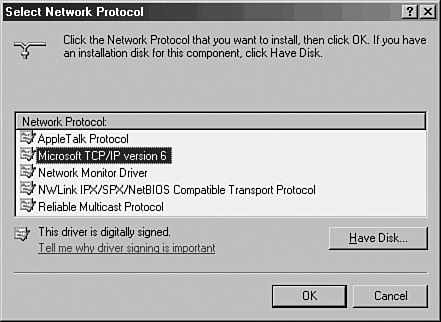
Select Protocol and then click the Add button.
Select Microsoft TCP/IP version 6, as illustrated in Figure 7.17.
Click OK and Close to finalize the installation.
Once installed, the IPv6 address will be configured in addition to the IPv4 address. To display both sets of addresses, type ipconfig /all at the command prompt, as illustrated in Figure 7.18.

The migration to IPv6 has been, and will continue to be, a slow and gradual process. In addition, support for IPv4 during and after a migration must still be considered for a considerable period of time. It is consequently important to understand the tools and techniques available to maintain both IPv4 and IPv6 infrastructure in place during a migration process.
When IPv6 is installed on Windows Server 2003, IPv4 support remains by default. This allows for a period of time in which both protocols are supported. Once migrated completely to IPv6, however, connectivity to IPv4 nodes that exist outside of the network (on the Internet, for example) must still be maintained. This support can be accomplished through the deployment of IPv6 tunneling technologies.
Windows Server 2003 tunneling technology consists of two separate technologies. The first technology, the Intrasite Automatic Tunnel Addressing Protocol (ISATAP), allows for intrasite tunnels to be created between pools of IPv6 connectivity internally in an organization. The second technology is known as 6to4, which provides for automatic intersite tunnels between IPv6 nodes on disparate networks, such as across the Internet. Deploying one or both of these technologies is a must in the initial stages of IPv6 industry adoption.
Understanding a new protocol implementation is not at the top of most people’s wish lists. In many cases, improvements such as improved routing, support for IPSec, no NAT requirements, and the like, are not enough to convince organizations to make the change. The process of change is inevitable, however, as the number of available nodes on the IPv4 model decreases. Consequently, it’s good to know that Windows Server 2003 is well prepared for the eventual adoption of IPv6.
Site topology in Windows Server 2003’s Active Directory has been engineered in a way to be adaptable to network environments of all shapes and sizes. Because so many WAN topologies exist, a subsequently large number of site topologies can be designed to match the WAN environment. Despite the variations, several common site topologies are implemented, roughly following the two design models detailed in the following sections. These real-world models detail how the Windows Server 2003 AD site topology can be used effectively.
CompanyA is a glass manufacturer with a central factory and headquarters located in Leuven, Belgium. Four smaller manufacturing facilities are located in Marseille, Brussels, Amsterdam, and Krakow. WAN traffic follows a typical hub-and-spoke pattern, as diagrammed in Figure 7.19.

CompanyA decided to deploy Windows Server 2003 to all its branch locations and allocated several domain controllers for each location. Sites in Active Directory were designated for each major location within the company and given names to match their physical location. Site links were created to correspond with the WAN link locations, and their replication schedules were closely tied with WAN utilization levels on the links themselves. The result was a Windows Server 2003 Active Directory site diagram that looks similar to Figure 7.20.

Both domain controllers in each site were designated as a preferred bridgehead server to lessen the replication load on the global catalog servers in the remote sites. However, the PDC Emulator in the main site was left off the list of preferred bridgehead servers to lessen the load on that server. Site link bridging was kept activated because there was no specific need to turn off this functionality.
This design left CompanyA with a relatively simple but robust replication model that it could easily modify at a future time as WAN infrastructure changes.
CompanyB is a mining and mineral extraction corporation that has central locations in Duluth, Charleston, and Cheyenne. Several branch locations are distributed across the continental United States. Its WAN diagram utilizes multiple WAN links, with various connection speeds, as diagrammed in Figure 7.21.
CompanyB recently implemented Windows Server 2003 Active Directory across its infrastructure. The three main locations consist of five Active Directory domain controllers and two global catalog servers. The smaller sites utilize one or two domain controllers for each site, depending on the size. Each server setup in the remote sites was installed using the Install from Media option because the WAN links were not robust enough to handle the site traffic that a full DCPromo operation would involve.
A site link design scheme, like the one shown in Figure 7.22, was chosen to take into account the multiple routes that the WAN topology provides. This design scheme provides for a degree of redundancy, as well, because replication traffic could continue to succeed even if one of the major WAN links was down.

Each smaller site was designated to cache universal group membership because bandwidth was at a minimum and CompanyB wanted to reduce replication traffic to the lowest levels possible, while keeping user logins and directory access prompt. In addition, traffic on the site links to the smaller sites was scheduled to occur only at hour intervals in the evening so that it did not interfere with regular WAN traffic during business hours.
Each domain controller in the smaller sites was designated as a preferred bridgehead server. In the larger sites, three domain controllers with extra processor capacity were designated as the preferred bridgehead servers for their respective sites to offload the extra processing load from the other domain controllers in those sites.
This design left CompanyB with a robust method of throttling replication traffic to its slower WAN links, but at the same time maintaining a distributed directory service environment that AD provides.
The separation of the directory model from the replication model in Windows Server 2003’s Active Directory allows domain designers to have full flexibility when designing replication topology and enables them to focus on replication efficiency. In addition, several new features in Windows Server 2003, such as IPv6 support, universal group caching, and Install from Media DC promotion, give the replication topology an even greater edge, and allow for the realization of improved replication times and reduced bandwidth.
Use the automatically generated connection objects that are created by the KCC, unless a specific reason exists to hard-code replication pathways.
Ensure that all your sites listed in DNS contain the appropriate SRV records.
Ensure that the schema version has been upgraded to R2 levels before installing Windows Server 2003 R2 on any domain controllers.
Use the repadmin and replmon tools to troubleshoot and validate Active Directory replication.
Consider using IPv6 for environments consisting of Windows XP and Windows Server 2003 and other IPv6-compliant devices.
Use IPv6 tunneling mechanisms such as ISATAP and 6to4 to provide long-term compatibility between IPv4 and IPv6.
Install the AD client on down-level 95/98/NT client machines (or replace them) to ensure connection to the closest DC.
Don’t turn off site link bridging unless you want to make your domain controller replication dependent on the explicit site links that you have established.