
Introduction to Transport-Level Security in Windows Server 2003
</objective> <objective> </objective> <objective> </objective> <objective> </objective> <objective>Configuring Simple IPSec Between Servers in a Windows Server 2003 Domain
</objective> </feature>In the past, networks were closed environments, insulated from each other and accessible only on internal segments. After time, a need developed to share information between these networks, and connections were established to transmit data from network to network. The transmission of this information was originally insecure, however, and, if intercepted, could easily be read by unauthorized persons. The need to secure this information was subsequently made a priority, and became a critical component of network infrastructure.
Over time the technology used to keep this information safe evolved along with the technology available to exploit and obtain unauthorized access to data. Despite these threats, intelligent design and configuration of secure transport solutions using Windows Server 2003 will greatly increase the security of a network. In many cases, they are absolutely required, especially for data sent across uncontrolled network segments, such as the Internet.
This chapter focuses on the mechanisms that exist to protect and encrypt information sent between computers on a network. New and improved transport security features in Windows Server 2003 are highlighted, and sample situations are detailed. IPSec, PKI, and VPN use is outlined and illustrated. In addition, specific server functionality such as that provided by Windows Server 2003’s Routing and Remote Access Server and Internet Authentication Server components is presented.
The very nature of interconnected networks requires that all information be sent in a format that can easily be intercepted by any client on a physical network segment. The data must be organized in a structured, common way so that the destination server can translate it into the proper information. This simplicity also gives rise to security problems, however, because intercepted data can easily be misused if it falls into the wrong hands.
The need to make information unusable if intercepted is the basis for all transport-level encryption. Considerable effort goes into both sides of this equation: Security specialists develop schemes to encrypt and disguise data, and hackers and other security specialists develop ways to forcefully decrypt and intercept data. The good news is that encryption technology has developed to the point that properly configured environments can secure their data with a great deal of success, as long as the proper tools are used. Windows Server 2003 offers much in the realm of transport-level security, and deploying some or many of the technologies available is highly recommended to properly secure important data.
Because even the most secure infrastructures are subject to vulnerabilities, deploying multiple layers of security on critical network data is recommended. If a single layer of security is compromised, the intruder will have to bypass the second or even third level of security to gain access to the vital data. For example, relying on a complex 128-bit “unbreakable” encryption scheme is worthless if an intruder simply uses social engineering to acquire the password or PIN from a validated user. Putting in a second or third layer of security, in addition to the first one, will make it that much more difficult for intruders to break through all layers.
Transport-level security in Windows Server 2003 uses multiple levels of authentication, encryption, and authorization to provide for an enhanced degree of security on a network. The configuration capabilities supplied with Windows Server 2003 allow for the establishment of several layers of transport-level security.
Encryption, simply defined, is the process of taking intelligible information and scrambling it so as to make it unintelligible for anyone except the user or computer that is the destination of this information. Without going into too much detail on the exact methods of encrypting data, the important point to understand is that proper encryption allows this data to travel across unsecured networks, such as the Internet, and be translated only by the designated destination. If packets of properly encrypted information are intercepted, they are worthless because the information is garbled. All mechanisms described in this chapter use some form of encryption to secure the contents of the data sent.
A common method of securing information sent across unsecured networks is to create a virtual private network (VPN), which is effectively a connection between two private nodes or networks that is secured and encrypted to prevent unauthorized snooping of the traffic between the two connections. From the client perspective, a VPN looks and feels just like a normal network connection between different segments on a network—hence the term virtual private network.
Data that is sent across a VPN is encapsulated, or wrapped, in a header that indicates its destination. The information in the packet is then encrypted to secure its contents. The encrypted packets are then sent across the network to the destination server, using what is known as a VPN tunnel.
The connection made by VPN clients across an unsecured network is known as a VPN tunnel. It is named as such because of the way it “tunnels” underneath the regular traffic of the unsecured network.
VPN tunnels are logically established on a point-to-point basis but can be used to connect two private networks into a common network infrastructure. In many cases, for example, a VPN tunnel serves as a virtual WAN link between two physical locations in an organization, all while sending the private information across the Internet. VPN tunnels are also widely used by remote users who log in to the Internet from multiple locations and establish VPN tunnels to a centralized VPN server in the organization’s home office. These reasons make VPN solutions a valuable asset for organizations, and one that can be easily established with the technologies available in Windows Server 2003 or extended even further with technologies that integrate directly with Windows Server 2003 VPN technology, such as the Internet Security and Acceleration (ISA) Server 2004 product.
Note
VPN tunnels can either be voluntary or compulsory. In short, voluntary VPN tunnels are created when a client, usually out somewhere on the Internet, asks for a VPN tunnel to be established. Compulsory VPN tunnels are automatically created for clients from specific locations on the unsecured network, and are less common in real-life situations than are voluntary tunnels.
The tunneling protocol is the specific technology that defines how data is encapsulated, transmitted, and unencapsulated across a VPN connection. Varying implementations of tunneling protocols exist, and correspond with different layers of the Open System Interconnection (OSI) standards-based reference model. The OSI model is composed of seven layers, and VPN tunneling protocols use either Layer 2 or Layer 3 as their unit of exchange. Layer 2, a more fundamental network layer, uses a frame as the unit of exchange, and Layer 3 protocols use a packet as a unit of exchange.
The most common Layer 2 VPN protocols are the Point-to-Point Tunneling Protocol (PPTP) and the Layer 2 Tunneling Protocol (L2TP), both of which are fully supported protocols in Windows Server 2003.
Both PPTP and L2TP are based on the well-defined Point-to-Point Protocol (PPP) and are consequently accepted and widely used in VPN implementations. L2TP is the preferred protocol for use with VPNs in Windows Server 2003 because it incorporates the best of PPTP, with a technology known as Layer 2 Forwarding. L2TP allows for the encapsulation of data over multiple network protocols, including IP, and can be used to tunnel over the Internet. The payload, or data to be transmitted, of each L2TP frame can be compressed, as well as encrypted, to save network bandwidth.
Both PPTP and L2TP build on a suite of useful functionality that was introduced in PPP, such as user authentication, data compression and encryption, and token card support. These features, which have all been ported over to the newer implementations, provide for a rich set of VPN functionality.
Windows Server 2003 uses an additional layer of encryption and security by utilizing IP Security (IPSec), a Layer 3 encryption protocol, in concert with L2TP in what is known, not surprisingly, as L2TP/IPSec. IPSec allows for the encryption of the L2TP header and trailer information, which is normally sent in clear text. This also has the added advantage of dual-encrypting the payload, adding an additional level of security into the mix.
L2TP/IPSec has some distinct advantages over standard L2TP, namely the following:
L2TP/IPSec allows for data authentication on a packet level, allowing for verification that the payload was not modified in transit, as well as the data confidentiality that is provided by L2TP.
Dual-authentication mechanisms stipulate that both computer-level and user-level authentication must take place with L2TP/IPSec.
L2TP packets intercepted during the initial user-level authentication cannot be copied for use in offline dictionary attacks to determine the L2TP key because IPSec encrypts this procedure.
An L2TP/IPSec packet contains multiple, encrypted header information and the payload itself is deeply nested within the structure. This allows for a great deal of transport-level security on the packet itself.
Users who connect via a VPN connection need to be authenticated through a mechanism that stores the users’ associated username and password information in a centralized location. Traditional VPN solutions utilized a directory on a Remote Authentication Dial-in User Service (RADIUS) server, which authenticated users based on their remote access usernames and passwords. Often, however, these user accounts were different from the domain user accounts, and administration of the two environments was complicated because multiple passwords and user accounts needed to be administered.
Windows Server 2003 simplifies the VPN authentication process by utilizing the Internet Authentication Service (IAS) installed on a Windows Server 2003 server to provide for RADIUS-based authentication of users using domain Active Directory usernames and passwords.
You can install and configure IAS on a Windows Server 2003 server by following these steps:
Choose Start, Control Panel, Add or Remove Programs.
Click Add/Remove Windows Components.
Select the Networking Services component (don’t check it) and click the Details button.
Check the Internet Authentication Service box, as illustrated in Figure 13.1, and click OK.
Click Next to continue. The installation will proceed.
Click Finish at the Completion screen.

Depending on the administrative credentials used to install IAS, you may need to register it in Active Directory following installation if it will be used to authenticate users who exist in AD for VPN and dial-up access. To perform this function, follow these steps:
Choose Start, All Programs, Administrative Tools, Internet Authentication Service.
Right-click Internet Authentication Service (Local) and choose Register Server in Active Directory.
If IAS was already registered in AD, acknowledgment of that fact will be displayed. Otherwise, a success dialog box will be displayed, indicating the proper registration of IAS with AD.
The Routing and Remote Access Server (RRAS), available for installation on Windows Server 2003, effectively provides servers with VPN functionality through the use of L2TP/IPSec and PPTP authentication. RRAS servers can be established to serve on one end or on both ends of a VPN conversation, and work in concert with IAS to authenticate VPN users.
RRAS in Windows Server 2003 adds key functionality such as network load balancing (NLB) support and increased performance; it also integrates the Internet Connection Firewall (ICF) component into RRAS.
Note
While Windows Server 2003 contains robust VPN support, additional VPN functionality can be obtained by extending Windows Server 2003 with the Internet Security and Acceleration (ISA) Server 2004/2006 product available from Microsoft. ISA Server extends the RRAS Service to allow for rule-based access control and application layer inspection of VPN traffic. For more information, reference Sams Publishing’s ISA Server 2004 Unleashed and/or ISA Server 2006 Unleashed titles.
The Routing and Remote Access Server can be installed on a Windows Server 2003 computer by using the Configure Your Server (CYS) Wizard, as described in the following steps:
Open the Configure Your Server Wizard (Start, All Programs, Administrative Tools, Configure Your Server Wizard).
Click Next at the Welcome screen.
Click Next at the Preliminary Steps screen. CYS will then check the network settings of the server.
Select Remote Access/VPN Server, as illustrated in Figure 13.2, and click Next to continue.
At the Summary screen, click Next to continue. CYS will then install the component and automatically invoke the RRAS Setup Wizard.
Click Next at the RRAS Setup Wizard Welcome screen.
The subsequent screen is critical because you can define specific RRAS functionality. RRAS can be set up for remote access VPN or VPN with Network Address Translation (NAT) access. In addition, it can be set up as one end of a VPN between two private networks. Finally, a custom configuration can be chosen, as illustrated in Figure 13.3. In this example, choose Remote Access and click Next to continue.
Check the VPN box at the following screen and click Next to continue.
At the finalization screen, click Finish to finalize the RRAS settings chosen.
A final confirmation box will indicate that RRAS has been installed and will ask whether the service should be started. Click Yes to start the service and complete the installation and then click Finish to close the CYS Wizard.


The RRAS server is the key to implementing the VPN options described in this chapter and can be used to provide for any of the options listed here.
The term public key infrastructure (PKI) is often loosely thrown around, but is not often thoroughly explained. PKI, in a nutshell, is the collection of digital certificates, registration authorities, and certificate authorities that verify the validity of each participant in an encrypted network. Effectively, a PKI itself is simply a concept that defines the mechanisms that ensure that the user who is communicating with another user or computer on a network is who he says he is. PKI implementations are widespread and are becoming a critical component of modern network implementations. Windows Server 2003 fully supports the deployment of multiple PKI configurations, as defined in the following sections.
PKI deployments can range from simple to complex, with some PKI implementations utilizing an array of smartcards and certificates to verify the identity of all users with a great degree of certainty. Understanding the capabilities of PKI and choosing the proper deployment for an organization are subsequently a must.
Encryption techniques can primarily be classified as either symmetrical or asymmetrical. Symmetrical encryption requires that each party in an encryption scheme hold a copy of a private key, which is used to encrypt and decrypt information sent between the two parties. The problem with private key encryption is that the private key must somehow be transmitted to the other party without it being intercepted and used to decrypt the information.
Public key, or asymmetrical, encryption uses a combination of two keys, which are mathematically related to each other. The first key, the private key, is kept closely guarded and is used to encrypt the information. The second key, the public key, can be used to decrypt the information. The integrity of the public key is ensured through certificates, which will be explained in depth in following sections of this chapter. The asymmetric approach to encryption ensures that the private key does not fall into the wrong hands and only the intended recipient will be able to decrypt the data.
A certificate is essentially a digital document that is issued by a trusted central authority and is used by the authority to validate a user’s identity. Central, trusted authorities such as VeriSign are widely used on the Internet to ensure that software from Microsoft, for example, is really from Microsoft, and not a virus in disguise.
Certificates are used for multiple functions, such as the following:
Secure email
Web-based authentication
IP Security (IPSec)
Code signing
Certification hierarchies
Certificates are signed using information from the subject’s public key, along with identifier information such as name, email address, and so on, and a digital signature of the certificate issuer, known as the Certificate Authority (CA).
Windows Server 2003 includes a built-in Certificate Authority (CA) known as Certificate Services. Certificate Services can be used to create certificates and subsequently manage them; it is responsible for ensuring their validity. Certificate Services is often used in Windows Server 2003 if there is no particular need to have a third-party verify an organization’s certificates. It is common practice to set up a standalone CA for network encryption that requires certificates only for internal parties. Third-party certificate authorities such as VeriSign are also extensively used but require an investment in individual certificates.
Certificate Services for Windows Server 2003 can be installed as one of the following CA types:
Enterprise Root Certification Authority—. The enterprise root CA is the most trusted CA in an organization and should be installed before any other CA. All other CAs are subordinate to an enterprise root CA.
Enterprise Subordinate Certification Authority—. An enterprise subordinate CA must get a CA certificate from an enterprise root CA but can then issue certificates to all users and computers in the enterprise. These types of CAs are often used for load balancing of an enterprise root CA.
Standalone Root Certification Authority—. A standalone root CA is the root of a hierarchy that is not related to the enterprise domain information. Multiple standalone CAs can be established for particular purposes.
Standalone Subordinate Certification Authority—. A standalone subordinate CA receives its certificate from a standalone root CA and can then be used to distribute certificates to users and computers associated with that standalone CA.
To install Certificate Services on Windows Server 2003, follow these steps:
Choose Start, Control Panel, Add or Remove Programs.
Click Add/Remove Windows Components.
Check the Certificate Services box.
A warning dialog box will be displayed, as illustrated in Figure 13.4, indicating that the computer name or domain name cannot be changed after you install Certificate Services. Click Yes to proceed with the installation.
Click Next to continue.
The following screen, shown in Figure 13.5, allows you to create the type of CA required. Refer to the preceding list for more information about the different types of CAs that you can install. In this example, choose Enterprise Root CA and click Next to continue.
Enter a common name for the CA—for example,
CompanyABC Enterprise Root CA.Enter the validity period for the Certificate Authority and click Next to continue. The cryptographic key will then be created.
Enter a location for the certificate database and then database logs. The location you choose should be secure, to prevent unauthorized tampering with the CA. Click Next to continue. Setup will then install the CA components.
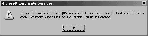
If IIS is not installed, a prompt will be displayed, as shown in Figure 13.6, indicating that Web Enrollment will be disabled until you install IIS. If this box is displayed, click OK to continue.
Click Finish after installation to complete the process.


A robust solution for a public key infrastructure network can be found in the introduction of smartcard authentication for users. Smartcards are plastic cards that have a microchip embedded in them; this chip allows them to store unique information in each card. User login information, as well as certificates installed from a CA server, can be placed on a smartcard. When a user needs to log in to a system, she places the smartcard in a smartcard reader or simply swipes it across the reader itself. The certificate is read, and the user is prompted only for a PIN, which is uniquely assigned to each user. After the PIN and the certificate are verified, the user can log in to the domain.
Smartcards have obvious advantages over standard forms of authentication. It is no longer possible to simply steal or guess someone’s username and password in this scenario as the username can be entered only via the unique smartcard. If stolen or lost, the smartcard can be immediately deactivated and the certificate revoked. Even if a functioning smartcard were to fall into the wrong hands, the PIN would still need to be used to properly access the system. Smartcards are fast becoming a more accepted way to integrate the security of certificates and PKI into organizations.
Just as transport information can be encrypted via certificates and public key infrastructure, so too can the NT File System (NTFS) on Windows Server 2003 be encrypted to prevent unauthorized access. The Encrypting File System (EFS) option in Windows Server 2003 allows for this type of functionality and improves on the Windows 2000 EFS model by allowing offline folders to maintain encryption sets on the server. EFS is advantageous, particularly for laptop users who tote around sensitive information. If the laptop or hard drive is stolen, the file information is worthless because it is scrambled and can be unscrambled only with the proper key. EFS is proving to be an important part in PKI implementations.
Windows Server 2003’s Active Directory component can use the PKI infrastructure, which utilizes trusts between foreign non-Microsoft Kerberos realms and Active Directory. The PKI infrastructure serves as the authentication mechanism for security requests across the cross-realm trusts that can be created in Active Directory.
IP Security (IPSec), mentioned briefly in previous sections, is essentially a mechanism for establishing end-to-end encryption of all data packets sent between computers. IPSec operates at Layer 3 of the OSI model and subsequently uses encrypted packets for all traffic between members.
IPSec is often considered to be one of the best ways to secure the traffic generated in an environment, and is useful for securing servers and workstations both in high-risk Internet access scenarios and also in private network configurations for an enhanced layer of security.
The basic principle of IPSec is this: All traffic between clients—whether initiated by applications, the operating system, services, and so on—is entirely encrypted by IPSec, which then puts its own header on each packet and sends the packets to the destination server to be decrypted. Because every piece of data is encrypted, this prevents electronic eavesdropping, or listening in on a network in an attempt to gain unauthorized access to data.
Several functional IPSec deployments are available, and some of the more promising ones are actually built into the network interface cards (NICs) of each computer, performing encryption and decryption without the operating system knowing what is going on. Aside from these alternatives, Windows Server 2003 includes a robust IPSec implementation by default, which can be configured to use a PKI certificate network or the built-in Kerberos authentication provided by Active Directory on Windows Server 2003.
IPSec in Windows Server 2003 provides for the following key functionality that, when combined, provides for one of the most secure solutions available for client/server encryption:
Data Privacy—. All information sent from one IPSec machine to another is thoroughly encrypted by such algorithms as 3DES, which effectively prevent the unauthorized viewing of sensitive data.
Data Integrity—. The integrity of IPSec packets is enforced through ESP headers, which verify that the information contained within an IPSec packet has not been tampered with.
Anti-Replay Capability—. IPSec prevents streams of captured packets from being resent, known as a “replay” attack, blocking such methods of obtaining unauthorized access to a system by mimicking a valid user’s response to server requests.
Per-Packet Authenticity—. IPSec utilizes certificates or Kerberos authentication to ensure that the sender of an IPSec packet is actually an authorized user.
NAT Transversal—. Windows Server 2003’s implementation of IPSec now allows for IPSec to be routed through current NAT implementations, a concept that will be defined more thoroughly in the following sections.
Diffie-Hellman 2048-Bit Key Support—. Virtually unbreakable Diffie-Hellman 2048-bit key lengths are supported in Windows Server 2003’s IPSec implementation, essentially assuring that the IPSec key cannot be broken.
As previously mentioned, IPSec in Windows Server 2003 now supports the concept of Network Address Translation Transversal (NAT-T). Understanding how NAT-T works first requires a full understanding of the need for NAT itself.
Network Address Translation (NAT) was developed simply because not enough IP addresses were available for all the clients on the Internet. Because of this, private IP ranges were established (10.x.x.x, 192.168.x.x, and so on) to allow all clients in an organization to have a unique IP address in their own private space. These IP addresses were designed to not route through the public IP address space, and a mechanism was needed to translate them into a valid, unique public IP address.
NAT was developed to fill this role. It normally resides on firewall servers or routers to provide for NAT capabilities between private and public networks. RRAS for Windows Server 2003 provides NAT capabilities as well.
Because the construction of the IPSec packet does not allow for NAT addresses, IPSec traffic has, in the past, simply been dropped at NAT servers, as there is no way to physically route the information to the proper destination. This posed major barriers to the widespread implementation of IPSec because many of the clients on the Internet today are addressed via NAT.
NAT Transversal, which is a new feature in Windows Server 2003’s IPSec implementation, was jointly developed as an Internet standard by Microsoft and Cisco Systems. NAT-T works by sensing that a NAT network will need to be transversed and subsequently encapsulating the entire IPSec packet into a UDP packet with a normal UDP header. NAT handles UDP packets flawlessly, and they are subsequently routed to the proper address on the other side of the NAT.
NAT Transversal works well but requires that both ends of the IPSec transaction understand the protocol so as to properly pull the IPSec packet out of the UDP encapsulation. With the latest IPSec client and server, NAT-T becomes a reality and is positioned to make IPSec into a much bigger success than it is today.
Note
NAT-T was developed to keep current NAT technologies in place without changes. However, some implementations of NAT have attempted to make IPSec work natively across the translation without NAT-T. Disabling this functionality with NAT-T may be wise, however, because it may interfere with IPSec since both NAT-T and the NAT firewall will be attempting to overcome the NAT barrier.
IPSec is built into Windows Server 2003 machines and is also available for clients. In fact, basic IPSec functionality can easily be set up in an environment that is running Windows Server 2003’s Active Directory because IPSec can utilize the Kerberos authentication functionality in lieu of certificates. Subsequently, it is a fairly straightforward process to install and configure IPSec between servers and workstations, and should be considered as a way to further implement additional security in an environment.
The procedure outlined in the following sections illustrates the setup of a simple IPSec policy between a Web server and a client on a network. In this example, the Web server is SERVER7 and the client is CLIENT2.
To view the current status of any IPSec policies, including the ones that will be created in this procedure, the IPSec Security Monitor MMC snap-in on SERVER7 must be opened. The MMC snap-in can be installed and configured by following these steps:
Choose Start, Run and type
mmcinto the Run dialog box. Click OK when complete.In MMC, choose File, Add/Remove Snap-in.
Click the Add button to install the snap-in.
Scroll down and select IP Security Monitor; then click the Add button followed by the Close button.
The IP Security Monitor MMC snap-in should now be visible, as illustrated in Figure 13.7. Click OK.
In MMC, expand to Console RootIP Security MonitorSERVER7.
Right-click on SERVER7 and choose Properties.
Change the auto refresh setting from 45 seconds to 5 seconds or less. Click OK when finished. You can then use the MMC IP Security Monitor console to view IPSec data.

Default IPSec policies are enabled on Windows Server 2003 and newer clients. To access these settings, follow this procedure on SERVER7:
The following three default IPSec policies available allow for different degrees of IPSec enforcement:
Server (Request Security)—. In this option, the server requests but does not require IPSec communications. Choosing this option allows the server to communicate with other non-IPSec clients. It is recommended for organizations with lesser security needs or those in the midst of, but not finished with, an implementation of IPSec because it can serve as a stop-gap solution until all workstations are IPSec configured. This option does allow for some of the enhanced security of IPSec but without the commitment to all communications in IPSec.
Client (Respond Only)—. The Client option allows the configured machine to respond to requests for IPSec communications.
Secure Server (Require Security)—. The most secure option is the Require Security option, which stipulates that all network traffic be encrypted with IPSec. This policy effectively locks out other types of services that are not running IPSec, and should be set only if a full IPSec plan has been put into place.
CLIENT2 will likewise need to be configured with a default IPSec policy, in a similar fashion to the server policy defined in the preceding section. To configure the client on Windows XP, follow these steps:
Choose Start, All Programs, Administrative Tools, Local Security Policy. (Administrative Tools must be enabled in the Task Manager view settings.)
Navigate to Security SettingsIP Security Policies on Local Computer.
Right-click Client (Respond Only) and select Assign, as illustrated in Figure 13.8.

After the local IPSec policies are enabled on both CLIENT2 and SERVER7, IPSec communications can take place. To test this, either ping the server from the client desktop, or perform other network tests, such as accessing SERVER7’s Web page or file shares.
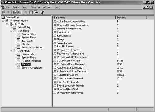
A quick look at the IP Security Monitor that was established in MMC on SERVER7 shows that IPSec traffic has been initialized and is logging itself, as you can see in Figure 13.9.
In addition to using the IP Security Monitor to log IPSec traffic, the Security log in the Event Viewer on SERVER7 can be used to check for IPSec events. Filter specifically for Event ID 541, which indicates successful IPSec communications, as shown in Figure 13.10.

These default IPSec policies are useful in establishing ad hoc IPSec between clients on a network, but are limited in their scope. Proper planning of an enterprise IPSec implementation is necessary to effectively secure an entire environment using custom IPSec policies.
In today’s interconnected networks, transport-level security is a major, if not one of the most important, security consideration for any organization. Securing the communications between users and computers on a network is vital, and in some cases required by law. Windows Server 2003 builds on the strong security base of Windows 2000 to include support for transport-level security mechanisms such as VPNs, IPSec, and PKI certificate–based infrastructures. Proper configuration and utilization of these tools can effectively lock down an organization’s transmission of data and ensure that it is used only by the proper individuals.
To secure a networking environment, deploy some or many of the transport-level security technologies available.
Because even the most secure infrastructures are subject to vulnerabilities, it is recommended to deploy multiple layers of security on critical network data.
L2TP is the preferred protocol for use with VPNs in Windows Server 2003 because it provides for the encapsulation of data over multiple network protocols.
Implement IPSec to secure the traffic generated in an environment and for securing servers and workstations both in high-risk Internet access scenarios and also in private network configurations.