
Chapter 4. Data modeling: End to end 97
4.3.1 A starting point: The physical data model
Here we aim to create a logical data model of the target OLAP data warehouse
by first creating a physical data model of the OLTP production database. In our
example, this is a physical data model of the IWHPRD82 database on our lab
systems. It is worth noting that you can, as an alternative, always start with a new
blank logical data model in InfoSphere Data Architect.
To start this process, perform these steps:
1. Start InfoSphere Data Architect and create a workbench storage area, if one
has not already been assigned.
2. Create a new Data Project to store your work by selecting from the main
menu File New Data Design Project.
3. Within the wizard, give the new project a name, for example, Redbooks
Model, then select Finish. This creates a new project within the Data Project
Explorer window.
Note that a number of subsections under the main project name have been
created automatically. These are directories on the file system within the
workbench area. Those of interest to us are the Data Diagram and Data
Model directories, which currently are empty.
4. Within the Project Explorer area, right-click the Data Model directory and
select New Physical Data Model.
5. In the opened wizard, edit the file name “Physical Data Model” to be
something more meaningful. We use IWHPRD82-CSTINSIGHT, which is the
Our examples: The examples detailed in this section are all based on the
schemas and tables contained in the IWHPRD82 database hosted within the
InfoSphere Warehouse VMware image detailed in 3.3, “Example architecture
used in this book” on page 77. This is a demonstration database that is
created from the models and schemas supplied as part of the InfoSphere
Warehouse Customer Insight Pack.
As such, the implementation of the database has already been developed
from a dimensioned logical star schema model. Therefore, for our exercises in
this chapter, we have to apply a small element of artistic license. As an
example, the modeling process normally starts with a physical model of a
OLTP production database that we did not have, so we started with a physical
model of our OLAP database.
98 Solving Operational Business Intelligence with InfoSphere Warehouse Advanced Edition
name of our database plus the name of the schema of most interest to us.
Then select Create from reverse engineering. Click Next.
In our case, we reverse-engineer our model from a live database. However, it
is also possible to use a DDL file of the source database produced by the
db2look utility.
6. Within the next wizard panel, select Database. Click Next.
7. From the list of databases shown, select the source that is going to act as the
base for your model. In our example, it is IWHPRD82. Click Next.
8. The next wizard panel lists all the schemas discovered from the selected
database. Any of those listed can be selected to be part of the model. In our
example, we are interested in CSTINSIGHT. Click Next.
9. The wizard then lists the database elements that are required to be pulled into
the physical model. At this point the defaults are sufficient for our needs, so
click Next.
10.At this point we are asked if we want to produce an Overview diagram, and
whether it is to contain the relationships. Select Yes to the Overview diagram,
and click Finish.
The final process of actually creating the physical data model might take a
few minutes while the tool interrogates the live database and records those
elements of the database needed in the model. On completion, the model is
added under the Data Model directory of the Project Explorer panel and
opened to allow browsing of the database elements.


100 Solving Operational Business Intelligence with InfoSphere Warehouse Advanced Edition
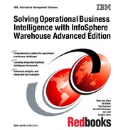
Opening the overview diagram (using a double-click) at this stage displays a
busy and confusing view because it contains all the tables within the selected
schema. See Figure 4-10.
Figure 4-10 Physical model within InfoSphere Data Architect
Before moving forward to develop our logical data model, it is worth taking the
time to explain what a “physical data model” actually is.
A physical data model is central to all the development tasks required to
implement an InfoSphere Warehouse. It contains the metadata for the
representation of an actual physical database. This include schemas, tables,
columns, views, stored procedures, table spaces, users, and all the elements
that make up a relational database. The physical data models are not limited to
simply the representation of DB2 databases; they can also be used to represent
a number of relational databases of different vendors such as Informix, Derby,
MySQL, and so on.
A physical data model can also be used during the modeling process for OLAP
objects to represent items such as cubes, fact, and dimensional tables, as is
demonstrated later in this chapter.

Chapter 4. Data modeling: End to end 101
Within IBM InfoSphere Data Architect, a physical data model is implemented as
an entity relationship model, with either information engineering (IE) or unified
modeling language (UML) notation. Figure 4-11 demonstrates the database
elements represented within a physical data model.
Figure 4-11 Relational database elements represented within a physical data model
Physical data model files can be exchanged between IBM InfoSphere Data
Architect and other client development tools such as IBM Data Studio and IBM
Design Studio.
For more details about the development, and implementations around physical
data models, refer to InfoSphere Warehouse: A Robust Infrastructure for
Business Intelligence, SG24-7813.
..................Content has been hidden....................
You can't read the all page of ebook, please click here login for view all page.