Chapter 8
Number Systems
8.1 Introduction
In everyday life, we use the decimal number system (base, or radix, 10), which allows the creation of numbers with digits in the set: 0, 1, 2, 3, 4, 5, 6, 7, 8, 9. The ten possible digits are combined to create integer and real numbers. However, base 10 is not the only number system. Digital circuits and systems use the binary (base, or radix, 2) number system, which allows for the creation of numbers with digits in the set: 0, 1.
The 0 and 1 numbers are logic levels (0 = logic 0, 1 = logic 1), which are created by voltages in a circuit:
• In positive logic, 0 is formed by a low voltage level, and 1 is formed by a high voltage level.
• In negative logic, 0 is formed by a high voltage level, and 1 is formed by a low voltage level.
In this text, only positive logic will be used and will use the voltage levels shown in Table 8.1.
Table 8.1 Typical voltage levels representing positive logic
| Logic level | +5V logic | +3.3V logic |
| 0 | +5.0V | +3.3V |
| 1 | 0V | 0V |
Decimal and binary number systems are only two of four number systems used in digital circuits and systems:
At some point in the design and analysis of a digital circuit, it will be necessary to convert between the different number systems to view and manipulate values propagating through the design. Such conversion is typically undertaken to aid the interpretation and understanding of the design operation.
In addition, a binary number can have different meanings as different binary coding can be chosen for different design requirement. The main binary coding schemes used are:
Unsigned binary numbers are used to represent positive numbers only. Signed binary numbers are used to represent positive and negative numbers that are coded to allow arithmetic using either 1s complement or 2’s complement notation. Twos complement notation is more commonly used and will be considered in this text. Gray code allows for a one-bit change when moving from one value to the next (or previous) value. BCD provides a simple conversion between binary and decimal numbers.
All four binary coding schemes are fully discussed in the following sections.
8.2 Decimal–Unsigned Binary Conversion
The conversion between decimal and binary involves identifying the particular decimal value for the particular binary code (or vice versa). Both decimal-to-binary and binary-to-decimal conversion is common and a binary number will be needed to represent each decimal number. If both the decimal and binary numbers are unrestricted in size, then an exact conversion is possible.
In unsigned (or straight) binary, the numbers represented by the binary code will be positive numbers only. Each digit in the binary number will contribute to the magnitude of the value. For example, consider the decimal value 810. In unsigned binary, this is represented by 10002. Each digit in the decimal number has a value in the set of (0, 1, 2, 3, 4, 5, 6, 7, 8, 9). Each digit in the binary number is in the set of (0, 1). A binary digit is referred to as a bit (binary digit).
The magnitude of the decimal number is the sum of the product of the value of each digit in the number (d) and its position (n). The position immediately to the left of the decimal point is position zero (0). The value of the digit has a weight of 2n where n is the position number. Moving left from position 0 (in the integer part of the number), the position increments by 1. Moving right from position zero (into the fractional part of the number), the position decrements by 1. Therefore, the magnitude of the number is given by:

Here, the decimal number is written as:
![]()
Some example decimal numbers are:
The binary number is a base 2 number whose magnitude is the sum of the product of the value of each digit in the number (b) and its position (n). Moving left from position 0 (in the integer part of the number), the position increments by 1. The value of the digit has a weight of 2n where n is the position number. Moving right from position zero (into the fractional part of the number), the position decrements by 1. This allows the creation of numbers with digits in the set: 0, 1. Therefore, in general the magnitude of the number (as a decimal number) is given by:

Here, the binary number is written as bnbn−1 bn−2 … b0.b −1 …. b−n. Some example binary numbers are:

The decimal number equivalent for a binary number can be created by taking the binary number and calculating its magnitude (as a decimal number):

Some example binary numbers are:
The binary number equivalent of a decimal number is created by dividing the decimal number by 2 until the result of the division is 0. The remainder of the total division forms the binary number digits, the remainder from the first division forms the least significant bit (LSB) of the binary number, and the remainder from the last division forms the most significant bit (MSB) of the binary number.
Consider the number 810. The conversion procedure is shown in Table 8.2.
Table 8.2 Conversion procedure for number 810
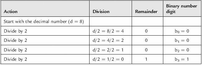
The binary number can be read as: 810 = (b3b2b1b0)2 = 10002.
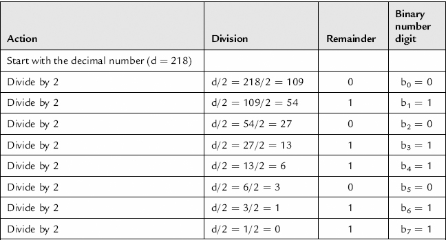
Consider now the number 21810. The conversion procedure is shown in Table 8.3.
Table 8.3 Conversion procedure for number 21810
8.3 Signed Binary Numbers
Unsigned (or straight) binary numbers are used when the operations use only positive numbers and the result of any operations is a positive number. However, in many cases, both the number and the result can be either positive or negative, and the unsigned binary number system cannot be used. The two coding schemes used to achieve this are the 1’s complement and 2’s complement.
The 1’s complement of a number is obtained by changing (or inverting) each of the bits in the binary number (0 becomes a 1 and a 1 becomes a 0):
The 2’s complement is formed by adding 1 to the 1’s complement:
The MSB of the binary number is used to represent the sign (0 = positive, 1 = negative) of the number, and the remainder of the number represents the magnitude. It is therefore essential that the number of bits used is sufficient to represent the required range, as shown in Table 8.4. Here, only integer numbers are considered.
Table 8.4 Number range
| Number of bits | Unsigned binary range | 2’s complement number range |
| 4 | 010 to +1510 | −810 to +710 |
| 8 | 010 to +25510 | −12810 to +12710 |
| 16 | 010 to +65,53510 | −32,76810 to +32,76710 |
Two’s complement number manipulation is as follows:
• To create a positive binary number from a positive decimal number, create the positive binary number for the magnitude of the decimal number where the MSB is set to 0 (indicating a positive number).
• To create a negative binary number from a negative decimal number, create the positive binary number for the magnitude of the decimal number where the MSB is set to 0 (indicating a positive number), then invert all bits and add 1 to the LSB. Ignore any overflow bit from the binary addition.
• To create a negative binary number from a positive binary number, where the MSB is set to 0 (indicating a positive number), invert all bits and add 1 to the LSB. Ignore any overflow bit from the binary addition.
• To create a positive binary number from a negative binary number, where the MSB is set to 1 (indicating a negative number), invert all bits and add 1 to the LSB. Ignore any overflow bit from the binary addition.
The 2’s complement number coding scheme is widely used in digital circuits and system design and so will be explained further. Table 8.5 shows the binary representations of decimal numbers for a four-bit binary number. In the unsigned binary number coding scheme, the binary number represents a positive decimal number from 010 to +1510. In the 2’s complement number coding scheme, the decimal number range is −810 to +710.
Table 8.5 Decimal to binary conversion
| Decimal number | 4-bit unsigned binary number | 4-bit 2’s complement signed binary number |
| +15 | 1111 | — |
| +14 | 1110 | — |
| +13 | 1101 | — |
| +12 | 1100 | — |
| +11 | 1011 | — |
| +10 | 1010 | — |
| +9 | 1001 | — |
| +8 | 1000 | — |
| +7 | 0111 | 0111 |
| +6 | 0110 | 0110 |
| +5 | 0101 | 0101 |
| +4 | 0100 | 0100 |
| +3 | 0011 | 0011 |
| +2 | 0010 | 0010 |
| +1 | 0001 | 0001 |
| 0 | 0000 | 0000 |
| −1 | — | 1111 |
| −2 | — | 1110 |
| −3 | — | 1101 |
| −4 | — | 1100 |
| −5 | — | 1011 |
| −6 | — | 1010 |
| −7 | — | 1001 |
| −8 | — | 1000 |
In this, the most negative 2’s complement number is 110 greater in magnitude than the most positive 2’s complement number. The number range for an n-bit number is: −2N to +(2N – 1).
Addition and subtraction are undertaken by addition and if necessary inversion (creating a negative number from a positive number and vice versa). Table 8.6 shows the cases for addition and subtraction of two numbers (A and B). It is essential to ensure that the two numbers have the same number of bits, the MSB represents the sign of the binary number, and the number of bits used is sufficient to represent the range of possible inputs and the range of possible outputs.
Table 8.6 2’s complement addition and subtraction

Figure 8.1 shows an arrangement where two inputs are either added or subtracted, depending on the logic level of a control input. This arrangement requires an adder, a complement (a logical inversion of the inputs bits and add 1, disregarding any overflow), and a digital switch (multiplexer).

Figure 8.1 Addition and subtraction (2’s complement arithmetic)
Input numbers in the range −810 to +710 are represented by four bits in binary. However, the range for the result of an addition is −1610 to +1410, and the range for the result of a subtraction is −1510 to +1510. The result requires five bits in binary to represent the number range (one bit more than the number of bits required to represent the inputs), so the number of bits to represent the inputs will be increased by one bit before the addition or subtraction:
• In an unsigned binary number, to increase the wordlength (number of bits) by one bit, append a 0 to the number as the new MSB:
• In a 2’s complement number, to increase the word length by one bit, then append a bit with the same value as the original MSB to the number as the new MSB:
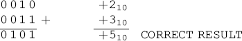
Consider the addition of +210 to +310 using 2’s complement numbers. The result should be +510. The two input numbers can be represented by three bits, but if 3-bit addition is undertaken, the result will be in error:

If, however, the input word length is increased by one bit, then the addition is undertaken, the result becomes:
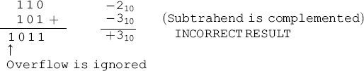
Consider the subtraction of +310 from −210. The result should be −510. The two input numbers can be represented by three bits, but if 3-bit addition is undertaken, then the result will be in error:
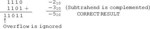
If, however, the input word length is increased by one bit, then the addition is undertaken, the result becomes:
8.4 Gray Code
The Gray code provides a binary code that changes by one bit only when it changes from one value to the next.
The Gray code and the decimal number equivalent of the binary number (in unsigned binary) are shown in Table 8.7. This is no longer a straight binary count sequence.
Table 8.7 Gray code
| Decimal number | 4-bit Gray code (d3d2d1d0) |
| 0 | 0000 |
| 1 | 0001 |
| 3 | 0011 |
| 2 | 0010 |
| 6 | 0110 |
| 7 | 0111 |
| 5 | 0101 |
| 4 | 0100 |
| 12 | 1100 |
| 13 | 1101 |
| 15 | 1111 |
| 14 | 1110 |
| 10 | 1010 |
| 11 | 1011 |
| 9 | 1001 |
| 8 | 1000 |
The Gray code is often used in position control systems which represent either a rotary position as in the output shaft of an electric motor or a linear position as in the position of a conveyor belt. Figure 8.2 shows the Gray code used on a sensor to identify the position of an object that can move left and right. Each code represents a point of position or span of distance in length. The Gray code removes the potential for errors when changing from sensing one position to the next position that could occur in a binary code when more than one bit could change. If there is a time delay in the circuitry that senses the individual bits, and the delay for sensing each bit is different, the result will be a short but finite time during which the position code would be wrong. If the circuitry that uses this position signal detects this wrong position code, it will react to a wrong position, and the result would be an erroneous operation of the circuit.

Figure 8.2 Gray code position sensing example
8.5 Binary-Coded Decimal
Binary-coded decimal (BCD) provides a simple conversion between a binary number and the decimal number. For a decimal number, each digit is represented by four bits. For example, the number 1210 is represented by 000100102.

If the MSBs are 0, they might also be left out, so the BCD number could also be represented as 100102. This particular BCD code is referred to as 8421 BCD (or straight binary coding) because the binary number is a direct representation of the decimal value for decimal values 010 to 910. Decimal values 1010 to 1510 are not represented in the four bits. Other BCD codes can also be implemented.
It is important to understand that a BCD is not the same as a straight binary (unsigned binary) count. For example, consider the number 1210:
![]()
8.6 Octal-Binary Conversion
The octal number is a number to the base (or radix) 8, and the magnitude of the number is the sum of the product of the value of each digit in the number (o) and its position (n). This allows the creation of numbers with digits in the set: 0, 1, 2, 3, 4, 5, 6, 7.
The position immediately to the left of the decimal point is zero (0). Moving left from position 0 (in the integer part of the number), the position increments by 1. The value of the digit has a weight of 8n where n is the position number. Moving right from position 0 (into the fractional part of the number), the position decrements by 1. The eight possible digits are combined to create integers and real numbers. Table 8.8 shows the conversion table.
Table 8.8 Octal-decimal-unsigned 4-bit binary conversion
| Octal number | Decimal number | 4-bit unsigned binary number |
| 0 | 0 | 0000 |
| 1 | 1 | 0001 |
| 2 | 2 | 0010 |
| 3 | 3 | 0011 |
| 4 | 4 | 0100 |
| 5 | 5 | 0101 |
| 6 | 6 | 0110 |
| 7 | 7 | 0111 |
| 10 | 8 | 1000 |
| 11 | 9 | 1001 |
| 12 | 10 | 1010 |
| 13 | 11 | 1011 |
| 14 | 12 | 1100 |
| 15 | 13 | 1101 |
| 16 | 14 | 1110 |
| 17 | 15 | 1111 |
The magnitude of the number (as a decimal number) is given by:

Here, the octal number is written as![]() (using the decimal equivalent of the octal number).
(using the decimal equivalent of the octal number).
Some example octal numbers are:
For binary numbers, each octal number represents three bits. Therefore a 6-bit binary number is represented by two octal numbers, an 8-bit binary number is represented by three octal numbers, a 9-bit binary number is also represented by three octal numbers, a 16-bit binary is represented by six octal numbers, and so on. For example, 78 is 1112 and 178 is 0011112:
![]()
Some example octal numbers are:
The decimal number equivalent for an octal number is created by calculating the magnitude of the octal number as a decimal number:

Converting from decimal to octal is accomplished in a similar manner as converting from decimal to binary, except now dividing by 8 rather than 2. Consider the number 710. The conversion procedure is shown in Table 8.9.
Table 8.9 Conversion procedure for number 710

The octal number can be read as: 710 = (o0)8 = 78.
Consider the number 10010. The conversion procedure is shown in Table 8.10.
Table 8.10 Conversion procedure for number 10010
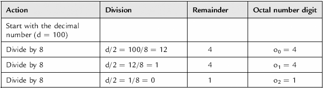
The octal number can be read as: 10010 = (o2o1o0)8 = 1448.
8.7 Hexadecimal-Binary Conversion
The hexadecimal number is a number to the base (or radix) 16, and its magnitude is the sum of the product of the value of each digit in the number (h) and its position (n). This allows the creation of numbers with digits in the set: 0, 1, 2, 3, 4, 5, 6, 7, 8, 9, A, B, C, D, E, F.
The position immediately to the left of the decimal point is zero (0). Moving left from position 0 (in the integer part of the number), the position increments by 1. The value of the digit has a weight of 16n where n is the position number. Moving right from position zero (into the fractional part of the number), the position decrements by 1. The sixteen possible digits are combined to create integers and real numbers. In a decimal equivalent number, the hexadecimal digits A16 to F16 are the numbers 1010 to 1510. Table 8.11 shows the conversion table.
Table 8.11 Hexadecimal-decimal-unsigned four-bit binary conversion
| Hexadecimal number | Decimal number | 4-bit unsigned binary number |
| 0 | 0 | 0000 |
| 1 | 1 | 0001 |
| 2 | 2 | 0010 |
| 3 | 3 | 0011 |
| 4 | 4 | 0100 |
| 5 | 5 | 0101 |
| 6 | 6 | 0110 |
| 7 | 7 | 0111 |
| 8 | 8 | 1000 |
| 9 | 9 | 1001 |
| A | 10 | 1010 |
| B | 11 | 1011 |
| C | 12 | 1100 |
| D | 13 | 1101 |
| E | 14 | 1110 |
| F | 15 | 1111 |
The magnitude of the number (as a decimal number) is given by:

Here, the hexadecimal number is written as hnhn-1hn-2…h0.h−1….h−n (using the decimal equivalent of the hexadecimal number).
Some example hexadecimal numbers are:
For binary numbers, each hexadecimal number represents four bits. Therefore, an 8-bit binary number is represented by two hexadecimal numbers, a 16-bit binary is represented by four hexadecimal numbers, and so on. For example, 816 is 10002 and A816 is 101010002.
![]()
Some example hexadecimal numbers are:
The decimal number equivalent for a hexadecimal number is created by calculating the magnitude of the hexadecimal number, using the decimal equivalent for hexadecimal numbers A to F, as a decimal number:

Converting from decimal to hexadecimal is accomplished in a similar manner to converting from decimal to binary, except now dividing by 16 rather than 2, and using the letters A to F for decimal remainder values of 10 to 15. Consider the number 710. The conversion procedure is shown in Table 8.12.
Table 8.12 Conversion procedure for number 710

The hexadecimal number can be read as: 710 = (h0)16 = 716.
Consider the number 10010. The conversion procedure is shown in Table 8.13.
Table 8.13 Conversion procedure for number 10010

The hexadecimal number can be read as: 10010 = (h1h0)16 = 6416.
Consider the number 25510. The conversion procedure is shown in Table 8.14.
Table 8.14 Conversion procedure for number 25510
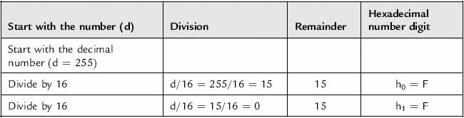
The hexadecimal number can be read as: 25510 = (h1h0)16 = FF16.
Converting from hexadecimal to octal, or vice-versa, is accomplished by converting the number to either a binary or decimal equivalent and from that to the octal to hexadecimal number.
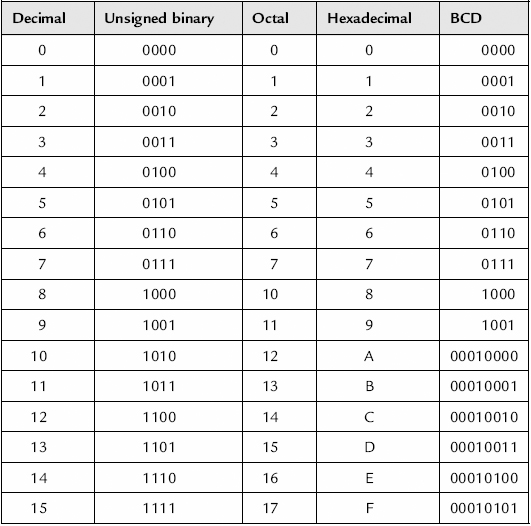
A summary table for the number systems is shown in Table 8.15. Here, unsigned decimal numbers from 010 to 1510 are considered.
Table 8.15 Number systems summary
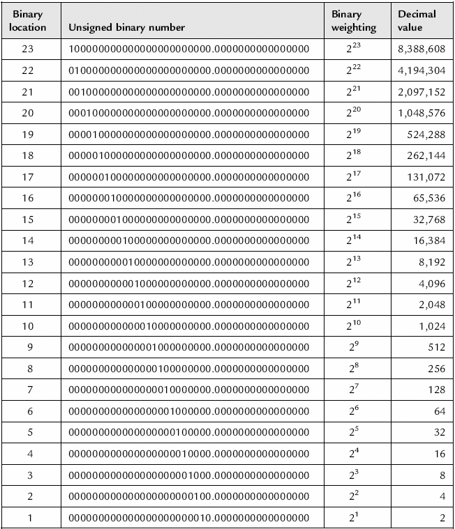
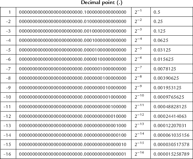
Both binary and decimal numbers can only be integers or real numbers. Table 8.16 shows the binary and decimal numbers for a real number represented by 40 bits in binary, with 24 bits representing the integer part of the number and 16 bits representing the fractional part of the number.
Table 8.16 Decimal-binary conversion table, with the positive position to the left of the decimal point and the negative position to the right of the decimal point and the negative