
9
Propagation of Seismic Waves in Porous Thermoelastic Semi-Infinite Space with Impedance Boundary Conditions
Annu Rani and Dinesh Kumar Madan⋆
Department of Mathematics, Chaudhary Bansi Lal University, Bhiwani, Haryana, India
Abstract
This work investigates the waves propagation in an isotropic saturated porous-thermoelastic medium. The incidence of a seismic wave is considered at the free surface of a thermoelastic semi-infinite space. The surface of semi-infinite space is taken as isothermal. Reflection ratios of waves for the incidence of longitudinal waves are derived for impedance boundary conditions. The graph depicts the effect of porosity on reflection ratios versus incident angle and impedance parameter. Graph plotting is done with the help of the MATLAB programming language. Results are presented for a particular model in this paper.
Keywords: Porous, thermoelastic, reflection, impedance, isothermal
9.1 Introduction
Thermoelasticity is the study of the change in shape and dimension of a solid object when the temperature of the object varies. With the theory of elasticity, Madan et al. [1] and Kumari and Madan [2] explore the propagation of waves. By extending the classical coupled theory of thermoelasticity by introducing relaxation time, Lord and Shulman [3] and Green and Lindsay [4] presented the generalized theory of thermoelasticity. A number of researchers [5–11] have discussed the phenomena of waves reflecting on a free surface. Rani and Madan [12] investigated the effect of initial stress and imperfect interface on waves.
In porous media, the thermo-poroelasticity theory describes the relationship between temperature and stress components. A thermoelastic saturated porous material with solid-fluid pores is a thermally conducting porous solid and these materials are generally found in reservoir rocks of the earth’s crust. The phenomenon of co-existence of thermoelasticity and porosity plays a crucial role in the non-destructive evaluation of composite materials and structures. The propagation of thermoelastic waves in fluidsaturated soil was studied by Haibing [13]. Kumar et al. [14] investigated the Rayleigh waves propagation in thermoelastic semi-infinite space with double porosity under isothermal and insulated boundary conditions in thermoelastic semi-infinite space with double porosity. Wilson et al. [15] discuss the propagation of acoustic waves. In a thermo-poroelastic medium, Wang et al. [16] explored the reflection phenomenon of inhomogeneous elastic waves. The reflection phenomenon of seismic waves at insulated and free surfaces of thermo-poroelastic material was explored by Zorammuana and Singh [17].
Impedance boundary-conditions are defined as a linear combination of unknown parameters and corresponding derivatives that are predictable on the surface. Electromagnetism, acoustics, seismology, science, and technology all benefit from these conditions. The propagation of waves for impedance boundary-conditions was studied by Singh [18], Vinh and Hue [19], Vinh and Xuan [20], and others.
To conclude the wave propagation effects, a quantitative analysis of reflection at the surface of a thermo-poroelastic medium is required. This work examines the waves propagation at the surface of a saturated porous-thermoelastic isothermal medium with an impedance boundary condition. The influence of solid porosity and the Biot parameter for the coupling of fluid and solid phases on the reflection ratios versus impedance parameter and incident angle of a longitudinal wave is studied.
9.2 Basic Equations
The stress-tensors in a non-viscous thermal-porous saturated solid are given by [21]:
where
τij: components of stress,
Pf: pressure of fluid,
β: Biot parameter,
δij: Kronecker delta
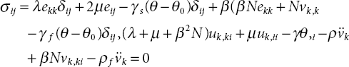
The stress-strain relation is given by [22, 23]
where
λ, μ: lame’s constants,
eij: components of strain,
ϴ: temperature,
γs: coefficient of thermal stress corresponding to solid,
γf: coefficient of thermal stress corresponding to fluid,
N: elastic parameter for bulk-coupling of fluid,
vi = f (Ui − ui),
f: solid porosity,
Ui: component of displacement corresponding to fluid,
ui: component of displacement corresponding to solid,
Also, the strain components are 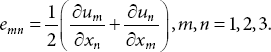
The equation of motion in an isotropic thermal-porous solid saturated with a non-viscous fluid are given by [24]:

where
ρ: porous-aggregate density,
ρf: pore-fluid density,
q: coupling parameter between porous-aggregate solid and pore-fluid,
γ = γs + βγf
9.3 Problem Formulation
Using Equations (9.1)-(9.3) in Equation (9.4), we have:
Using Equations (9.1)-(9.3) in Equation (9.5), we have:
Using Equations (9.1)-(9.3) in Equation (9.6), we have:

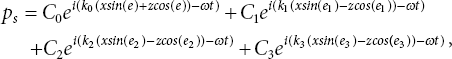
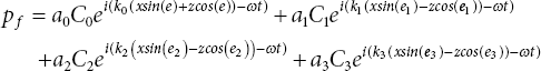
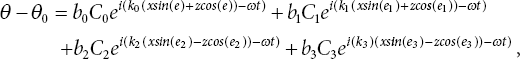
Displacement components in terms of potentials are
Using Equations (9.10) and (9.11) in Equations (9.7)-(9.9), we have:
where ![]() is the Laplace operator.
is the Laplace operator.
The coupling structure of potentials pf, ps with thermal wave can be easily observed from Equations (9.12), (9.14), and (9.16), while the coupling structure of potentials qf and qs can be easily observed from Equations (9.13) and (9.15).
The velocities of waves are [17]


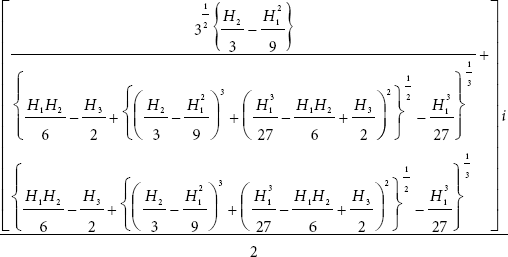
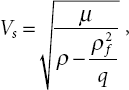
where, ![]()

9.4 Reflection at the Free Surface
Consider an isotropic porous-thermoelastic semi-infinite space, z > 0 (Figure 9.1). If a longitudinal wave is incident with an angle e at the surface, then it will give four reflected waves. Let e1, e2, e3 be angles which reflect coupled longitudinal waves, making them normal, and es be the angle which reflected transverse waves makes normal in medium M.
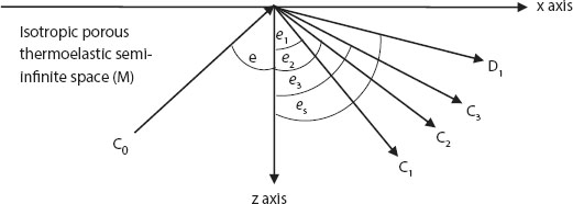
Figure 9.1 Geometry of problem for reflection of waves when longitudinal wave is incident.
where
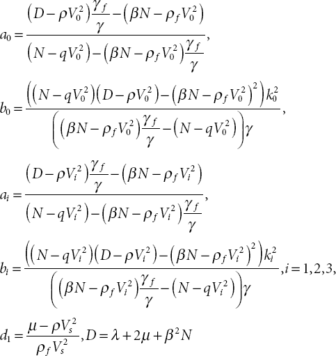
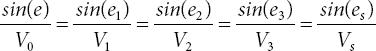
Using Snell’s Law, angles and corresponding wave vectors are associated by:
and in terms of velocities, are given by:
9.4.1 Boundary Conditions
At surface z = 0, impedance boundary conditions are given by [18]:
- σ33 = 0, which gives:
(9.30)

- σ31 + ωZu1 = 0 gives:
(9.31)
 gives:
(9.32)
gives:
(9.32)
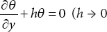 for thermally-insulated surface, h → ∞ for isothermal surface) gives
(9.33)
for thermally-insulated surface, h → ∞ for isothermal surface) gives
(9.33)
where
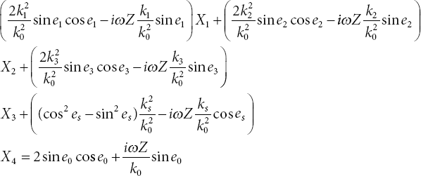
The matrix equation from these equations can be written as
where
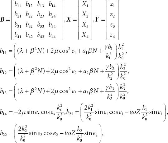

Here, Xi, i = 1, 2, 3, 4 represents reflection ratios in isotropic thermoelastic porous medium.
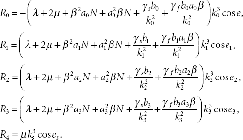
9.4.2 Energy Ratios
The average energy transmission per unit surface area per unit time is given by [25]:
Using Equations (9.22)-(9.28) and (9.37),
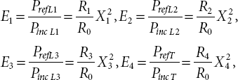
where PrefL1, PrefL2, PrefL3, and PrefT are the average energy of reflected coupled longitudinal waves at e1, e2, e3, and transverse wave at e4, respectively, and
9.5 Numerical Results and Discussion
For the numerical computation of amplitude ratios, we employed the following parameters [24]:

The problem of isothermal surfaces has been studied here. To plot the graphs and execute numerical calculations, the MATLAB programming language is employed. Figure 9.2 explored the impact of porous-parameter f on the reflection ratio of a coupled longitudinal wave at an angle e1 to the incident angle e of the longitudinal wave. It is concluded that as the value of f increases, the reflection ratio of a longitudinal wave decreases for e < 70° and then for e > 70°, attaining the same value for f = 0.03 (circle-line), f = 0.04 (star-line), and f = 0.05 (triangle-line).

Figure 9.2 Reflection ratio X1 of longitudinal wave (at angle e1) against e (incident angle) for β = 0.04, Z = 10, f = 0.03 (circle-line), f = 0.04 (star-line), f = 0.05 (triangle-line).
Variation of the reflection ratios of coupled longitudinal waves at an angle e2, e3 against the incident angle for β = 0.4, Z = 10, f = 0.03 (circle-line), f = 0.04 (star-line), f = 0.05 (triangle-line) is shown in Figures 9.3 and 9.4, respectively. It is concluded that the reflection ratio of a coupled-longitudinal wave against the incident angle attains minimum value at e = 71°, then e > 71° attains the same value for distinct values of f. Qualitatively, the same behavior of the reflection ratios of a longitudinal wave at an angle e2, e3 against the incident angle is observed.
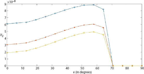
Figure 9.3 Reflection ratio X2 of longitudinal wave (at angle e2) against incident angle e for β = 0.04, Z = 10, f = 0.03 (circle-line), f = 0.04 (star-line), f = 0.05 (triangle-line).

Figure 9.4 Reflection ratio X3 of longitudinal wave (at angle e3) against incident angle e for β = 0.04, Z = 10, f = 0.03 (circle-line), f = 0.04 (star-line), f = 0.05 (triangle-line).
Figure 9.5 explores the variation in amplitude ratio of transverse wave against incident angle e of the longitudinal wave. The reflection ratio of a coupled longitudinal wave attains a maximum value at e = 8° and then decreases gradually. The reflection ratio of a transverse wave behaves qualitatively the same as a coupled longitudinal wave at an angle e2, e3.
Figures 9.6 and 9.7 exhibit variation in the amplitude ratio of a coupled longitudinal wave at angle e1, e2 against impedance parameter Z for f = 0.01, β = 0.1 (represented by circle-line), β = 0.2 (represented by triangle-line), and β = 0.3 (represented by star-line). The magnitude of amplitude ratios of coupled longitudinal wave at angle e1, e2 increases as the value of β increases and attains a maximum value at Z = 50. The amplitude ratios of a coupled longitudinal wave at an angle e3 and transverse wave increases against the impedance parameter Z and attains a maximum value at Z = 50 in Figures 9.8 and 9.9, respectively. It is noticed that the quantitative value of the reflection ratio decreases as the value of β increases.

Figure 9.5 Reflection ratio X4 of transverse wave against incident angle e (in degrees) for β = 0.04, Z = 10, f = 0.03 (circle-line), f = 0.04 (star-line), f = 0.05 (triangle-line).
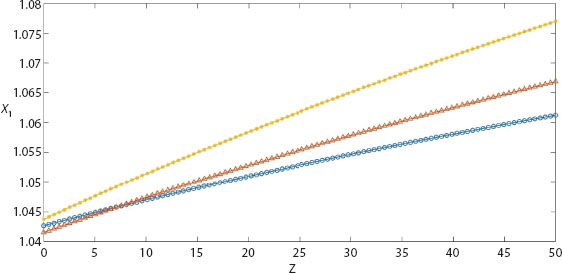
Figure 9.6 Reflection ratio X1 of longitudinal wave at e1 against Z (impedance parameter) for f = 0.01, e = 30°, β = 0.1 (circle-line), β = 0.2 (triangle-line), β = 0.3 (star-line).

Figure 9.7 Reflection ratio X2 of longitudinal wave at e2 against Z (impedance parameter) for f = 0.01, e = 30°, β = 0.1 (circle-line), β = 0.2 (triangle-line), β = 0.3 (star-line).
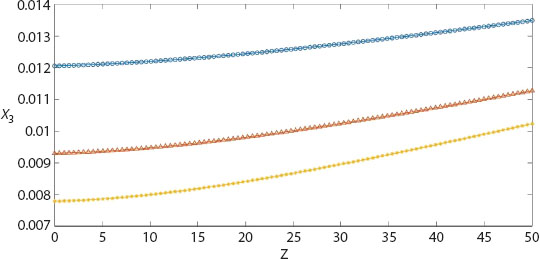
Figure 9.8 Reflection ratio X3 of longitudinal wave at e3 against Z (impedance parameters) for f = 0.01, e = 30°, β = 0.1 (circle-line), β = 0.2 (triangle-line), β = 0.3 (star-line).
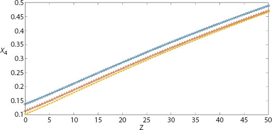
Figure 9.9 Reflection ratio X4 of transverse wave against Z (impedance parameter) for f = 0.01, e = 30°, β = 0.1 (circle-line), β = 0.2 (triangle-line), β = 0.3 (star-line).
Effect of Biot parameter on energy ratios of transverse and longitudinal waves against incident angle of longitudinal wave is shown in Figures 9.10-9.13. It is noticed that the energy ratios of longitudinal and transverse waves achieve a fixed value for incident angle e > 70°. As the value of the Biot parameter grows, the energy ratio of longitudinal waves reflected at an angle e1 decreases, while the energy ratio of longitudinal and transverse waves reflected at angles e1, e2 and e3, respectively, increases against the incident angle of longitudinal waves.
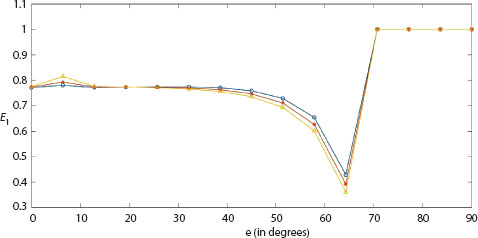
Figure 9.10 Energy ratio E1 of longitudinal wave at e1 against incident angle e for f = 0.05, Z = 10, β = 0.3 (circle-line), β = 0.4 (star-line), β = 0.5 (triangle-line).
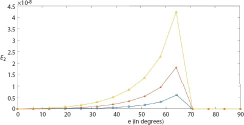
Figure 9.11 Energy ratio E2 of longitudinal wave at e2 against incident angle e for f = 0.05, Z = 10, β = 0.3 (circle-line), β = 0.4 (star-line), β = 0.5 (triangle-line).

Figure 9.12 Energy ratio E3 of longitudinal wave at e3 against incident angle e for f = 0.05, Z = 10, β = 0.3 (circle-line), β = 0.4 (star-line), β = 0.5 (triangle-line).

Figure 9.13 Energy ratio E4 of transverse wave against incident angle e for f = 0.05, Z = 10, β = 0.3 (circle-line), β = 0.4 (star-line), β = 0.5 (triangle-line).
9.6 Conclusion
The effects of porosity and impedance on waves propagating in isotropicporous thermoelastic semi-infinite space is investigated in this work. The following key points are drawn from graphs in this paper:
- As solid porosity increases, the amplitude ratio of the longitudinal wave reflected at an angle e1, drops against the incident angle of longitudinal waves, reaching a minimum value at e = 65° and subsequently, a fixed value for e > 70°
- The reflection ratios of longitudinal waves (at angle e2, e3) and transverse wave falls against incident angle of longitudinal wave, as solid porosity increases, reaching a minimum for e > 70°
- Amplitude ratios of reflected waves in isotropic porous-thermoelastic medium increases with the impedance parameter
- The reflection ratio of the coupled longitudinal waves at angle e1, e2, increases against the impedance parameter with increment of Biot parameter
- The reflection ratio of the longitudinal wave at e3 and transverse wave decreases against the impedance parameter with increment of Biot parameter
- The Biot parameter has less impact on the reflection ratio of the transverse waves
- The energy ratio of the reflected longitudinal waves at an angle e1 drops against the incident angle of longitudinal waves, achieving a minimum value at e = 65° and subsequently a fixed value for e > 70°
- The sum of all energy ratios approaches unity
References
- 1. D.K. Madan, A. Rani and M. Punia, A note on the effect of rigidity and initial stress on the propagation of Rayleigh waves in pre-stressed orthotropic elastic layered medium, Proc. Indian Natl. Sci. Acad., Vol. 87, pp. 487–498, 2021.
- 2. A. Kumari and D.K. Madan, Deformation field due to seismic sources with imperfect Interface, J. Earth Syst. Sci., Vol. 130, pp. 1-19, 2021.
- 3. H. Lord and Y. Shulman, A generalized dynamical theory of thermoelasticity, J. Mech. Phys. Solids, Vol. 15, pp. 299-309, 1967.
- 4. A.E. Green and A. Lindsay, Thermoelasticity, J. Elast., Vol. 2, pp. 1-7, 1972.
- 5. B. Singh, Reflection of P and SV waves from free surface of an elastic solid with generalized thermodiffusion, J. Earth Syst. Sci., Vol. 114, pp. 159-168, 2005.
- 6. A. N. Abd-Alla and A.A.S. Al-Dawy, The reflection phenomenon of SV waves in a generalized thermoelastic medium, Int. J. Math. Sci., Vol. 23, pp. 529-546, 2000.
- 7. J. N. Sharma, V. Kumar and D. Chand, Reflection of generalized thermoelastic waves from the boundary of a half-space, J. Thermal Stresses, Vol. 26, pp. 925-942, 2003.
- 8. S. Abo-dahab, R.A. Mohamed and B. Singh, Rotation and magnetic field effects on P wave reflection from a stress–free surface of elastic half-space with voids under one thermal relaxation time, Journal of Vibration and Control, Vol. 17, pp. 1827-1839, 2010.
- 9. R. Bijarnia and B. Singh, Propagation of plane waves in an anisotropic generalized thermoelastic solid with diffusion, Journal of Engineering Physics and Thermophysics, Vol. 85, pp. 442-448, 2012.
- 10. S. B. Sinha and K. A. Elsibai, Reflection of thermoelastic waves at a solid half-space with two thermal relaxation times, Journal of Thermal Stresses, Vol. 20, pp. 129-146, 1996.
- 11. A.N. Sinha and S.B. Sinha, Reflection of thermoelastic waves at a solid half-space with thermal relaxation, Journal of Physics of the Earth, Vol. 22, pp. 237-244, 1974.
- 12. A. Rani and D.K. Madan, Effect of initial stress and imperfect interface on love waves propagation in prestressed orthotropic layer coated over a pre-stressed orthotropic semi-infinite space, Journal of Rajasthan Academy of Physical Sciences, Vol. 20, pp. 219-228, 2021.
- 13. T. Haibing, L. Ganbin, X. Kanghe, Z. Rongyue and D. Yuebao, Characteristics of wave propagation in the saturated thermoelastic porous medium, Transp Porous Med., Vol. 103, pp. 47-68, 2014.
- 14. R. Kumar, R. Vohra and S. M. Abo-Dahab, Rayleigh waves in thermoelastic medium with double porosity, MOJ Civil engineering. Vol. 4, pp. 143-148, 2018.
- 15. R.K. Wilson and E. S. Aifantis, A double porosity model for acoustic wave propagation in fractured porous rock, Int. J. Engg. Sci., Vol. 22, pp. 1209-1227, 1984.
- 16. E. Wang, J.M. Carcoine, Y. Yuan and J. Ba, Reflection of inhomogeneous plane waves at the surface of a thermo-poroelastic medium, Geophysical Journal International, Vol. 224, pp. 1621-1639, 2021.
- 17. C. Zorammuana and S. S. Singh, Elastic waves in thermoelastic saturated porous Medium, Meccanica, Vol. 51, pp. 593-609, 2016.
- 18. B. Singh, Reflection of plane waves from surface of a generalized thermoviscoelastic porous solid half-space with impedance boundary conditions, Mechanics and Mechanical Engineering, Vol. 22, pp. 1483-1496, 2018.
- 19. P.C. Vinh and T.T. Hue, Rayleigh waves with impedance boundary conditions in anisotropic solids, Wave Motion, Vol. 51, pp. 1082-1092, 2014.
- 20. P.C. Vinh and N.Q. Xuan, Rayleigh waves with impedance boundary condition: Formula for the velocity, existence and uniqueness, Eur. J. Mech. A Solids, Vol. 61, pp. 180-185, 2017.
- 21. M. A. Biot, Mechanics of deformation and acoustic propagation in porousmedia, J Appl Phys, Vol. 33, pp. 1482-1498, 1962.
- 22. J. Bear, S. Sorek, G. Ben-Dor and G. Mazor, Displacement waves in saturated thermoelastic porous media, I. Basic Equations. Fluid Dyn Res, Vol. 9, pp. 155-164, 1992.
- 23. A. Levy, S. Sorek, G. Ben-Dor and J. Bear, Evolution of the balance equations in saturated thermoelastic porous media following abrupt simultaneous changes in pressure and temperature, Trans Porous Media, Vol. 21, pp. 241-268, 1995.
- 24. M.D. Sharma, Wave propagation in thermoelastic saturated porous medium, J Earth Syst Sci., Vol. 117, pp. 951-958, 2008.
- 25. J.D. Achenbach, Wave propagation in elastic solids, North-Holland, Amsterdam, 1973.
Note
- ⋆ Corresponding author: [email protected]