
4.8. Flame Stabilization in High-Velocity Streams
The values of laminar flame speeds for hydrocarbon fuels in air are rarely greater than 45 cm/s. Hydrogen is unique in its flame velocity, which approaches 240 cm/s. If one could attribute a turbulent flame speed to hydrocarbon mixtures, it would be at most a few 100 cm/s. However, in many practical devices, such as ramjet and turbojet combustors in which high volumetric heat release rates are necessary, the flow velocities of the fuel-air mixture are of the order of 50 m/s. Furthermore, for such velocities, the boundary layers are too thin in comparison with the quenching distance for stabilization to occur by the same means as that obtained in Bunsen burners. Thus, some other means for stabilization is necessary. In practice, stabilization is accomplished by causing some of the combustion products to recirculate, thereby continuously igniting the fuel mixture. Of course, continuous ignition could be obtained by inserting small pilot flames. Because pilot flames are an added inconvenience—and because they can blow out themselves—they are generally not used in fast-flowing turbulent streams.

Recirculation of combustion products can be obtained by several means: (1) by inserting solid obstacles in the stream, as in ramjet technology (bluff-body stabilization); (2) by directing part of the flow or one of the flow constituents, usually air, opposed or normal to the main stream, as in gas turbine combustion chambers (aerodynamic stabilization); or (3) by using a step in the wall enclosure (step stabilization), as in the so-called “dump” combustors. These modes of stabilization are depicted in Figure 4.52. Complete reviews of flame stabilization of premixed turbulent gases appear in Refs [69,70].
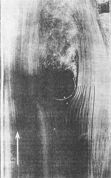
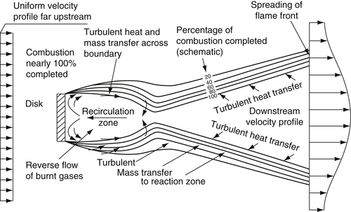
Photographs of ramjet-type burners, which use rods as bluff obstacles, show that the regions behind the rods recirculate part of the flow that reacts to form hot combustion products; in fact, the wake region of the rod acts as a pilot flame. Nicholson and Fields [71] graphically showed this effect by placing small aluminum particles in the flow (Figure 4.53). The wake pilot condition initiates flame spread. The flame spread process for a fully developed turbulent wake was depicted [69], as shown in Figure 4.54. The theory of flame spread in a uniform laminar flow downstream from a laminar mixing zone was fully developed [12,69] and revealed that the angle of flame spread is sin−1(SL/U), where U is the main stream flow velocity. For a turbulent flame one approximates the spread angle by replacing SL by an appropriate turbulent flame speed ST. The limitations in defining ST in this regard were described in Section 4.6.
The types of obstacles used in stabilization of flames in high-speed flows could be rods, vee gutters, toroids, disks, strips, etc. But in choosing the bluff-body stabilizer, the designer must consider not only the maximum blowoff velocity the obstacle will permit for a given flow, but also pressure drop, cost, ease of manufacture, etc.
Since the combustion chamber should be of minimum length, it is rare that a single rod, toroid, etc., is used. In Figure 4.55, a schematic of flame spreading from multiple flame holders is given. One can readily see that multiple units can appreciably shorten the length of the combustion chamber. However, flame holders cause a stagnation pressure loss across the burner, and this pressure loss must be added to the large pressure drop as a result of burning. Thus, there is an optimum between the number of flame holders and pressure drop. It is sometimes difficult to use aerodynamic stabilization when large chambers are involved because the flow creating the recirculation would have to penetrate too far across the main stream. Bluff-body stabilization is not used in gas turbine systems because of the required combustor shape and the short lengths. In gas turbines a high weight penalty is paid for even the slightest increase in length. Because of reduced pressure losses, step stabilization has at times commanded attention. A wall heating problem associated with this technique would appear solvable by some transpiration cooling. Adding a tangential velocity component to the flow, swirl, is often used to induce an unfavorable pressure gradient along the flow direction for flow reversal and recirculation.
In either case, bluff-body or aerodynamic, blowout is the primary concern. In ramjets, the smallest frontal dimension for the highest flow velocity to be used is desirable; in turbojets, it is the smallest volume of the primary recirculation zone that is of concern; and in dump combustors, it is the least severe step.

There were many early experimental investigations of bluff-body stabilization. Most of this work [69] used premixed gaseous fuel-air systems and typically plotted the blowoff velocity as a function of the air–fuel ratio for various stabilized sizes, as shown in Figure 4.56. Early attempts to correlate the data appeared to indicate that the dimensional dependence of blowoff velocity was different for different bluff-body shapes. Later, it was shown that the Reynolds number range was different for different experiments and that a simple independent dimensional dependence did not exist. Furthermore, the state of turbulence, the temperature of the stabilizer, incoming mixture temperature, etc., also had secondary effects. All these facts suggest that fluid mechanics plays a significant role in the process.

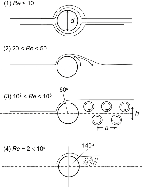
Considering that fluid mechanics has an important role, it is worth examining the cold flow field behind a bluff body (rod) in the region called the wake. Figure 4.57 depicts the various stages in the development of the wake as the Reynolds number of the flow is increased. In region (1), there is only a slight slowing behind the rod and a slight region of separation. In region (2), a pair of vortices, fixed in the wake, start to form, and the stagnation points are as indicated. As the Reynolds number increases, the eddy (vortex) size increases and the downstream stagnation point moves farther away from the rod. In region (3), the eddies become unstable, shed alternately, as shown in the figure, and (h/a) ∼ 0.3. As the velocity u increases, the frequency N of shedding increases; N ∼ 0.3(u/d). The stagnation (separation) point moves past 90° to about 80°, and the boundary layer upstream of the separation point remains laminar. In region (4), there is a complete turbulent wake behind the body. A further increase in the flow velocity (Re ∼2 × 10⁵) results in the laminar boundary layer transitioning to a turbulent boundary layer prior to separation, delaying the separation point to about 140° and reducing the size of the turbulent wake. The turbulent wake behind the body is eventually destroyed downstream by jet mixing.
The flow fields described in Figure 4.57 are specific in that they apply to cold flow over a cylindrical body. When spheres are immersed in a flow, region (3) does not exist. More striking, however, is the fact that when combustion exists over this Reynolds number range of practical interest, the shedding eddies disappear and a well-defined, steady vortex is established. The reason for this change in flow pattern between cold flow and a combustion situation is believed to be due to the increase in kinematic viscosity caused by the rise in temperature. Thus, the Reynolds number affecting the wake is drastically reduced, as discussed in the section of premixed turbulent flow. Then, it would be expected that in region (2) the Reynolds number range would be 10 < Re < 105. Flame holding studies by Zukoski and Marble [73,74] showed that the ratio of the length of the wake (recirculation zone) to the diameter of the cylindrical flame holder was independent of the approach flow Reynolds number above a critical value of about 104. These Reynolds numbers are based on the critical dimension of the bluff body: that is, the diameter of the cylinder. Thus, one may assume that for an approach flow Reynolds number greater than 104, a fully developed turbulent wake would exist during combustion.
Experiments [69] have shown that any original ignition source located upstream, near or at the flame holder, appears to establish a steady ignition position from which a flame spreads from the wake region immediately behind the stabilizer. This ignition position is created by the recirculation zone that contains hot combustion products near the adiabatic flame temperature [65]. The hot combustion products cause ignition by transferring heat across the mixing layer between the free-stream gases and the recirculation wake. Based on these physical concepts, two early theories were developed that correlated the existing data well. One was proposed by Spalding [75] and the other by Zukoski and Marble [73,74]. Another early theory of flame stabilization was proposed by Longwell et al. [76], who considered the wake behind the bluff body to be a stirred reactor zone.
Considering the wake of a flame holder as a stirred reactor may be inconsistent with experimental data. It has been shown [69] that as blowoff is approached, the temperature of the recirculating gases remains essentially constant; furthermore, their composition is practically all products. Both of these observations are contrary to what is expected from stirred reactor theory. Conceivably, the primary zone of a gas turbine combustor might approach a state that could be considered completely stirred. Nevertheless, as will be shown, all three theories give essentially the same correlation.
Zukoski and Marble [73,74] held that the wake of a flame holder establishes a critical ignition time. Their experiments, as indicated earlier, established that the length of the recirculating zone was determined by the characteristic dimension of the stabilizer. At the blowoff condition, they assumed that the free-stream combustible mixture flowing past the stabilizer had a contact time equal to the ignition time associated with the mixture; that is, τw = τi, where τw is the flow contact time with the wake and τi is the ignition time. Since the flow contact time is given by
![]()
where L is the length of the recirculating wake, and UBO is the velocity at blowoff, they essentially postulated that blowoff occurs when the Damkohler number has the critical value of one; that is,
![]()
The length of the wake is proportional to the characteristic dimension of the stabilizer, the diameter d in the case of a rod, so that
![]()
Thus it must follow that
![]()
For second-order reactions, the ignition time is inversely proportional to the pressure. Writing the relation between pressure and time by referencing them to a standard pressure P0 and time τ0, one has
![]()
where P is the actual pressure in the system of concern.
The ignition time is a function of the combustion (recirculating) zone temperature, which, in turn, is a function of the air–fuel ratio (A/F). Thus,
![]()
Spalding [75] considered the wake region as one of steady-state heat transfer with chemical reaction. The energy equation with chemical reaction was developed and nondimensionalized. The solution for the temperature profile along the outer edge of the wake zone, which essentially heats the free stream through a mixing layer, was found to be a function of two nondimensional parameters that are functions of each other. Extinction or blowout was considered to exist when these dimensionless groups were not of the same order. Thus, the functional extinction condition could be written as
![]()
where d is, again, the critical dimension, α is the thermal diffusivity, Z′ is the pre-exponential in the Arrhenius rate constant, and n is the overall reaction order.
From laminar flame theory, the relationship
![]()
was obtained, so that the preceding expression could be modified by the relation
![]()
Since the final correlations have been written in terms of the air–fuel ratio, which also specifies the temperature, the temperature dependences were omitted. Thus, a new proportionality could be written as
![]()
![]()
and the original functional relation would then be
![]()
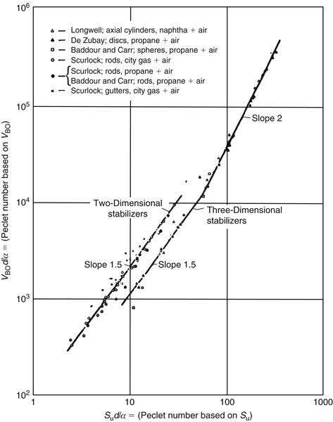
Both correlating parameters are in the form of Peclet numbers, and the air–fuel ratio dependence is in SL. Figure 4.58 shows the excellent correlation of data by the above expression developed from the Spalding analysis. Indeed, the power dependence of d with respect to blowoff velocity can be developed from the slopes of the lines in Figure 4.58. Notice that the slope is 2 for values (UBOd/α) > 104, which was found experimentally to be the range in which a fully developed turbulent wake exists. The correlation in this region should be compared with the correlation developed from the work of Zukoski and Marble.
Stirred reactor theory was initially applied to stabilization in gas turbine combustor cans in which the primary zone was treated as a completely stirred region. This theory has sometimes been extended to bluff-body stabilization, even though aspects of the theory appear inconsistent with experimental measurements made in the wake of a flame holder. Nevertheless, it would appear that stirred reactor theory gives the same functional dependence as the other correlations developed. In the previous section, it was found from stirred reactor considerations that
![]()
for second-order reactions. If  is considered to be the mass entering the wake and V its volume, then the following proportionalities can be written:
![]()
![]()
which is the same result as that obtained by Zukoski and Marble. Indeed, in the turbulent regime, Spalding’s development also gives the same form, since in this regime the correlation can be written as the equality
![]()
Then it follows that
![]()
Thus, for a second-order reaction,
![]()
From these correlations it would be natural to expect that the maximum blowoff velocity as a function of air–fuel ratio would occur at the stoichiometric mixture ratio. For premixed gaseous fuel–air systems, the maxima occur at this mixture ratio, as shown in Figure 4.56. However, in real systems, liquid fuels are injected upstream of the bluff-body flame holder to allow for mixing. Results [63] for such liquid injection systems show that the maximum blowoff velocity is obtained on the fuel-lean side of stoichiometric. This trend is readily explained by the fact that liquid droplets impinge on the stabilizer and enrich the wake. Thus, a stoichiometric wake undoubtedly occurs for a lean upstream liquid-fuel injection system. That the wake can be modified to alter blowoff characteristics was proved experimentally by Fetting et al. [77]. The trends of these experiments can be explained by the correlations developed in this section.
When designed to have sharp leading edges, recesses in combustor walls cause flow separation, as shown in Figure 4.52(c). During combustion, the separated regions establish recirculation zones of hot combustion products much like the wake of bluff-body stabilizers. Studies [78] of turbulent propane–air mixtures stabilized by wall recesses in a rectangular duct showed stability limits significantly wider than that of a gutter bluff-body flame holder and lower pressure drops. The observed blowoff limits for a variety of symmetrically located wall recesses showed [69] substantially the same results, provided: (1) the recess was of sufficient depth to support an adequate amount of recirculating gas, (2) the slope of the recess at the upstream end was sharp enough to produce separation, and (3) the geometric construction of the recess lip was such that flow oscillations were not induced.
The criterion for blowoff from recesses is essentially the same as that developed for bluff bodies, and L is generally taken to be proportional to the height of the recess [78]. The length of the recess essentially serves the same function as the length of the bluff-body recirculation zone unless the length is large enough for flow attachment to occur within the recess, in which case the recirculation length depends on the depth of the recess [12]. This latter condition applies to the so-called dump combustor, in which a duct with a small cross-sectional area exhausts coaxially with a right-angle step into a duct with a larger cross-section. The recirculation zone forms at the step.
Recess stabilization appears to have two major disadvantages. The first is the result of the large increase in heat transfer in the step area, and the second of flame spread angles smaller than those obtained with bluff bodies. Smaller flame spread angles demand longer combustion chambers.
Establishing a criterion for blowoff during opposed jet stabilization is difficult owing to the sensitivity of the recirculation region formed to its stoichiometry. This stoichiometry is well defined only if the main stream and opposed jet compositions are the same. Since the combustor pressure drop is of the same order as that found with bluff bodies [79], the utility of this means of stabilization is questionable.
..................Content has been hidden....................
You can't read the all page of ebook, please click here login for view all page.