
Chapter 9. Introduction to Reliefs
The learning objectives for this chapter are to:
Explain the importance of pressure protection.
Describe the relief design procedure.
Define terms related to relief design.
Specify relief design code requirements.
Identify relief types and characteristics.
Discuss relief installation practices.
Describe relief effluent handling systems.
Chemical processes operate over a wide range of pressures. These pressures are required to move materials through the process and to ensure that the unit operations work properly. The pressures utilized range from vacuum to atmospheric to hundreds or thousands of bars.
All equipment in a process cannot be designed to withstand the highest and lowest pressures—this is not practical and would be very costly. Thus, equipment must be designed to withstand the pressure requirements at that specific point in the process. This practice creates hazards, however: Process upsets, operator errors, design mistakes, and other problems can expose equipment to pressures that they were not designed to handle.
High or low pressure in process equipment, when it exceeds the equipment’s design limits, can cause damage or failure of the equipment and even personnel injury. It may also result in a release of toxic or flammable materials and, in some cases, an explosive rupture. Many significant accidents have been caused by high or low pressures in process equipment.
Chemical plants contain a very broad range of different types of equipment—for example, pressure vessels, low-pressure storage tanks, piping, and mechanical machinery (e.g., pumps, compressors). All of this equipment must be designed for the required pressure, though different rules apply to different equipment.
Inherent, passive, active, and procedural approaches (described in Table 1-21), coupled with preventive and mitigative safeguards (listed in Table 1-17), must be fully applied to prevent incidents caused by pressure. An additional safeguard is provided by the installation of relief systems to discharge liquids and/or gases before damaging pressures develop. The relief system is composed of a relief device and the associated downstream equipment to safely handle the discharged effluent material.
Pressure relief devices (PRDs), also called pressure relief valves (PRVs), are considered preventive safeguards because they protect process equipment from the damaging effects of pressure. However, once a relief device opens, there will still be impacts associated with loss of material, cleanout, downtime, possible effects on people and/or the environment, and other possible costs such as an incident investigation. The effluent handling system downstream of the relief device, by comparison, is considered a mitigative safeguard because it contains the discharged material. Relief device activation is considered a leading indicator of process safety and must be managed appropriately.
It is commonly believed that the main purpose of the relief device is to discharge mass from the process. In reality, the high pressure in the process is caused by energy, not mass, so the relief device reduces the pressure by discharging mass with energy content.
A typical chemical plant may contain hundreds or even thousands of relief systems. Each relief system must be properly designed, fully documented, and appropriately maintained. This requires a huge effort, but is necessary to ensure the safety of the process.
In the United States, a pressure vessel is defined as any vessel designed for a pressure rating of 15 psig (1.03 bar gauge) or more and is legally required to have a relief device. Vessels and equipment that are designed for lower pressures also need pressure and vacuum protection.
Storage vessels are typically designed to withstand no more than a few inches of water gauge pressure or vacuum, and are normally equipped with bimodal conservation vents that are activated by pressure or vacuum. Relief devices for these vessels are designed only for vapor relief—not for liquid discharge. Instrumentation and/or procedural safeguards are used to mitigate the liquid overfilling scenario. Storage vessel reliefs are not considered here.
This chapter presents qualitative information on relief devices in liquid or gas service. Chapter 10 provides quantitative information on sizing relief devices. In the case of gas or dust combustion, the reliefs are called deflagration vents; they are also described in Chapter 10.
9-1 Relief Concepts
Typical pressure versus time curves for a runaway reaction in a pressure vessel reactor are shown in Figure 9-1. Suppose an exothermic reaction occurs in a pressure vessel, loss of cooling occurs, and the temperature begins increasing rapidly. The pressure within the reactor increases due to the increased temperature, resulting in increased vapor pressure of the liquid reactants.

Curve D on Figure 9-1 shows the pressure–time plot for a closed reactor vessel without a relief device that is capable of fully withstanding the maximum pressure during the runaway reaction. The temperature and pressure will rise rapidly until all the reactants are consumed and the reaction terminates. The temperature and pressure will reach a maximum value and then slowly decrease due to heat losses through the reactor vessel wall to the surroundings.
If a relief device is present on the reactor, that device will open at the set pressure shown in Figure 9-1. The behavior of the pressure in the reactor after the relief device opens is highly dependent on the nature of the fluid discharged through the relief device.
Curve A on Figure 9-1 shows a typical pressure versus time plot for an all-vapor discharge. After the relief device opens, the pressure continues to rise, but the pressure soon drops because only a small amount of vapor discharge is required to decrease the pressure. Repeated opening and closing of the relief device is likely.
Curve B shows a typical pressure versus time plot for an all-liquid discharge through the relief device. After the relief device opens, the pressure continues to increase, but eventually adequate liquid is discharged to decrease the pressure.
Curve C shows a typical pressure versus time plot for two-phase flow or froth. Froth is composed of small gas bubbles that are uniformly entrained in the liquid; it is similar to the froth produced by opening a soda can after shaking it. A substantial pressure increase after relief opening is expected with froth for several reasons. First, the discharge velocity of the froth is lower than that of liquid due to increased friction from the froth flow. Second, the mass discharge rate is lower because of the lower froth density due to the presence of the froth bubbles. Eventually, adequate froth is discharged to decrease the pressure. Two-phase relief flow is expected with liquid exothermic runaway reactions.
9-2 Definitions1
1API RP 520, Sizing, Selection and Installation of Pressure-relieving Devices, Part I: Sizing and Selection, 9th ed. (Washington, DC: American Petroleum Institute, 2014).
The following definitions are applicable to relief systems:
Set pressure: The inlet gauge pressure at which the pressure relief device begins to open under service conditions.
Maximum allowable working pressure (MAWP): The maximum gauge pressure permissible at the top of a vessel for a designated temperature; sometimes called the design pressure. As the vessel temperature increases, the MAWP decreases because the vessel wall metal strength decreases. Likewise, as the operating temperature decreases, the MAWP decreases because of metal embrittlement at lower temperatures. Vessel failure typically occurs at 4 to 5 times the MAWP, although vessel deformation may occur at as low as twice the MAWP.
Maximum allowable working temperature (MAWT): The temperature associated with the MAWP for a pressure vessel.
Minimum design metal temperature (MDMT): The minimum operating temperature for a pressure vessel. Below this temperature, the metal loses strength due to metal embrittlement.
Operating pressure: The gauge pressure in a pressure vessel during normal operations. This is usually no more than 90% of the MAWP for the vessel.
Accumulation: The pressure increase in a vessel over the MAWP during the relief process. It is expressed as a percentage of the MAWP (see Figure 9-2).

Overpressure: The pressure increase in a vessel over the set pressure during the relieving process. It is expressed as a percentage of the set pressure. Overpressure is equivalent to the accumulation when the set pressure is at the MAWP. The overpressure is usually a design specification for a relief device and depends on the pressure capability of the protected equipment (see Figure 9-2).
Backpressure: The pressure at the outlet of the relief device during the relief process resulting from pressure in the downstream discharge system. Backpressure is composed of two components. The first component is the superimposed backpressure due to pressure in the discharge header before the relief device opens. The superimposed backpressure can be constant or variable. The second component is the built-up backpressure due to the pressure in the discharge header as a result of frictional fluid flow losses in the downstream piping after the valve opens and fluid is discharging. The total backpressure is the sum of the superimposed and built-up backpressures. Relief device operation is affected by backpressure and must be considered in the relief design.
Blowdown: The pressure difference between the relief set pressure and the relief reseating pressure expressed as a percentage of the set pressure or in pressure units (discussed in Section 9-4).
Maximum allowable accumulation pressure: The sum of the MAWP and the allowable accumulation.
Maximum allowable relief pressure: The maximum pressure allowed by code during the relieving process.
Relieving pressure: The total of the set pressure plus overpressure.
Relief scenario: A description of the events and circumstances that lead to a high or low pressure in process equipment.
Design basis: The collected design information related to the relief device. This includes the scenario, physical properties, reaction kinetics, equipment configuration, and all other design information.
Figure 9-2 shows how the overpressure and accumulation are related. During the relieving process, the relief device begins to open at the set pressure, but the pressure continues to increase beyond the set pressure. Eventually, the pressure reaches a peak at the overpressure and begins to decrease. The overpressure is an important design specification for the relief device: It would be impractical to design a relief device to open and maintain the pressure at the set pressure. Note that the overpressure is defined as a percentage of the set pressure. The accumulation is defined as a percentage of the MAWP.
9-3 Code Requirements
Pressure protection is influenced by a broad range of codes and standards, some of which are listed in Table 9-1. Most of these codes and standards came about in the late 1800s and early 1900s primarily due to steam boiler explosions, which were very common at that time and resulted in many fatalities.
Table 9-1 Codes and Standards That Apply to Pressure Protection
ASME Boiler and Pressure Vessel Code (New York, NY: American Society of Mechanical Engineers, 2017). API RP 520, Sizing, Selection and Installation of Pressure-Relieving Devices, Part I: Sizing and Selection, 9th ed. (Washington, DC: American Petroleum Institute, 2014). This applies for vessels rated for 15 psig (1.034 barg) to 3000 psig (206.8 bar). API RP 520, Sizing, Selection and Installation of Pressure-Relieving Devices, Part II: Installation, 6th ed. (Washington, DC: American Petroleum Institute, 2015). API RP 521, Pressure-Relieving and Depressurizing Systems, 6th ed. (Washington, DC: American Petroleum Institute, 2014). API RP 526, Flanged Steel Pressure-Relieving Valves, 7th ed. (Washington, DC: American Petroleum Institute, 2017). API Std 620, Design and Construction of Large, Welded, Low Pressure Storage Tanks, 12th ed. (Washington, DC: American Petroleum Institute, 2013). This applies to vessels rated from 2.5 psig (0.172 barg) to 15 psig (1.034 barg). API Std 650, Welded Steel Tanks for Oil Storage, 12th ed. (Washington, DC: American Petroleum Institute, 2013). This applies to vessels rated from atmospheric to 2.5 psig (0.172 barg). API Std 2000, Venting Atmospheric and Low-Pressure Storage Tanks, 7th ed. (Washington, DC: American Petroleum Institute, 2014). |
Notes: RP: Recommended Practice; Std: Standard.
Figure 9-3 shows the pressure requirements for relief devices as defined by the American Petroleum Institute (API) Recommended Practice (RP) 521. The vertical scale on Figure 9-3 is defined with respect to the MAWP at 100%.

The usual maximum operating pressure is 90% of the MAWP shown at the bottom of the scale on Figure 9-3. By code, the MAWP must never be exceeded during normal operation, even momentarily.
Also at the bottom of the scale on Figure 9-3 is the leak test pressure at no more than 90% of the MAWP. Leak tests are usually done using gas.
Pressure tests on vessels are done at 150% of the MAWP, as shown in Figure 9-3, and are usually performed using water—not gas. If the vessel fails in a test using gas, an explosion could result as the gas expands. In contrast, water will not expand if the vessel fails during the test. During the pressure test, the vessel will expand due to the pressure. If this expansion is below a certain specified value, the vessel passes the test. An additional requirement for liquid pressure testing is that the vessel must have the mechanical strength to hold the weight of the liquid during this test—not all pressure vessels meet this requirement.
For a single relief device, Figure 9-3 shows that the maximum set pressure is 100%, the maximum overpressure is 110%, and the maximum relieving pressure during relief operation is 116%, all with respect to the MAWP.
Figure 9-3 also shows the code requirements for single and supplemental relief devices installed in a process. For some types of process equipment, such as a chemical reactor, supplemental relief devices are used when there are widely differing relief scenarios. Each relief device is designed for a specific relief scenario. A smaller primary relief device with a lower set pressure and lower capacity would be used for a relief scenario of lesser magnitude, such as a nominal pressure excursion during normal operation. A larger supplemental relief device with a higher set pressure and larger capacity would be used for a much larger relief scenario, such as a runaway reaction or vessel fire exposure. For multiple relief devices, the maximum set pressure is 105%, the maximum overpressure is 116%, and the maximum relieving pressure is 121%, all with respect to the MAWP.
For fire exposures, the maximum set pressure is 105% of the MAWP and the maximum relieving pressure is 121% of the MAWP.
The selection of a set pressure is a very important part of the relief device design. Although you might be inclined to specify a set pressure equal to the maximums shown in Figure 9-3, a more prudent approach is to specify a set pressure based on the normal operating pressure of the process. Suppose a process operates at 2 bar and the MAWP of the vessel is 3 bar. If the maximum pressure excursion during normal operation of the process is 2.2 bar, then establishing the set pressure as 2.5 bar, rather than as the MAWP of 3 bar, would provide an additional safety margin.
The blowdown is defined with respect to the reseat pressure and may or may not be the same as the set pressure, depending on the type of relief device. Blowdown is discussed in Section 9-5.
Figure 9-3 contains several important maximum pressures that cannot be exceeded:
The maximum normal operating pressure can never exceed the MAWP, even momentarily. However, the actual pressure during the relieving process may exceed the MAWP.
For a single relief, the maximum set pressure is the MAWP.
During the relieving process. the overpressure cannot exceed the MAWP by more than the following percentages:
110% for vessels equipped with a single pressure relief device
116% for vessels equipped with supplemental pressure relief devices
121% for fire exposures
For supplemental relief devices, the maximum set pressure is 105% of the MAWP.
For supplemental relief devices, the maximum set pressure for fire exposure is 110% of the MAWP.
Vessels must also be protected from pressure due to vacuum. It cannot be assumed that vessels rated for pressure are rated for vacuum, since these pressure forces occur in opposite directions. The consequences of vessel failures due to vacuum, however, are generally less severe than failures caused by internal pressure.
The requirements for vacuum protection differ from those for pressure protection. In particular, there are no prescriptive requirements for vacuum protection. Standard practice is to design the vessel for the worst-case vacuum scenario. However, if a vessel can be exposed to vacuum, then it should be designed for full vacuum, if possible. If the vessel cannot be designed for full vacuum, the risks must be carefully evaluated and the necessary safeguards must be implemented.
If the relief is installed to handle multiple scenarios, it might work appropriately for the primary design scenario, but the performance might not be satisfactory for other scenarios. An example is a relief designed primarily for vapor service that must also handle a liquid scenario. The liquid case might present some performance issues.
9-4 Relief System Design
Table 9-2 describes the steps required for a typical relief system design. Most relief system designs involve compromises.
Table 9-2 Typical Steps in Relief System Design
Identify: |
Obtain:
|
Determine:
|
Document:
|
Review:
|
Inspect:
|
Manage:
|
Source: Adapted from Center for Chemical Process Safety. Guidelines for Pressure Relief and Effluent Handling Systems, 2nd ed. (Hoboken, NJ: John Wiley & Sons, 2017).
Step 1 identifies the equipment that must be protected. Table 9-3 lists process equipment that typically requires pressure protection. The methods for pressure protection will differ depending on the equipment being protected.
Table 9-3 Typical Process Equipment Requiring Pressure Protection
|
An up-to-date Piping and Instrument Diagram (P&ID; see Appendix F) and specifications on all process equipment, piping, and instrumentation are required for this step. The boundaries of a protected system are typically determined based on the location of isolation or block valves.
Vessels require pressure protection even if there are no identified causes for overpressure. The lack of a scenario simply means that there is no sizing basis for the relief device, but a relief device is still required for regulatory compliance.
Most piping systems do not need pressure protection because piping systems are generally designed for a higher pressure than the connected vessels. The exceptions are as follows:
Piping segments that are periodically isolated while full of liquid that can be heated by ambient conditions or sun exposure.
Heat-traced liquid-filled lines.
Long lines (i.e., more than 300 ft [91.4 m]) that are not in continuous service. These lines generally need protection from liquid thermal expansion.
Loading and transfer lines and other lines that extend beyond the property line or battery limits.
Lines with a history of overpressure, as indicated by gasket blowout.
A low-pressure piping system that is connected to a high-pressure system. An example is a low-pressure steam header that is connected to a high-pressure steam system through a pressure regulator; a failure of the pressure regulator will expose the low-pressure piping to high pressure.
Pumps can overpressure downstream equipment. In particular, positive displacement pumps require reliefs, whereas centrifugal pumps may or may not require a relief. Many pumps include internal reliefs provided by the manufacturer—but many companies prefer to provide their own external reliefs because the internal reliefs are difficult to maintain or replace. Relief devices on pumps typically discharge to the inlet side of the pump, but the pump fluid may become heated due to continuous recirculation of the liquid.
The coolant side of heat exchangers may or may not need a relief; it depends on the service. If maintenance valves are present on the coolant tubes and the valves are closed, then hot vapor or liquid on the hot side of the exchanger will expand the liquid, potentially causing tube rupture.
Step 2 identifies all the scenarios for each piece of equipment that are a potential cause for high and low pressure. Usually, many scenarios are associated with each equipment piece. This procedure requires the review of every unit operation in the process and every process operating step. Table 9-4 shows common sources for pressure and vacuum. Scenarios are typically bound by the location of block valves. Also consider normal and other modes of operation, such as startup and shutdown. Relief scenarios with the potential for high and low pressures must be identified.
Table 9-4 Some Common Sources of Pressure and Vacuum
Heat Related Fire, usually external to the process Out-of-control heaters and coolers Loss of cooling or heating Ambient temperature changes Runaway chemical reactions |
Equipment and Systems Any high- or low-pressure source in the process Any equipment malfunction Pumps Compressors Vaporizers Condensers Vent manifold interconnections Utility headers (e.g., steam, air, water, nitrogen) Valves, either open or closed Pressure regulators Chemical reactors |
Physical Changes Boiling Condensing Freezing |
Gas absorption (e.g., HCl in water) Thermal expansion Vapor condensation |
Operations Operator or operations error Mischarge or contamination of reactants, catalysts, or monomers Improper maintenance Design error |
The codes and standards leave it up to the user to determine the relief sizing scenarios for each relief device. It is the user’s responsibility to determine which relief scenarios are credible. This step in the relief system design is extremely important because the identification of the relief scenarios has a more significant effect on the design than the actual relief sizing. This procedure cannot be standardized and requires judgment and experience.
The following questions are typically asked during this step:
What happens with loss of cooling, heating, or agitation?
What happens if the process is contaminated or has a mischarge of a catalyst or monomer?
What happens if the operator makes an error?
What is the consequence of closing block valves on vessels or in lines that are filled with liquids?
Many other scenarios are also possible.
After all the scenarios are identified, the next step is to determine the credible scenarios. A credible scenario is a single failure scenario—multiple independent failures are typically not considered. A more detailed risk assessment procedure might be required here (see Chapters 11 and 12).
Step 3 identifies the worst-case scenario that requires the largest relief area. The largest area might not correspond to the maximum mass flow rate. The process conditions that correspond to these scenarios must be clearly established.
Step 4 obtains physical, thermal, reactive, and other properties of the material being discharged through the relief. A literature search of company and external references is typically done—but all values obtained must be certified. Laboratory testing may be required to determine the properties of some materials, particularly reactive properties.
Step 5 determines the required relief capacity for the worst-case scenario identified in Step 3.
Step 6 determines the characteristics and behavior of the vessel contents and discharge fluid during the scenario. This could include the following cases:
Reactive versus nonreactive systems.
Equipment type and configuration: A reactor vessel will vent differently than a heat exchanger.
Potential foaminess of discharged material resulting in liquid venting with vapor.
Single-phase versus two-phase fluid in the vent system. Two-phase flow is likely with exothermic reactions and possible with fire exposure involving liquids that are inherently foamy, contain surfactants, or have a high liquid viscosity.
The evaporative cooling effects due to condensable vapor.
Location of the relief vent opening with respect to liquid level or two-phase interface.
Other possible important cases.
Step 7 determines the set pressure, allowable overpressure and other specifications depending on the equipment type and configuration. See Section 9-3.
Step 8 determines the appropriate type of relief device. There are many types to choose from, as described in Section 9-5. Specific types of relief devices are chosen based on the process conditions, the type and physical properties of the relieved fluid, the requirements of the downstream effluent handling system, cost, and relief performance characteristics.
Step 9 determines the size of the relief using information from all the previous steps. The sizing calculations depend on the relief type and the characteristics of the discharge relief fluid. Chapter 10 provides details on these calculations.
Step 10 determines how to handle the effluent discharged from the relief system. Clearly, toxic, flammable, and reactive chemicals cannot be discharged into the work area or into the environment where human harm and environmental impact could occur. An appropriate relief effluent handling process must be selected, and the design capacities of the associated equipment must be established. This topic is discussed further in Section 9-7.
Step 11 determines the mass and reaction force loading requirements on the downstream effluent handling system to ensure the mechanical integrity of the relief system. When the relief device opens, large quantities of mass are ejected at a very high velocity. This creates a very high reaction or thrust force on the system. The weight of the discharged mass contained in the relief system piping and vessels can be significant.
Step 12 documents all of the information up to this point related to the relief system.
Step 13 is a comprehensive review of the entire relief system design. At this point, the relief system exists only on paper; this is the last step before its construction. It is important to rely on independent reviewers with equal or greater relief design experience to evaluate the proposed design.
Step 14 involves inspection of the relief system as it is being constructed and a final comprehensive inspection after construction is completed. Changes during construction must be carefully reviewed and documented.
Step 15 develops and manages appropriate testing and maintenance procedures for the entire relief system. A relief device has no safety integrity unless it is properly maintained. Relief devices must be maintained and recertified on a regular basis.
Fire Protection
Fire protection is a special relief scenario for relief devices and must be evaluated carefully. External fire exposure to vessels and other process equipment results in a huge amount of energy transfer from the external fire through the vessel walls and into the vessel contents. Due to this huge energy transfer, the fire scenario is frequently the worst-case scenario. The decision to size a relief for fire exposure is primarily based on whether the vessel can be exposed to fire.
Fire scenarios are typically based on a pool fire developing underneath or around the vessel; such a fire involves a pool of flammable liquid. The flammable liquid may originate from a leak in a vessel, piping, or other equipment. The key questions then become: Which liquids in the process pose a risk of fire and which do not? Which criteria are used to assess the combustibility of the specific liquid?
Relief design for fire exposure assumes that an approximate energy equilibrium is achieved between the fire energy going into the vessel and the energy discharged through the relief. If this equilibrium cannot be established, the wall temperature of the vessel may increase and the vessel may fail at a pressure below the vessel’s relief set pressure. This may occur when the vessel contains all vapor or has a low liquid volume. A supercritical liquid or a liquid with a high heat capacity, such as mineral oil, may also upset this equilibrium.
Since reliefs sized for fire exposure may not provide meaningful protection, other safeguards—such as water sprays, fire-resistant insulation, and automatic depressurization—should be considered.
9-5 Relief Types and Characteristics
As noted earlier, specific types of relief devices are chosen based on the process conditions, the type and physical properties of the relieved fluid, the requirements of the downstream effluent handling system, cost, and relief performance characteristics.
Relief systems effluents may be discharged to downstream handling systems or may be discharged to the atmosphere at safe locations. A hazard analysis should be completed for all relief devices discharging to the atmosphere, in which toxicity, flammability, corrosivity, thermal, and environmental risks must be considered. The downstream effluent handling system may include scrubbers, flares, knockout drums, incinerators, and other equipment (see Section 9-7).
Relief devices are classified as either reclosing or non-reclosing. Reclosing devices will close after the pressure has been reduced, whereas non-reclosing devices will stay open. Preference should always be given to reclosing devices since they contain the materials in the process and they result in less safety risk.
There are two general types of relief devices: spring-operated and rupture discs (Figure 9-4). Spring-operated devices are further subdivided into two major types: conventional and balanced bellows. Buckling pin and pilot-operated relief devices are more specialized types of reliefs and are discussed later.

Spring-Operated Reliefs
Spring-operated relief valves are the most reliable type if sized, operated, and maintained properly. They are the most versatile because they can be used in many different types of services.
The spring-operated relief valve is composed of a valve seat, a valve plug, and a tensioning spring, as shown in Figure 9-4. The valve plug at the bottom of the spring is pressed against the valve seat by the tension of the spring, keeping the valve closed. The process fluids push upward against the bottom of the valve plug. As the process pressure increases, a pressure is eventually reached at which the upward pressure against the bottom of the plug is greater than the downward tension on the top of the plug from the spring. This occurs at the valve set pressure. When it is reached, the valve begins to open and fluid is discharged through the open seat. The set pressure can be modified by adjusting the spring tension using the adjusting screw at the top of the spring-operated relief.
It is likely that a small amount of liquid will leak through the seat when the process pressure is close to, but still below, the set pressure. This phenomenon is called valve weep. For spring-operated reliefs, weep may begin at 92% to 95% of the set pressure.
Spring-operated reliefs reclose at a pressure lower than the set pressure due to their unique seat design, shown in Figure 9-5. The valve plug has a concave chamber called a huddle chamber. When the valve begins to open, the fluid moves up and then downward through the concave huddle chamber, providing an upward thrust force against the valve seat. This special seat design results in two unique behaviors. First, it ensures that the valve opens quickly due to the upward thrust created by the initial fluid flow. Second, as the pressure inside the process decreases, the upward thrust keeps the valve plug open below the opening set pressure. This lower reseating pressure is called blowdown.
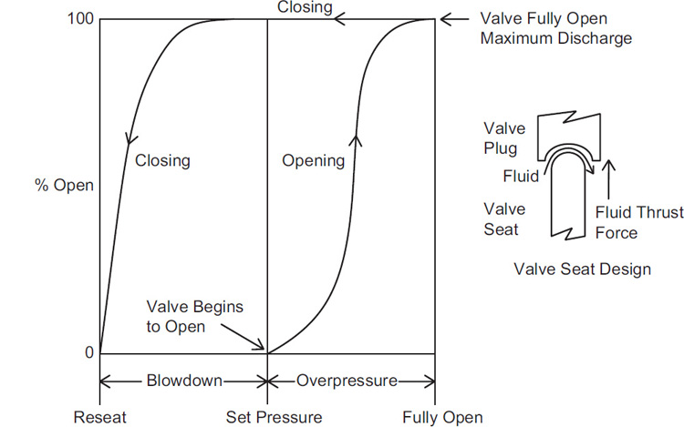
The blowdown is also a function of the type of fluid flowing through the relief device. Liquid flow will result in a large upward thrust force due to the high momentum of the liquid, such that the valve will reseat at a lower pressure. If the fluid is a gas or vapor, the momentum of the flowing fluid through the valve seat is lower and the valve will reseat at a higher pressure. Blowdown must be considered in the design of any downstream effluent system, as it results in additional fluid discharge.
Chatter is the rapid, alternating opening and closing of a spring-operated relief valve. It results in vibration of the valve, which may cause misalignment, valve seat damage, and, if prolonged, mechanical failure of valve internal components and associated piping. Chatter may occur in either liquid or vapor service. The major causes of chatter are excessive inlet pressure drop, excessive built-up back pressure, an oversized valve, and a valve handling widely differing flow rates. Spring reliefs operated at less than 10% overpressure are also likely to chatter.
A simple example will demonstrate how chatter can occur. Consider a spring-operated relief device with inlet piping having a small diameter. When the valve begins to open at the set pressure, fluid starts to flow out of the valve. The flow of fluid through the small-diameter pipe causes a pressure drop across the length of small piping. If this pressure drop across the small piping is large enough, the valve will close since the pressure on the valve plug will drop below the valve reseat pressure. The valve will stay closed until the fluid flow through the pipe again brings the valve up to the set pressure. This cycle will repeat resulting in chatter.
Spring-operated relief performance is affected by backpressure. For a conventional relief device, the set pressure depends on the pressure difference across the valve plug. Thus, backpressure will result in an additional pressure applied to the back of the valve plug that is additive to the spring force. This increases the set pressure, potentially having a negative impact on the valve performance. The backpressure will also reduce the flow through the valve since the flow is proportional to the pressure drop across the valve seat.
The balanced bellows relief device has a bellows on the back side of the valve plug, which reduces the effect of backpressure on the set pressure. For this type of relief device, the set pressure depends on the pressure difference between the pressure on the process side of the valve plug and the vented side of the bellows on the valve plug. Thus, for a balanced bellows relief, backpressure will have a reduced effect on the set pressure, but the flow through the relief will be reduced due to backpressure as a result of a reduced pressure difference across the valve seat.
In a balanced bellows relief, the bellows is susceptible to fatigue or rupture. However, this component does protect the valve spring from exposure to process fluids, thereby reducing corrosion.
Spring-operated relief devices are frequently classified as pop-acting or modulating. When a pop-acting valve opens, the relief rate remains at the valve capacity until the pressure drops and the valve closes. Thus, pop-acting valves are essentially “on/off” devices. In contrast, when a modulating valve opens, the relief rate is the required rate from the process and will increase as the pressure increases until the relief rate is at full capacity.
Rupture Discs
A rupture disc is a thin diaphragm—generally a solid metal disc—designed to rupture or burst at a designated pressure. It is used to protect process equipment against excessive positive or negative pressures. Rupture discs have no moving parts and are simple, reliable, and faster than other relief devices.
Rupture discs are often used as the primary pressure relief device for situations in which pressure can rise very rapidly, as in a runaway reaction, or when a pressure relief valve cannot respond quickly. They are also used in situations where a very large-diameter relief is required and a spring-operated relief is either not available in this size or too expensive.
The major problem with rupture discs is that once they burst, they remain open. This may lead to substantial or total discharge of the process material. It may also allow air to enter the process, leading to a possible fire or explosion with flammable materials.
In addition, a rupture disc may potentially burst without the process operator being aware of this situation. Some rupture discs are available with embedded wires that are cut when the disc bursts; this activates an alarm in the control room to alert the operator.
Rupture discs can also be installed below a spring-operated relief. This design both provides corrosion protection for the spring relief and prevents weeping through the spring relief, which might otherwise result in loss of toxic or expensive process materials. Thus, this setup can reduce fugitive emissions and help the process meet environmental requirements. When a rupture disc is installed below a spring-operated relief, a pressure gauge is typically installed between the two relief devices. This telltale gauge provides an indication of disc rupture or leak. Pressure between the rupture disc and the spring-operated relief will cause the rupture disc to burst at a higher set pressure. Sometimes electronic pressure sensors are used instead of a gauge to alert the operator in the control room to this type of rupture.
When a rupture disc bursts, pieces of the disc metal may become dislodged, creating potential downstream plugging problems. This was a bigger problem years ago, but modern rupture discs are designed to minimize this issue.
Rupture discs cannot be operated very close to the rupture pressure because the metal begins to fatigue. A classic alligator pattern is typically found on the metal of these discs.
These discs are also susceptible to pressure cycling fatigue. The devices will flex with changes in process pressures, and repeated flexing over a period of time may lead to premature failure. The rupture disc may need to be replaced periodically if pressure cycling is a problem.
The burst pressure for rupture discs cannot be tested without destroying the disc. Manufacturers typically manufacture several discs with the same specifications and burst pressure; they then test several to ensure that the remaining discs will operate properly.
Another problem with rupture discs is that the burst pressure will change with temperature.
Rupture discs are installed in a carrier assembly, as shown in Figure 9-4. The carrier assembly clamps the rupture disc in place and provides a leak-tight, metal-to-metal seal. Mechanical damage to the disc may occur if it is not installed properly.
Buckling or Rupture Pin Reliefs
Figure 9-6 depicts a buckling or rupture pin relief device. The valve plug is held in place against the valve seat by a metal rod called the buckling pin. An O-ring is used in the valve seat to ensure a good seal.

As the pressure increases in the process, more force is applied to the pin in this type of relief. Eventually, the pin buckles and the valve opens. One major advantage of using a buckling pin is that the pin buckles at a very precise pressure. However, once the pin buckles, the valve remains open—a disadvantage of these devices.
Buckling pin reliefs have several advantages over rupture discs. First, they are not subject to premature failure due to pressure cycling fatigue. They can also be operated closer to the set pressure, and the set pressure is insensitive to temperature. Resetting the seat after relief activation can also be done without breaking any flanges. Replacement pins are one-third to one-fourth the cost of a rupture disc.
Buckling pin reliefs are available in unbalanced and balanced configurations. They are also available with set pressures as low as 0.1 psig (0.007 barg).
Buckling pin reliefs have two notable disadvantages. First, the elastomer O-ring limits the chemical compatibility and the operating temperature to about 450°F (230°C). Second, the initial cost of installation is greater than that for a rupture disc.
Pilot-Operated Reliefs
Figure 9-7 illustrates a pilot-operated relief. The pilot valve, shown at the top of Figure 9-7, senses the process pressure and maintains pressure behind the valve plug. When the set pressure is reached, the pilot valve opens, decreasing the pressure behind the valve plug and opening the valve. The pilot and main valves reseat when the process pressure drops below the set pressure. The pilot exhaust can be vented either externally or to the main valve outlet.

Pilot-operated reliefs have a valve plug with a larger area on the pilot side than the process side of the plug. This results in a net force holding the valve plug tightly against the valve seat. Thus, pilot-operated relief valves can operate very close to the set pressure—frequently within 98% of that pressure. They are also not affected by backpressure, and some models are less susceptible to chatter.
A backflow preventer may be required when the possibility exists that a higher pressure may occur on the outlet side of the valve than the inlet side.
Pilot valves are sensitive to plugging, so they are typically used in clean service. They also have limited chemical compatibility and temperature range due to the O-ring seals used in the seat. Vapor condensation and liquid accumulation above the piston may cause problems.
Example 9-1
Figure 9-8 shows a semi-batch polymerization reactor process. The major steps in this process include:
Pumping 100 pounds of initiator into reactor R-1.
Heating the reactor to a temperature of 240°F.
Adding monomer for a period of 3 hours. Because the reaction of the monomer is exothermic, thereactor internal coils remove the reaction energy by cooling water. The rate of heat release from the reaction is controlled by the monomer feed rate.
Stripping the residual monomer by means of a vacuum using valve V-15.
For this reaction system,
Identify the equipment that must be protected by a relief.
Identify the relief scenarios.
Determine the type of relief required for each location.

Solution
Parts (a), (b), and (c) are only a small part of the complete relief design procedure, shown in Table 9-2.
Figure 9-9 shows the locations of the reliefs:
Reactor (R-1): A relief is required since this is a pressure vessel. This is labeled PSV-1.
Positive displacement pump (P-1): Positive displacement pumps, if deadheaded, may overload, overheat, and become damaged. The manufacturer’s specifications must be checked—it might have an internal relief. No relief was found on the spec sheets, so a relief (PSV-2) is required.

Figure 9-9 Example 9-1 polymerization reactor with safety reliefs. Heat exchanger (E-1): Heat exchanger tubes can rupture due to excessive pressures when cooling water is blocked in (V-10 and V-11 closed) and the exchanger is exposed to heat from the hot reactor vapor. This is relief PSV-3.
Drum (D-1): This is a pressure vessel, so a relief is required (PSV-4).
Reactor cooling coil: If the coil is full of cooling water and valves V-4, V-5, V-6, and V-7 are closed, and the coil is then heated by the reactor contents, the water will expand and damage the coils (PSV-5).
Pump P-2 does not require a relief since it is a centrifugal pump and the manufacturer’s specs state that a relief is not required.
The relief scenarios are summarized in Table 9-5:
PSV-1a and PSV-1b: There are five scenarios for the reactor: (a) the vessel is full of liquid and pump P-1 is turned on; (b) the cooling coil breaks and water enters at 200 gpm and 50 psig; (c) the nitrogen regulator fails, flooding the reactor with 100 psig nitrogen; (d) loss of coolant during reaction creates a runaway; and (e) fire occurs external to the reactor.
PSV-2: If V-1 is closed, the pump will be deadheaded, causing possible damage to the pump. The relief must handle a flow of 100 gpm at 50 psig.
PSV-3: The blocked-in heat exchanger water coils may potentially experience liquid thermal expansion.
PSV-4: There is only one scenario for the drum (D-1)— nitrogen regulator fails with V-12 open. R-1 scenarios are handled with relief PSV-1.
PSV-5: Water is blocked into the reactor coil and the reactor contents become heated, expanding the water and damaging the coil.
Table 9-5 Relief Scenarios for Example 9-1
Relief identifications
Scenarios
PSV-1a and PSV-1b
(a) Vessel full of liquid and pump P-1 is accidentally actuated.
(b) Cooling coil is broken and water enters at 200 gpm and 50 psig.
(c) Nitrogen regulator fails, giving critical flow through 1-in. line.
(d) Loss of cooling during reaction (runaway).
PSV-2
V-1 is accidentally closed; system needs relief for 100 gpm at 50 psig.
PSV-3
Confined water line is heated with 125-psig steam.
PSV-4
(a) Nitrogen regulator fails, giving critical flow through 0.5-in. line.
(b) Note: The other R-1 scenarios will be relieved via PSV-1.
PSV-5
Water blocked inside coil, and heat of reaction causes thermal expansion.
The types of reliefs are as follows:
PSV-1a is a rupture disc to protect PSV-1b from the reactive monomers that might polymerize and plug PSV-1b.
PSV-1b is a spring-operated relief. Two-phase flow is likely due to the exothermic polymerization reaction.
PSV-2 is a conventional spring-operated relief valve in liquid service.
PSV-3 is a conventional spring-operated relief valve in liquid service.
PSV-4 is a balanced bellows spring-operated relief. Liquid or vapor service is possible here. Backpressure is expected since the relief discharge will require a downstream effluent handling system.
PSV-5 is a conventional spring-operated relief in liquid service only.
Advantages and Disadvantages of Various Reliefs
The major advantages and disadvantages of the different types of reliefs are identified in Table 9-6.
Table 9-6 Major Advantages and Disadvantages of Reliefs
Type of relief |
Advantages |
Disadvantages |
|---|---|---|
Spring-operated (conventional) |
Very reliable Used in Reseats at pressures below the set pressure |
Set pressure affected by backpressure Relief flow reduced by backpressure Chatter possible |
Spring-operated (balanced bellows) |
Set pressure affected less by backpressure Bellows protects spring from corrosion |
Flow is reduced by backpressure Bellows may fatigue/rupture Chatter possible |
Rupture discs |
Simple, reliable, fast No fugitive emissions (i.e., no seal leakage) Low cost and easy to replace Good for high-volume releases Less fouling or plugging Good for second relief requiring large relief area |
Not reclosing—stays open Burst pressure is a function of temperature Burst pressure cannot be directly tested Requires periodic replacement Sensitive to mechanical damage Fatigue problems with pressure cycling |
Buckling pin |
No fatigue problems Relief set pressure is more accurate than with conventional devices Set pressure is not sensitive to operating temperature Replacing pins is very easy and not expensive |
Not reclosing—stays open Elastomer seals limit chemical compatibility and temperature to about 450°F (232oC) Initial cost is greater than for rupture discs |
Pilot-operated |
Relief pressure is not affected by backpressure Can operate at pressures up to 98% of set pressure Seals tightly even at pressures approaching the set pressure Main valve snaps fully open at low overpressures Less susceptible to chatter Chattering due to backpressure is not possible |
Pilot is susceptible to plugging Limited to the chemical and temperature constraints of the seals Condensation and liquid accumulated above the main piston may cause problems Potential for backflow |
9-6 Relief Installation Practices
Figure 9-10 shows a number of common relief installation practices. These practices are important to ensure that the relief operates as intended. The engineer must take responsibility to ensure that the relief is installed as intended and that changes made during installation and operation do not have an impact on the relief performance.

Relief devices are typically tracked from initial installation until they are taken out of service. Many relief devices—particularly spring-operated reliefs—must be recertified on a regular basis, usually annually. The relief device must be removed from service, disassembled, cleaned, and then recertified to ensure that it will open at the correct set pressure. Some companies paint the bonnet on the relief device a specific color for the year the reliefs were recertified. This enables plant workers to easily identify relief valves that have not been properly recertified.
9-7 Relief Effluent Handling
Relief systems are now rarely vented to the atmosphere, and only if the effluent is not hazardous and can be vented to a safe location. Total containment systems are now commonly used.
Figures 9-11 and 9-12 show typical relief containment systems. In Figure 9-11, the reactor discharges a two-phase liquid–vapor mixture. The mixture is first discharged to a blowdown or knockout drum. This horizontal knockout drum serves as a vapor–liquid separator as well as a hold-up tank for the disengaged liquid. The two-phase mixture enters at one end, and the vapor leaves at the opposite end. The treatment of the vapor depends on the properties of the vapor and may include a condenser, scrubber, incinerator, flare, or combination thereof.


Figure 9-12 shows an effluent handling system used when space is limited. The effluent mixture flows first through a tangential knockout drum. The liquid from the drum is discharged to a catch tank, while the vapor is discharged either to the atmosphere or further processing.
Horizontal Knockout Drum
Knockout drums are sometimes called catch tanks or blowdown drums. In Figure 9-11, the horizontal knockout drum system serves as a vapor–liquid separator as well as a hold-up vessel for the disengaged liquid. The two-phase mixture usually enters at one end, and the vapor leaves at the opposite end. Inlets may be provided at each end, with a vapor exit in the center to minimize vapor velocities. When space within a plant is limited, a tangential knockout drum is used, as shown in Figure 9-12.
The design method for sizing this type of system was published by Grossel2 and in API 521.3 The method is based on the maximum allowable velocity for minimizing liquid entrainment.
2S. S. Grossel. “Design and Sizing of Knockout Drums/Catchtanks for Reactor Emergency Relief Systems.” Plant/Operations Progress (July 1986), pp. 129–135.
3API RP 521, Guide for Pressure-Relieving and Depressurizing Systems, 4th ed. (Washington, DC: American Petroleum Institute, 1997), pp. 63–67.
Flares4
4Soen H. Tan. “Flare System Design Simplified.” Hydrocarbon Processing (January 1967), p. 172.
Flares are sometimes used after knockout drums. The objective of a flare is to burn the combustible or toxic gas to produce combustion products that are neither toxic nor combustible. The diameter of the flare must be suitable to maintain a stable flame and to prevent a blowout (when vapor velocities are greater than 20% of the sonic velocity).
The height of a flare is fixed on the basis of the heat generated and the resulting potential damage to equipment and humans. The usual design criterion is that the heat intensity at the base of the stack is not to exceed 1500 Btu/hr ft2. The effects of thermal radiation are shown in Table 9-7.
Table 9-7 Heat Intensity Effects
Heat intensity (Btu/hr ft2) |
Effect |
|---|---|
5300 |
Blisters in 5 s |
3000–4000 |
Vegetation and wood are ignited |
2000 |
Blisters in 20 s |
350 |
Solar radiation |
Scrubbers
The fluid from reliefs, which is sometimes a two-phase flow, must first go to a knockout system, where the liquids and vapors are separated. Liquids are subsequently collected, and the vapors may or may not be vented. If the vapors are nontoxic and nonflammable, they may be vented unless regulation prohibits this type of discharge.
If the vapors are toxic or flammable, a flare or a scrubber system may be required. Scrubber systems can be packed columns, plate columns, or Venturi-type systems. Details of scrubber designs are covered by Treybal.5
5R. E. Treybal. Mass Transfer Operations, 3rd ed. (New York, NY: McGraw-Hill, 1958).
Condensers
A simple condenser is another possible alternative for treating exiting vapors. This alternative is particularly attractive if the vapors have a relatively high boiling point and if the recovered condensate is valuable. This alternative should always be evaluated because it is simple and usually less expensive, and because it minimizes the volume of material that may need additional post-treatment. The design of condenser systems is covered by Kern.6
6D. Q. Kern. Process Heat Transfer (New York, NY: McGraw-Hill, 1950).
Suggested Reading
General Articles on Relief Valves and Systems
AICHE Center for Chemical Process Safety. Guidelines for Pressure Relief and Effluent Handling Systems, 2nd ed. (New York, NY: American Institute for Chemical Engineers, 2017).
American Institute for Chemical Engineers. Emergency Relief System Design Using DIERS Technology (New York, NY: American Institute for Chemical Engineers, 1992).
Ron Darby. “Relief Vent Sizing for Deflagrations.” Process Safety Progress 25, no. 2 (June 2006): 130–134.
D. Green and M. Southard, eds. Perry’s Chemical Engineering Handbook, 9th ed. (New York, NY: McGraw-Hill, 2018), Section 23 on Process Safety.
M. A. Malek. Pressure Relief Devices, ASME and API Code Simplified (New York, NY: McGraw-Hill, 2006).
G. A. Melhem. “Relief System’s Last Line of Defense, Only Line of Defense?” Process Safety Progress 25, no. 4 (2006): 290–297.
Problems
9-1. What is wrong with each of the relief configurations in Figure 9-13? Be specific.

9-2. Review Figure 9-14 and determine (a) the equipment that must be protected by a relief, (b) the relief scenarios for each relief device, and (c) the type of relief required for each location.

9-3. Review Figure 9-15 and determine (a) the equipment that must be protected by a relief, (b) the relief scenarios for each relief device, and (c) the type of relief required for each location.

9-4. Give four examples of situations requiring a combination of spring-operated reliefs in series with rupture discs.
9-5. Develop sketches of reactor relief systems for the following four cases:
|
Case a |
Case b |
Case c |
Case d |
|---|---|---|---|---|
Reactor relief is vapor only |
x |
|
|
x |
Reactor relief is two-phase flow |
|
x |
x |
|
Reactor contents are corrosive |
|
x |
|
x |
Reactor contents are plugging type |
|
x |
|
|
Relieved vapors are toxic |
x |
|
|
x |
Relieved vapors are high boilers |
x |
x |
|
|
Relieved vapors are low boilers |
|
|
x |
x |
9-6.Spring-operated relief valves must be recertified, typically on an annual basis. This requires removal of the relief device from the vessel. One approach is to place a manual valve before the relief so that the relief valve can be easily removed. What is wrong with this approach? What other approach can be used?
9-7. Describe the process of creating a vacuum in a storage vessel as a result of condensation. Develop an example to illustrate the potential magnitude of the vacuum.
9-8. Decide which types of relief devices and configuration should be used for the following situations. Explain.
The process fluid is highly toxic.
The process operates close to the MAWP of the vessel.
The process fluid tends to polymerize and plug.
A very large relief is required.
Two relief scenarios are identified: runaway reaction requiring a very large relief and a relief for more routine and much lower-pressure excursions.
The process has regular and large pressure cycles.
The fluid in the process contains liquid with small-diameter solid particles.
The process and vessel operate at very high pressures.
A high-pressure scenario occurs very quickly.
The process is at a high temperature.
The relief discharges into a header with pressure fluctuations due to other activities elsewhere in the plant.
The relief must discharge a high volume of fluid.
Additional homework problems are available in the Pearson Instructor Resource Center.