
Chapter 11. Hazards Identification and Evaluation
The learning objectives for this chapter are to:
Define terms related to hazard identification and risk assessment.
Describe the hazard identification and risk assessment procedure.
Identify the various methods available for hazard identification/evaluation and risk assessment.
Describe several commonly used methods for hazard identification/evaluation.
Hazards are everywhere. Unfortunately, a hazard is not always identified until an incident occurs. It is essential to identify hazards and reduce risks to prevent incidents.
For every process in a chemical plant, the following questions must be asked:
What are the hazards?
What can go wrong and how?
How bad could it be?
How often could it happen?
What is the risk?
How do we control and manage this risk?
The first question represents hazard identification. The second and third questions are part of hazard evaluation/analysis. Question 4 estimates the likelihood (frequency of occurrence or the probability). Question 5 combines the results of questions 3 and 4 to estimate the risk—a process called risk analysis. Question 6 focuses on risk assessment; it concerns decisions that are made to reduce the risk to a tolerable level based on the results of the previous questions.
In Chapter 1, Table 1-1 included important definitions related to this chapter’s content: hazard identification, hazard evaluation/analysis, risk analysis, and risk assessment. Note that hazards identification identifies the hazards, hazard evaluation/analysis determines the mechanisms and consequences of a potential incident, risk analysis estimates the likelihood and combines this with the consequences to estimate the risk, and risk assessment applies the results of the risk analysis to make decisions. Hazard evaluation/analysis is frequently called process hazards analysis (PHA).
Figure 11-1 shows the procedure for hazards identification and evaluation (covered in this chapter) and risk analysis/assessment (covered in Chapter 12). This procedure can be performed at any stage during the design or operation of a plant. If the study is performed during the process design stage, it should be done as soon as possible before major decisions are made; this enables safety improvements to be easily incorporated into the design.

The procedure in Figure 11-1 begins with a detailed description of the process. The more detailed and reliable the information, the better the result. Next, the hazards are identified for both material and process hazards using a number of procedures presented in this chapter. Hazard evaluation involves identifying the incidents (what can go wrong and how) and incident outcomes (consequences). Risk analysis involves estimating the ultimate loss and harm of the incident (impact) and the likelihood (probability or frequency). The impacts and likelihood are combined to estimate the risk.
Risk assessment involves applying the results of the risk analysis to make decisions. These decisions involve risk tolerance. Risk tolerance is the willingness of a company, and society as a whole, to live with a risk so as to secure the resulting benefits. A risk worth taking is one that is carefully managed and properly controlled. Each company and organization must develop its own risk tolerance. Tolerable risks are chosen by the company’s senior management and are based on industrial experience, judgment, and criteria.1 (See Section 1-9.)
1AICHE Center for Chemical Process Safety. Guidelines for Developing Quantitative Safety Risk Criteria (Hoboken, NJ: Wiley Interscience, 2009).
If the risk is not considered tolerable, modifications must be made and the procedure of Figure 11-1 restarted from the beginning. The modifications could include a change in chemicals, process design, hardware, procedures, and many other aspects. All opportunities for inherently safer designs should be considered. Safeguards should also be added at this point.
A very important responsibility is shown at the bottom of Figure 11-1—namely, the responsibility to build management systems to ensure that the process continues to operate at a tolerable level of risk and to make additional risk reductions if possible. The management system should ensure that the hazards identification and risk assessment procedure is maintained throughout the entire lifetime of a process.
11-1 Introduction to Hazard Identification/Evaluation and Risk Analysis
Table 11-1 lists the major methods used in hazard identification/evaluation and risk analysis. The non-scenario-based methods depend on the experience of the review team, while the scenario-based methods use predictive and analytical methods to define specific incident scenarios. The scenario-based methods are much more complex and tedious than the non-scenario-based methods, since the scenarios may be very numerous and must all be explicitly identified.
Table 11-1 Summary of Hazard Identification/Evaluation and Risk Analysis Methods
Non-scenario-based methods: Depend on the experience of the review team. These are covered in Section 11-2. Checklist analysis: A written list of items or procedural steps to check and validate. Safety review: A committee review that identifies plant conditions or operating procedures that could lead to an incident. Inherent safety review: Identifies hazards to find ways to eliminate or reduce hazards. Often incorporated with checklist reviews, what-if, or HAZOP methods. Preliminary hazard analysis: A list of hazards, causes, major effects, and corrective/preventive measures. Relative ranking: Calculates a number that is a relative indication of the hazard/risk. Scenario-based methods: Use predictive and analytical methods to define the incident scenarios. See Section 11-3. Hazard and operability (HAZOP) study:a A careful review of a process to identify deviations from the design or operational intent that can lead to undesired consequences. Fault tree analysis (FTA):b A deductive technique that focuses on one particular incident or main system failure and determines the causes of the incident. Event tree analysis (ET):b Determines all the possible outcomes following the success or failure of protective systems. Failure modes and effects analysis (FMEA):a Tabulates failure modes of equipment and their effects on a system or process. What-if analysis:a A brainstorming approach to ask questions or voice concerns about possible undesired events. What-if/checklist analysis:a Combines what-if analysis with a checklist. Cause–consequence analysis (CCA) and bow-tie analysis:b A blend of the fault tree end event tree methods. Quantitative risk analysis (QRA):b A very rigorous approach using source models, dispersion models, and effect models to calculate risk estimates for every possible scenario. Layer of protection analysis (LOPA):b A simplified form of quantitative risk analysis using order-of-magnitude categories for initiating event frequency, consequence severity, and likelihood of failure of independent protection layers (IPL). LOPA determines the adequacy of safeguards in the context of hazard evaluations. |
aDiscussed in Chapter 11.
bDiscussed in Chapter 12.
Note: Additional, more detailed information on all these methods is found in AICHE/CCPS. Guidelines for Hazard Evaluation Procedures, 3rd ed. (Hoboken, NJ: Wiley Interscience, 2008).
Nine methods for hazards identification/evaluation are covered in this chapter: checklist analysis, safety reviews, inherent safety reviews, preliminary hazard analysis, relative ranking, hazard and operability (HAZOP) studies, failure modes and effects analysis (FMEA), what-if analysis, and what-if/checklist analysis. The first five methods are non-scenario-based evaluations, whereas the last four are scenario-based methods.
Fault tree analysis (FTA), event tree analysis (ET), quantitative risk analysis (QRA), and layer of protection analysis (LOPA) methods are presented in Chapter 12, as these require an estimate of the incident likelihood.
QRA was the method originally used to estimate risk; indeed, it was the only method available many years ago. It uses source models to estimate release rates of materials from the process, dispersion models to estimate downwind concentrations, and effect models to estimate damage, injury, and loss of life. This analysis is applied to every incident scenario identified—and those scenarios may be very numerous. Computer codes are typically used with this approach.
The LOPA method was developed in the late 1990s as a simplified quantitative risk analysis. LOPA is classified as an adequacy of safeguards method. It uses a risk matrix (see Section 1-9) to estimate the order of magnitude for the initiating event frequency, consequence severity, and likelihood of failure of protection layers. LOPA is presented in Chapter 12.
The success of all PHA methods depends on the quantity and reliability of the information used as inputs to the analysis. Table 11-2 lists some of the information requirements. This list is by no means complete and the actual requirements will depend on the specific process.
Table 11-2 Typical Information Requirements for Hazards Identification/Evaluation and Risk Analysis/Assessment
Category |
Information |
|---|---|
Chemicals |
Flammability of gases, liquids, and dusts (see Chapter 6) Gases: LFL, UFL, AIT, MOC, Pmax, (dP/dt)max Liquids: Flash point temperature Dusts: Minimum explosible concentration (MEC), St class, Pmax Minimum ignition energy (MIE) Toxicity, including acute and chronic inhalation, oral, and dermal (see Chapter 2) Exposure limits: TLV, PEL, STEL. IDLH, ERPG, AEGL, etc. Carcinogenicity, mutagenicity, teratogenicity, etc. Reactivity (see Chapter 8) Stoichiometry Kinetic information Maximum pressure Maximum reaction rate Time to maximum rate Energy released Compatibility with other chemicals and contaminants Properties of intermediate and product chemicals Stability in storage Environmental effects, including biodegradability, aquatic toxicity, and environmental persistence Corrosivity Physical properties: Density, heat capacity, molecular weights, enthalpies, etc. |
Equipment |
Process flow diagrams (PFD) Process and instrument diagrams (P&ID) Mass and energy balances Stream temperatures, pressures, and composition Design basis for all equipment Specifications for all equipment, including all vessels and pipes Maximum temperature and pressure Material of construction, including compatibility with chemicals and other materials Manufacturer’s specifications Equipment layout and spacing Equipment maintenance requirements Pressure protection requirements, including relief devices Storage, including type, quantities, and material compatibility Electrical and area classification Control systems, including safety instrumented systems Control rooms Sampling stations Ancillary equipment, including compressors, electrical supply, water supply, heating and cooling, ventilation, sewage, etc. Emergency response, including personal protection equipment (PPE); sprinklers, deluge and water supply systems; safety showers and eyewash systems; etc. |
Procedures |
Documentation, validated and up-to-date Construction Startup Operation Cleaning Maintenance Pressure testing Mechanical testing Calibration Replacement in kind Safe work procedures, including lock-out/tag-out (LOTO), management of change (MOC), hot work permits, etc. Shutdown Decommissioning Emergency response Training Audits Chemical handling Inerting and purging PHA revalidation Waste disposal Quality control |
Conditions |
Temperature Pressure Concentration Industrial hygiene conditions such as chemical exposures, noise, thermal and ionizing radiation Static electricity formation |
Note: This is only a partial list; specific requirements will vary considerably.
Table 11-3 shows the major phases in the development of a process, along with example hazard objectives and typical PHA and risk analysis methods that are appropriate for each phase. The bottom row of Table 11-3 shows methods that can be applied to incident investigations—a special and (one hopes) rare case in a process lifetime.
Table 11-3 Example Hazard Identification/Evaluation Objectives and Methods at Different Stages in a Process Lifetime
Process phase |
Example hazard identification/evaluation objectives |
Typical hazard evaluation or risk analysis method |
|||
|---|---|---|---|---|---|
Research and development |
Identify chemical reactions or chemical incompatibilities that could cause runaway reactions, fires, explosions, or toxic gas releases. Identify process safety data needs for future analysis. |
Inherent safety review Hazards inventory/survey Relative ranking Preliminary hazard analysis |
|
||
Conceptual design |
Select process technology based on inherent safety. Identify other opportunities for inherent safety. Compare the hazards between potential plant sites. Provide input to facility layout and buffer zones. |
Inherent safety review Checklist analysis Relative ranking Preliminary hazard analysis |
What-if What-if/checklist Inherent safety review LOPA |
||
Pilot plant |
Identify ways for hazardous materials to be released to the environment. Identify ways a catalyst can be deactivated. Identify potentially hazardous operator interfaces. Identify ways to minimize hazardous wastes. |
Checklist analysis Preliminary hazard analysis What-if What-if/checklist HAZOP Bow-tie |
FMEA Fault tree Event tree Cause–consequence analysis LOPA |
||
Detailed engineering |
Identify ways for a flammable mixture to form inside process equipment. Identify how a reportable spill might occur. Identify which process control malfunctions will cause runaway reactions. |
Inherent safety review Checklist analysis Preliminary hazard analysis What-if |
FMEA Fault tree Event tree Cause–consequence analysis QRA |
||
|
Identify ways to reduce hazardous material inventories. Evaluate whether designed safeguards are adequate to control process risks to required levels. Identify safety critical equipment that must be regularly tested, inspected, or maintained. |
What-if/checklist HAZOP |
LOPA Bow-tie |
||
Construction and startup |
Identify error likely situations in the startup and operating procedures. Verify that all issues from previous hazard evaluations were resolved satisfactorily and that no new issues were introduced. Identify hazards that adjacent units may create for construction and maintenance workers. Identify hazards associated with vessel cleaning procedures. Identify any discrepancies between as-built equipment and the design drawings. |
Safety review Checklist analysis What-if What-if/checklist |
|
||
Routine operation |
Identify hazards associated with operating procedures. Identify ways an overpressure transient might occur. Update previous hazard evaluations to account for operational experience. Identify hazards associated with out-of-service equipment. Ensure that maintenance is done on time and safely. Implement safe work practices for nonroutine operations such as hot work, lock-out/tag-out (LOTO) operations, and others. |
Inherent safety review Safety review Checklist analysis What-if What-if/checklist HAZOP Bow-tie |
FMEA Fault tree Event tree Cause–consequence analysis QRA LOPA |
||
Process modification or plant expansion |
Identify whether changing the feedstock composition will create any new hazards or worsen existing ones. Identify hazards associated with new equipment. |
All methods |
|
||
Decommissioning |
Identify how demolition work will affect adjacent units. Identify any fire, explosion, or toxic hazards associated with any residues left in the unit after shutdown. |
Safety review Checklist analysis |
What-if What-if/checklist |
||
Incident investigation |
As required. |
What-if HAZOP FMEA Fault tree Bow-tie |
Event tree Cause–consequence analysis QRA |
||
Source: Adapted from AICHE/CCPS. Guidelines for Hazard Evaluation Procedures, 3rd ed. (Hoboken, NJ: Wiley Interscience, 2008).
PHA and risk analysis/assessment methods are applied throughout the process lifetime. Certainly, they must be applied as early as possible during the early phases of the process lifetime. They are also applied on a fixed time frame—for example, annually. They are also applied as needed—for example, if changes are made to the process, if a “near miss” occurs, or if a leading or lagging indicator reveals that the hazards were not appropriately identified or controlled.
An important decision is which method to select. Table 11-4 lists some factors that influence the selection of a method. The selection depends on the phase of the process and on a number of influencing factors, such as the motivation for the study, type of results required, type of information available to perform the study, characteristics of the analysis problem, perceived risk, and resource availability.
Table 11-4 Factors That Influence the Selection of a Hazard Identification/Evaluation or Risk Analysis Method
|
Source: Adapted from AICHE/CCPS. Guidelines for Hazard Evaluation Procedures, 3rd ed. (Hoboken, NJ: Wiley Interscience, 2008).
11-2 Non-Scenario-Based Hazard Identification/Evaluation Methods
Non-scenario-based methods depend on the experience of the review team.
Checklist Analysis
A checklist analysis uses a list of possible problems, hazards, or procedural steps to be reviewed and verified. The analysis reminds the reviewers to consider specific issues to decide if they are addressed appropriately.
The checklist review is most suitable during the conceptual design, pilot plant, detailed engineering, construction and startup, routine operation, process modification or plant expansion, and decommissioning stages of a plant life cycle, as shown in Table 11-3. However, the checklist analysis is best applied in the preliminary stages of hazard identification; it should not be used as a replacement for a more detailed hazards identification/evaluation method.
The checklist used varies widely in detail and may include hundreds or even thousands of items. Checklist analysis can be used to evaluate materials, equipment, or procedures. Checklists can be customized for specific processes, specific types of process equipment (e.g., heat exchangers, pumps, distillation columns), and different stages in the lifetime of a plant.
A typical checklist is shown in Figure 11-2. This checklist has three checkoff columns. The first column is used to indicate those areas that have been thoroughly investigated. The second column is used for those items that do not apply to the particular plant. The last column is used to mark those areas requiring further investigation. Extensive notes on individual areas are kept separate from the checklist.

Checklist analysis includes three steps:2
2AICHE Center for Chemical Process Safety. Guidelines for Hazard Evaluation Procedures, 3rd ed. (Hoboken, NJ: Wiley Interscience, 2008).
Select and develop an appropriate checklist. Experienced team members start with available checklists, such as Figure 11-2. These checklists are enhanced with industrially available checklists. Available checklists from previous or other studies can be updated to include the latest codes, standards, regulations, and practices. If an appropriate checklist cannot be identified, one can be developed using the experience of the team.
Perform the checklist analysis. The review is conducted using plant tours, interviews, and document reviews. During these activities, the analysts compare the process equipment and operations to the checklist items. The recognized deficiencies are discussed by the team to develop recommendations.
Document the results. The final report includes the checklists used in the review, the noted deficiencies, recommendations, and justifications.
Checklist analysis can also be used to enhance other hazard evaluation methods, such as the what-if method.
Safety Reviews
The safety review was perhaps the earliest hazard evaluation method. It can be used for laboratory, pilot plant, and large process scale equipment. It can be used for new processes, substantial changes in existing processes, and processes that have not been reviewed recently. The success of the safety review strongly depends on the expertise of a safety review committee.
Safety reviews are typically performed during the following phases in a plant’s lifetime (see Table 11-3): construction/startup, routine operation, process modification or plant expansion, and decommissioning. They have the following purposes:
Identify and alert operating personnel to the presence of process hazards
Review operating procedures
Identify equipment or process changes that may have introduced new hazards
Evaluate the design basis of control systems, instrumented protective systems, and emergency relief systems
Review the application of new technology to existing hazards
Review the adequacy of maintenance and safety systems2
Often a safety review will identify the need for a more detailed review, such as other methods described in the scenario-based methods shown in Table 11-1.
After startup, safety reviews should be conducted on a periodic basis or whenever changes are made to the process, procedures are modified, a “near miss” occurs, or if leading or lagging indicators reveal a deficiency.
The safety review process includes the following steps:3
3AICHE Center for Chemical Process Safety. Guidelines for Hazard Evaluation Procedures, 3rd ed. (Hoboken, NJ: Wiley Interscience, 2008).
Prepare for the review. A team is formed and given the responsibility for the review. The review team should include operators, maintenance workers, process engineers, and instrument specialists. Other specialists should be available for answering specific technical questions. One or more of the team members are assigned the responsibility to gather relevant information, including sketches; process flow diagrams (PFDs); process and instrument diagrams (P&IDs); equipment specifications; process chemicals and their hazardous properties; codes, standards, and procedures for operation; maintenance; emergency procedures; and other available information. Recommendations from previous safety reviews are also obtained, if available.
Make additional preparations and perform the review. Team members are assigned to tour the facility; interview people with detailed knowledge of the chemistry, engineering requirements, plant controls, and equipment (including reaching out to other sites and companies); review inspection results and the status of previous safety review recommendations; review incident investigation reports and the status of recommendations; and gather and evaluate other relevant and available information. When this is completed, the team meets to review these results. This meeting is used to identify hazards, evaluate the outcomes, and decide how the hazards are addressed.
Document the results. After the review, the team develops a report and recommendations with appropriate justifications. Prior to publication, the recommendations are reviewed with management. The final approved recommendations are included in the final safety review document.
Inherent Safety Reviews
Inherent safety was discussed in Section 1-13. Inherent safety reviews evaluate the plant to identify ways to prevent incidents by eliminating or reducing hazards rather than by adding more control systems, interlocks, redundancy, and special operating procedures.
Inherent safety reviews, as shown in Table 11-3, are most suitable during research and development, conceptual design, detailed engineering, routine operation, and process modification or plant expansion stages of a process lifetime.
The steps in an inherent safety review are as follows:
Collect and review available information.
Define the major hazards.
Systematically review the process at each process step to identify hazards and to determine creative ways to improve the process by applying principles of inherently safer design.
Document the review and follow-up actions.
Inherent safety reviews can be included with other PHA methods or part of a much larger hazard evaluation.
Preliminary Hazard Analysis
A preliminary hazard analysis (not to be confused with the acronym PHA used for process hazard analysis) focuses in a general way on the hazardous materials and major process areas in the plant. It formulates a list of hazards and incident scenarios by considering various process characteristics. It can also identify alternative design criteria that could eliminate or reduce the hazards. It is specifically intended to discover hazards early in the plant’s life, so information may be limited. The review team must, at least, have a written general description of the conceptual design, some chemistry and reactions, and major equipment.
Preliminary hazard analysis is suitable for the research and development, conceptual design, pilot plant, detailed engineering, and process modification or plant expansion of a process lifetime, as shown in Table 11-3. It includes the following steps:
Prepare for the review. Form the team, drawing on available experience from many sources. Gather available information about the process, including information and operating experience from a similar plant.
Perform the review. Consider hazardous materials and plant equipment (e.g., fuels, reactive chemicals, high-pressure systems); safety-related interfaces between the plant equipment and materials (human error); environmental factors (e.g., earthquakes, floods); operating, testing, maintenance, and emergency procedures; facility support; and safety-related equipment.
Document the results. The resulting preliminary hazard analysis worksheet has the following columns:
Hazards identified
Initiating causes (e.g., mechanical failure, procedural error, external force, raw material variation, or environmental condition)
Major effects or consequences (e.g., potential for injuries or fatalities)
Hazard category or a priority using the following scale: Hazard Category I (negligible), Hazard Category II (marginal), Hazard Category III (critical), and Category IV (catastrophic)
Corrective/preventive measures, such as the application of inherently safety design (eliminate or reduce hazards); safeguards, both preventive and mitigative
Relative Ranking
Relative ranking methods calculate a number or index that is indicative of the hazards in the process. They are excellent choices for comparing various process alternatives or deciding if a more rigorous PHA method is required. These methods are most suitable during the research and development, conceptual design, and process modification or plant expansion phases of a process lifetime, as shown in Table 11-3.
The most popular relative ranking methods are the Dow Fire and Explosion Index (F&EI) and the Dow Chemical Exposure Index (CEI). Both of these approaches use formal systematized approaches based on a rating form, similar to an income tax form. The final number provides a relative ranking of the hazard.
The F&EI is designed for rating the relative hazards with the storage, handling, and processing of flammable materials. The procedure begins with a material factor, which is a function only of the chemical. The material factor is first adjusted for general and special process hazards—for example, storage above the flash or boiling point, endothermic or exothermic reactions, and fired heaters. Credits for various safety systems and procedures are then applied for estimating the consequences of the hazard. The F&EI is also capable of estimating a dollar value for property damage.
The CEI is a relative ranking method for rating the acute health hazard potential for people in neighboring communities or plants arising from possible chemical release. The procedure begins with identification of possible release incidents, such as releases from pipes and hoses; pressure relief devices relieving directly to the atmosphere; releases from vessels; and tank overflows and spills. The incidents are used with a number of simplified source models provided in the CEI guide to estimate the release rate of material. The Emergency Response Planning Guidelines (ERPG) are then used with a simplified dispersion model to determine the CEI value and downwind hazard distances resulting from the release.
The sum of both the F&EI and CEI numbers for a specific process can be used to decide if a more rigorous PHA method is required.
Example 11-1
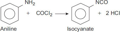
Consider the laboratory reactor system shown in Figure 11-3. This system is designed to react phosgene (COCl2) with aniline to produce isocyanate and HCl. The reaction is shown in Figure 11-4. The isocyanate product is used for the production of foams and plastics.

Phosgene is a colorless vapor with a normal boiling point of 46.8°F. Thus, it is usually stored as a liquid in a container under pressure above its normal boiling point temperature. The TLV-TWA for phosgene is 0.1 ppm, and its odor threshold is 0.55 ppm, well above the TLV-TWA.
Aniline is a liquid with a boiling point of 364°F. Its TLV-TWA is 2 ppm. It is absorbed through the skin.
In the process shown in Figure 11-3, phosgene is fed from the supply container through a valve into a fritted glass bubbler in the reactor. The reflux condenser condenses the aniline vapors and returns liquid aniline to the reactor. A caustic scrubber is used to remove the phosgene and HCl vapors from the exit vent stream. The complete process is contained in a hood.
Conduct a safety review of this process.
Solution
The safety review was completed by two individuals—the process is simple and small enough that a full committee review is not necessary. The final process design is shown in Figure 11-5. The changes and additions to the process are as follows:
A flow indicator provides a visual indication of the flow. This is a simple bubbler.
A relief system composed of a glass U-tube filled with liquid is added with an outlet to the scrubber. This prevents pressure hazards resulting from a possibly plugged fritted glass bubbler. This relief will operate at a few inches of water gauge pressure.
The trap catches any liquid phosgene that may come from the tank.
The existing scrubber is not very effective at absorbing vapors from a single open tube. This is replaced by two bubblers with caustic and ammonium hydroxide to absorb any phosgene or HCl vapor.
Vacuum is added to reduce the boiling point temperature.
A pail of caustic is added (the phosgene cylinder would be dumped into this pail in the event of a cylinder or valve leak; the caustic would absorb the phosgene).

In addition, the reviewers made the following recommendations: (1) Hang phosgene indicator paper around the hood, room, and operating areas (this paper is normally white but turns brown when exposed to 0.1 ppm of phosgene); (2) develop and use a safety checklist daily, before the process is started; and (3) post an up-to-date process sketch near the process.
11-3 Scenario-Based Hazard Identification/Evaluation Methods
Scenario-based methods use predictive and analytical methods to define the incident scenarios. These methods are relatively complex and are performed by experienced personnel. All scenario-based hazard methods use incident scenarios to determine what can go wrong.
Although industry uses many different methods,4 this chapter will only cover four methods: hazard and operability studies (HAZOP), failure modes and effects analysis (FMEA), what-if analysis, and what-if/checklist analysis.
4AICHE Center for Chemical Process Safety. Guidelines for Hazard Evaluation Procedures, 3rd ed. (Hoboken, NJ: Wiley Interscience, 2008).
Hazard and Operability Studies
The objective of a HAZOP is to systematically identify and evaluate scenario-based hazards in a chemical plant and to identify operability problems that could impact plant productivity. This method results in recommendations to reduce the risk. The basic idea is to let the mind go free in a controlled fashion so as to consider all the possible ways that plant and operational failures might occur. The HAZOP method is suitable for the pilot plant, detailed engineering, routine operation, process modification or plant expansion, and incident investigation stages of a process lifetime, as shown in Table 11-3.
Before the HAZOP study is started, detailed information on the process must be gathered. This includes up-to-date process flow diagrams (PFDs), piping and instrumentation diagrams (P&IDs), detailed equipment specifications, materials of construction, a list of all chemicals and process materials including safety data sheets (SDSs), and mass and energy balances, to name a few. Other information may be important depending on the process. All information must be current and reliable.
The full HAZOP study requires a committee composed of personnel from the plant, laboratory, engineering, maintenance, instrument, and safety departments, to name a few. One individual must be a trained HAZOP leader and serves as the committee chair. This person leads the discussion and must be experienced with both the HAZOP procedure and the chemical process under review. One individual must also be assigned the task of recording the results; a number of vendors provide software to assist with this function.
The committee meets on a regular basis for a few hours at a time. The meeting duration must be short enough to ensure continuing interest and input from all committee members. A large process might take several months of twice-weekly meetings to complete the HAZOP study. Obviously, a complete HAZOP study requires a large investment in time and effort, but the result is worth the effort. Definitions for HAZOP study terms are shown in Table 11-5.
Table 11-5 Definitions for HAZOP Study Terms
Node: A location on a process diagram at which process parameters are investigated for deviations. Node examples are: A pipeline transferring material between two units A specific tank or vessel |
Design intent: Defines how the system is expected to operate at the nodes. It provides a point of reference for developing deviations. All nodes have design intents. The design intents can be imbedded in the HAZOP table or in the HAZOP description (see Example 11-2). |
Parameter: A characteristic of the process that describes it physically, chemically, or in terms of what is happening: Specific parameters: flow, temperature, pressure, etc. General parameters: addition, reaction, maintenance, relief, etc. |
Guidewords: See Tables 11-6 through 11-9. |
Deviations: These irregularities are discovered by systematically applying the guidewords to each parameter at each node (e.g., more + temperature = higher temperature). |
Causes: The reasons why deviations may occur. Causes can be equipment failure, human error, or external events. |
Consequences: Documented as impacts resulting from the loss event. |
Recommendations: Suggested actions to prevent or mitigate the consequence of deviations, or to obtain further information. |
Safeguards: The systems in place that reduce the probability of the deviation occurring or mitigate the severity of the consequences. See Section 1-11. |
Source: Adapted from AICHE CCPS Faculty Workshop. “Hazard Identification and Evaluation.” (Freeport, TX: Dow Chemical Company, June 2017).
The HAZOP procedure uses the following steps to complete an analysis:
Begin with a detailed flow sheet. Divide the flow sheet into a number of process units. Thus, the reactor area might be one unit, and the storage tank area another. Select a unit for study.
Choose a study node, such as vessel, line, or operating instruction. HAZOPs are also used for procedures, especially when human factors may be important—including procedures such as startup, shutdown, emergency operations, and sampling.
Describe the design intent of the study node. For example, vessel V-1 is designed to store the benzene feedstock and provides it on demand to the reactor.
Pick a process parameter: flow, level, temperature, pressure, concentration, pH, viscosity, state (solid, liquid, or gas), agitation, volume, reaction, sample, component, start, stop, stability, power, or inert. Other process parameters might be valid for your particular process.
Apply a guide word to the process parameter to suggest possible deviations. Table 11-6 lists some guide words. Note that some of the guide word process parameter combinations are meaningless, as shown in Table 11-7 for process lines and in Table 11-8 for vessels. Guidelines, associated parameters, and deviations are listed in Table 11-9.
Table 11-6 Guide Words Used for the HAZOP Procedure
Guide words |
Meaning |
Comments |
|---|---|---|
no, not, none |
The complete negation of the intention |
No part of the design intention is achieved, but nothing else happens. |
more, higher, greater |
Quantitative increase |
Applies to quantities such as flow rate and temperature and to activities such as heating and reaction. |
less, lower |
Quantitative decrease |
Applies to quantities such as flow rate and temperature and to activities such as heating and reaction. |
as well as |
Qualitative increase |
All the design and operating intentions are achieved along with some additional activity, such as contamination of process streams. |
part of |
Qualitative decrease |
Only some of the design intentions are achieved; some are not. |
reverse |
The logical opposite |
Most applicable to activities such as flow or chemical reaction. Also applicable to substances—for example, poison instead of antidote. |
other than |
Complete substitution |
No part of the original intention is achieved; the original intention is replaced by something else. |
sooner than |
Too early or in the wrong order |
Applies to process steps or actions. |
later than |
Too late or in the wrong order |
Applies to process steps or actions. |
where else |
In additional locations |
Applies to process locations, or locations in operating procedures. |
Table 11-7 Valid Guide Word and Process Parameter Combinations for Process Lines
Process parameters |
No, not, none |
More, higher, greater |
Less, lower |
As well as |
Part of |
Reverse |
Other than |
Sooner, faster |
Later, slower |
Where else |
|---|---|---|---|---|---|---|---|---|---|---|
Flow |
x |
x |
x |
x |
x |
x |
x |
x |
x |
|
Temperature |
|
x |
x |
|
|
|
|
x |
x |
|
Pressure |
|
x |
x |
x |
|
|
|
x |
x |
|
Concentration |
x |
x |
x |
x |
x |
|
x |
x |
x |
|
pH |
|
x |
x |
|
|
|
|
x |
x |
|
Viscosity |
|
x |
x |
|
|
|
|
x |
x |
|
State |
|
|
|
x |
|
|
|
x |
x |
|
Note: x’s represent valid combinations.
Table 11-8 Valid Guide Word and Process Parameter Combinations for Process Vessels
Process Parameters |
No, Not, None |
More, Higher, Greater |
Less, Lower |
As Well As |
Part of |
Reverse |
Other Than |
Sooner, Faster |
Later, Slower |
Where Else |
|---|---|---|---|---|---|---|---|---|---|---|
Level |
x |
x |
x |
x |
x |
|
x |
x |
x |
x |
Temperature |
|
x |
x |
|
|
|
|
x |
x |
|
Pressure |
|
x |
x |
x |
|
|
|
x |
x |
|
Concentration |
x |
x |
x |
x |
x |
|
x |
x |
x |
|
pH |
|
x |
x |
|
|
|
|
x |
x |
|
Viscosity |
|
x |
x |
|
|
|
|
x |
x |
|
Agitation |
x |
x |
x |
|
x |
x |
|
x |
x |
|
Volume |
x |
x |
x |
x |
x |
|
|
x |
x |
x |
Reaction |
x |
x |
x |
|
|
|
x |
x |
x |
|
State |
|
|
|
x |
|
|
x |
x |
x |
|
Sample |
x |
|
|
x |
x |
|
x |
x |
x |
|
Note: x’s represent valid combinations.
Table 11-9 HAZOP Deviations for Different Guidewords and Parameters
|
Parameters ↓ |
Guidewords |
||||||
|---|---|---|---|---|---|---|---|
More |
Less |
None |
Reverse |
Part of |
As well as |
Other than |
|
Flow |
High Flow |
Low Flow |
No flow |
Backflow |
|
|
Loss of containment |
Pressure |
High pressure |
Low pressure |
Vacuum |
|
Partial pressure |
|
|
Temperature |
High temperature |
Low temperature |
|
|
|
Cryogenic |
|
Level |
High level |
Low level |
No level |
|
|
|
Loss of containment |
Composition or state |
Additional phase |
Loss of phase |
|
Change of state |
Wrong concentration |
Contaminants |
Wrong material |
Reaction |
High reaction rate |
Low reaction rate |
No reaction |
Reverse reaction |
Incomplete reaction |
Side reaction |
Wrong reaction |
If the deviation is applicable, determine possible causes and note any protective systems.
Evaluate the consequences of the deviation (if any).
Recommend action (what? by whom? by when?).
Record all information.
Repeat steps 5 through 9 until all applicable guide words have been applied to the chosen process parameter.
Repeat steps 4 through 10 until all applicable process parameters have been considered for the given study node.
Repeat steps 2 through 11 until all study nodes have been considered for the given section and proceed to the next section on the flow sheet.
Since the HAZOP method is scenario based, multiple scenarios are defined in steps 1 through 7, and the recommendations are developed in step 8.
Note that there are 18 process parameters listed and 10 guide words, so that 180 total combinations are possible for each study node. Thus, the HAZOP procedure produces a huge amount of combinations to consider.
The guide words AS WELL AS, PART OF, and OTHER THAN can sometimes be conceptually difficult to apply. AS WELL AS means that something else happens in addition to the intended design intention. This could be boiling of a liquid, transfer of some additional component, or transfer of some fluid somewhere else than expected. PART OF means that one of the components is missing or the stream is being preferentially pumped to only part of the process. OTHER THAN applies to situations in which a material is substituted for the expected material, is transferred somewhere else, or solidifies and cannot be transported. The guide words SOONER THAN, LATER THAN, and WHERE ELSE are applicable to batch processing.
An important part of the HAZOP procedure is the process required to record and use the results. Many methods can be used to accomplish this, and most companies customize their approach to fit their way of doing things.
Table 11-10 presents one type of basic HAZOP form. The first column, denoted “Item,” is used to provide a unique identifier for each case considered. The numbering system used comprises a number–letter combination. Thus, the designation “1A” indicates the first study node and the first guide word. The second column lists the study node considered. The third column lists the process parameter, and the fourth column lists the deviations or guide words. The next three columns are the most important results of the analysis. The first column lists the possible causes, which are determined by the committee and are based on the specific deviation guide word combination. The next column lists the possible consequences of the deviation. The next column lists the safeguards that currently exist. The final column lists the action required to prevent the hazard from resulting in an incident. Notice that the items listed in these four columns are numbered consecutively. Additional columns can be added to track the work responsibility and the completion of the work.
Example 11-2
Consider the reactor system shown in Figure 11-6. The reaction is exothermic, so a cooling system is used to remove the excess energy of reaction (this is the design intent). In the event that the cooling function is lost, the temperature of the reactor would increase. This would lead to an increase in reaction rate, resulting in additional energy release. The ultimate result would be a runaway reaction with pressures exceeding the bursting pressure of the reactor vessel.

The temperature within the reactor is measured and is used to control the cooling water flow rate with a valve. Perform a partial HAZOP study on this unit to improve the safety of the process. Use the cooling coil as a study node, a process parameter of flow, and the guide words of NO, HIGH, and LOW.
Solution
The guide words are applied to the study node of the cooling coils with the process parameter of flow. The HAZOP results are shown in Table 11-10 (though the table does not contain the complete results of the HAZOP study).
Table 11-10 HAZOP Study Applied to the Exothermic Reactor of Example 11-2
Project name: Example 11-4 |
Date: July 18, 2019 |
Page 1 of 2 |
||||||
|---|---|---|---|---|---|---|---|---|
Process: Reactor of Example 11-4 |
|
|
||||||
Section: Reactor shown in example 11-2 |
Reference drawing: |
|
||||||
Item |
Study node |
Process parameters |
Deviations (Guide words) |
Possible causes |
Possible consequences |
Existing safeguards |
Action required |
|
1A |
Cooling coils |
Flow |
No |
1. Control valve fails closed |
1. Loss of cooling, possible runaway. |
1 & 2. Flow transmitter with low-flow alarm and high-temperature alarm on reactor. |
1. Select valve to fail open. |
|
|
|
|
|
2. Plugged cooling coils |
2. Same as 1. |
|
2. Install filter with maintenance procedure. Install cooling water flow meter and low-flow alarm. Install high-temperature alarm to alert operator. |
|
|
|
|
|
3. Cooling water service failure. |
3. Same as 1. |
3, 4, 5. No safeguards. |
3. Check and monitor reliability of water service. |
|
|
|
|
|
4. Controller fails and closes valve. |
4. Same as 1. |
|
4. Place controller on critical instrumentation list. |
|
|
|
|
|
5. Air pressure fails, closing valve. |
5. Same as 1. |
|
5. See 1A.1. |
|
1B |
|
|
High |
1. Control valve fails open. |
1. Reactor cools, reactant concentration builds, possible sleeping reactor. |
1. No safeguards. |
1. Instruct operators and update procedures. |
|
|
|
|
|
2. Controller fails and opens valve. |
2. Same as 1. |
2. Flow transmitter with high-flow alarm. |
1. Place controller on critical instrumentation list. See 1A.4 |
|
1C |
|
|
Low |
1. Partially plugged cooling coils. |
1. Diminished cooling, possible runaway. |
1. See 1A.1 |
1. See 1A.2 |
|
|
|
|
|
2. Partial water source failure. |
2. Same as 1. |
2. See 1A.1 |
2. See 1A.2 |
|
|
|
|
|
3. Control valve fails to respond. |
3. Same as 1. |
3. No safeguard. |
3. Place valve on critical instrumentation list. |
|
Some of the process modifications resulting from the more detailed study are as follows:
Select the control valve to fail open.
Install a filter to prevent plugging of the cooling coils. Add the filter to the maintenance schedule.
Install a cooling water flow meter and a low-flow alarm (which will provide an immediate indication of cooling loss).
Install redundant temperature indicators and controllers, and include equipment from different vendors to prevent common-cause failures.
Install a high-temperature alarm to alert the operator in the event of cooling loss.
Install a high-temperature shutdown system. This system would automatically shut down the process in the event of a high reactor temperature. The shutdown temperature would be higher than the alarm temperature to provide the operator with the opportunity to restore cooling before the reactor is shut down.
Install a check valve in the cooling line to prevent reverse flow. A check valve could be installed before and after the reactor to prevent the reactor contents from flowing upstream and to prevent the backflow in the event of a leak in the coils.
Periodically inspect the cooling coil to ensure its integrity.
Study the cooling water source to consider possible contamination and interruption of supply.
Consider redundant water and air sources. Nitrogen can be a backup for air and a storage tank of water would back up the water supply.
In the event that the cooling water system fails (regardless of the source of the failure), the high-temperature alarm and emergency shutdown system should prevent a runaway reaction. The review committee performing the HAZOP study decided that the installation of a backup controller and control valve was not necessary. The high-temperature alarm and shutdown system already prevent a runaway reaction in this event.
Similarly, a loss of coolant water source or a plugged cooling line would be detected by either the alarm or the emergency shutdown system. The review committee suggested that all coolant water failures be properly reported and that if a particular cause occurred repeatedly, then additional process modifications would be warranted.
A key advantage of the HAZOP approach is that it provides a more complete identification of the hazards, including information on how hazards can develop as a result of operating procedures and operational upsets in the process. Companies that perform detailed HAZOP studies find that their plants operate better and have less downtime, their product quality is improved, less waste is produced, and their employees are more confident in the safety of the process. The disadvantages are that the HAZOP approach is tedious to apply and requires considerable staff time and effort.
Failure Modes and Effects Analysis
FMEA was one of the first highly structured, systematic techniques for failure analysis. It was developed by reliability engineers in the late 1950s to minimize malfunctions of military systems. This method is used to identify how equipment can fail (or be improperly operated) and its effects on the process. Current safeguards to prevent these failures and the level of risk for each failure are also identified.
The benefits of FMEA include reduced failures by identification and elimination of potential failure modes. FMEA is most suitable for pilot plant, detailed engineering, routine operation, process modification or plant expansion, and incident investigation stages of a process lifetime,5,6 as shown in Table 11-3.
5AICHE Center for Chemical Process Safety. Guidelines for Hazard Evaluation Procedures, 3rd ed. (Hoboken, NJ: Wiley Interscience, 2008), p. 134.
6R. McDermott, R. Mikulak, and M. Beauregard. The Basics of FMEA, 2nd ed. (London, UK: Taylor & Francis Group, 2009).
An FMEA study includes four steps:
Assemble a cross-functional team of three to six knowledgeable people, from functions such as design, research, operations, and maintenance. Select team members who really know and understand the details of the process.
Define the systems to be studied, including the boundaries and the appropriate level of resolution. A P&ID and other plant descriptions will assist with this step. If a plant-level hazard is being addressed, the FMEA should focus on the failure modes of individual systems and their effects. This could include the plant’s feed system, mixing system, separation systems, and support systems. When a system-level hazard is being addressed, the FMEA should focus on the failure modes of individual equipment and their effects on the overall system. This could include the feed pump, mixing motor, control valves, or temperature sensors. Maintenance records providing information on equipment failures and modes are very useful.
Conduct a deliberate and systematic review by using a worksheet like Table 11-11 for Example 11-3.
Identification: A unique identifier that relates to the P&ID, process, or location.
Equipment description: Include characteristics that may influence failure modes (e.g., the air-operated control valve to control cooling water flow fails open).
Failure modes: List all failure modes for each component (e.g., fails open, fails closed, leaks out, leaks internally).
Failure mode causes: Causes may include residue in line, loss of air or nitrogen, corrosion failures, and so on.
Effects: Include local effects and anticipated effects on other equipment or the system (e.g., temperature increases and pressure rises).
Existing safeguards: Existing safety features that decrease the likelihood or mitigate the consequences.
Actions/recommendations: Corrective actions may focus on effects or causes of effects (e.g., consider adding a high-pressure alarm and consider a shutdown system for high pressures). Actions would include new safeguards (preventive, mitigative), steps such as training, and more reliable controls to prevent common cause failures.
Risk level: A knowledgeable team can rate the risk level for each failure mode. This information is used later when deciding which actions should be taken. The risk level is assigned using a scale from 1 = low level to 10 = high level.
Document the results. After the FMEA worksheet is completed, the team evaluates the results and makes decisions to reduce the consequences or likelihood of each of the failure modes. The actions are prioritized based on the risk level.
Example 11-3
Conduct an FMEA for a control valve that adjusts the cooling water flow to control the temperature of a batch reactor containing an exothermic reaction that has the potential to become a runaway reaction.
Solution
The team would recognize that this is just one portion of a system to be analyzed. They would then develop the table of results, shown here as Table 11-11. After the table is developed, the team would analyze the results and include them in a results document.
Table 11-11 FMEA Worksheet for Example 11-3
|
Date: 2/2/2020 Plant: Polyether System: Reactor Cooling |
Team members: John A., Joseph S., and Jacob Z.
|
Page: 1/10
|
A. |
B. |
C. |
D. |
E. |
F. |
G. |
H. |
I. |
|---|---|---|---|---|---|---|---|---|
1A |
B. Air-operated control valve to control reactor temperature |
C. Controls cooling water flow, fails open |
D. Fails open |
E. Loss of air, failed temperature reading |
F. Cools reactor and accumulates monomer, restart could cause runaway |
G. High-flow alarm, low-temperature alarm |
H. Consider redundant temperature reading, redundant source of air, or use nitrogen to back up loss of air |
I. 10 |
1B |
B. Air-operated control valve to control reactor temperature |
C. Controls cooling water flow, fails open |
D. Fails closed |
E. High air pressure, valve spring fails, plugged valve |
F. Reactor temperature increases, poor product quality |
G. Low-flow alarm, high-temperature alarm |
H. Consider redundant control of air pressure, redundant source of water |
I. 3 |
1C |
B. Air-operated control valve to control reactor temperature |
C. Controls cooling water flow, fails open |
D. Leaks water through valve |
E. Corrosion, valve seal leaks |
F. Large leak cools reactor, accumulates monomer, restart could cause runaway |
G. High-flow alarm, low-temperature alarm |
H. Consider redundant temperature reading, redundant source of air, or use nitrogen to back up loss of air |
I. 8 |
1D |
B. Air-operated control valve to control reactor temperature |
C. Controls cooling water flow, fails open |
D. Leaks water out of cooling coil system, pipe failure |
E. Corrosion, pipe seal fails |
F. Large leak reduces cooling, temperature increases, poor product quality |
G. Low-flow alarm, high-temperature alarm |
H. Consider redundant water source |
I. 4 |
The team’s evaluation of Table 11-11 would result in the following recommendations (prioritized with risk level): (1) Add redundant temperature readings (i.e., two from different manufacturers to prevent common-cause failures); (2) provide a backup air source with nitrogen that is activated with the loss of air pressure; and (3) add another source of water that is activated when the flow of water decreases.
What-If Analysis
The what-if method is a brainstorming method to ask questions or voice concerns about possible undesirable events. This method is suitable for the conceptual design, pilot plant, detailed engineering, construction and startup, routine operation, process modification or plant expansion, decommissioning, and incident investigation stages of a process lifetime, as shown in Table 11-3.
The purpose of the what-if analysis is to use what-if questions to facilitate discussions to (1) find abnormal situations, (2) identify existing safeguards that prevent and mitigate incidents, and (3) develop actions and recommendations to improve controls and safeguards to eliminate, contain, or minimize hazards. The success of this method strongly depends on the experience level of the review team.
This what-if method has three steps:
Gather information. Detailed P&IDs are acquired from engineering, and process details are obtained from plant personnel including written plant descriptions. Maintenance records on specific equipment are valuable. Additional information is acquired using tours, inspections, and interviews.
Conduct the review. The team first tours a section of the plant (e.g., the reactor) with the P&ID and develops what-if questions to facilitate discussions to develop improved controls and safeguards. The what-if question table could include, for example: What if the monomer feed valve fails open? What if control air fails off? What if valve A is plugged? What if agitation stops? What if the nitrogen feed valve fails closed? What if valve B fails open?
The what-if analysis table contains six columns: What-If Questions, Hazards, Consequences, Existing Safeguards, Actions/Recommendations, and Levels of Risk. It is similar to Table 11-11.
Actions/recommendations can also include corrective actions to reduce consequences (e.g., adding either a high-pressure alarm, a shutdown system for high pressures, additional training, using other hardware and/or replacing hardware with more reliable devices). In addition, they can include consideration of new safeguards (preventive or mitigative), more reliable controls, redundant controls, or controls from different vendors to prevent common cause failures.
Document the results. The documented results are developed after a thorough review of the what-if analysis table. The final results should include three tables: the two tables mentioned earlier (what-if questions table and what-if analysis table) and a results table with the prioritized actions using the level of risk developed by the team.
What-If/Checklist Analysis
What-if/checklist analysis is a hybrid method that combines a what-if analysis method with the checklist method. The idea is to combine the creative, brainstorming features of the what if analysis with the systematic features of the checklist method. The what-if/checklist analysis method is suitable for the conceptual design, pilot plant, detailed engineering, construction and startup, routine operations, process modification or plant expansion, and decommissioning stages of a process lifetime, as shown in Table 11-3.
The what-if/checklist analysis has four steps: (1) prepare for the review; (2) develop the tables described in the what-if analysis (including incident scenarios); (3) use the checklists to make sure all areas and issues are covered adequately; and (4) document the results (include tables with recommendations, the checklists, and a summary of results).
11-4 Documentation and Actions Required for Hazard Identification and Evaluation
All documentation should have the characteristics of an excellent technical report:
Clear: Easy to understand.
Concise: Keep it as short as possible.
Accurate: Recognize that errors will discredit the entire report.
Emphatic: Emphasize the issues that are most important.
Technical: Use technical language.
These qualities are achieved with a very thorough editing and revision process.
Safety documents must be (1) audited periodically, (2) updated after changes are made to the process or procedures, and (3) reviewed periodically to improve the quality of the report. The audit must verify that documentation is updated when changes are made to P&IDs, PFDs, and plant descriptions or when hazard identification/evaluations are reviewed or updated.
Suggested Reading
AICHE Center for Chemical Process Safety. Guidelines for Chemical Process Quantitative Risk Analysis, 2nd ed. (New York, NY: AICHE Center for Chemical Process Safety, 2000).
AICHE Center for Chemical Process Safety. Guidelines for Developing Quantitative Safety Risk Criteria (Hoboken, NY: Wiley Interscience, 2009).
AICHE Center for Chemical Process Safety. Guidelines for Risk-Based Process Safety (Hoboken, NY: Wiley Interscience, 2008).
S. Mannan, ed. Lees’ Loss Prevention in the Process Industries, 4th ed. (London, UK: Butterworth Heinemann, 2012).
Problems
11-1. In a pilot plant, toluene is transferred from a drum to an open bucket. Develop a checklist for this procedure. Include inerting/purging, ventilation, grounding, and bonding, along with any other safety procedures.
11-2. Perform a HAZOP study for the reactor in Example 11-2. The reaction is exothermic, so cooling coils removes the heat of reaction. The temperature is controlled by controlling the flow of cooling water. Use as a study node the cooling coil (process parameters: flow and temperature) and the stirrer (process parameter: agitation).
11-3. If the monomer in Example 11-2 is ethylene oxide, identify the hazards by developing a list of material hazards and a list of process hazards.
11-4. The “fail safe” concept is used to specify the position (fail closed or fail open) of all process valves in the event of a utility failure. The specified fail open or fail closed puts the process in a safe mode of operation. Specify the proper fail-safe position for the following situations:
A process valve regulates the flow of steam that heats a solvent in a heat exchanger.
A valve controls the flow of a reactant (exothermic reaction) to a reactor.
A valve controls the flow of a reactant (endothermic reaction) to a reactor.
A valve controls the flow of natural gas to a furnace.
A remote valve is connected to a storage tank drain line.
A remote valve is connected to a fill line to a storage tank.
A valve controls the combustion air to a furnace.
A valve releases excessive pressures in a steam header.
11-5. Conduct a safety review for the design of the system described in Example 11-2. This reactor is used to polymerize ethylene oxide to form polyols.
11-6. An operator needs to charge 5 kilograms of a catalyst into a batch reactor (Reactor A) 3 hours after the start of the batch. List 10 or more ways the operator can fail to perform this task correctly, and state your recommendations to prevent this type of problem.
11-7. A good management practice is to set objectives before safety reviews are conducted. The objectives should include the timing for completing the objectives. Develop objectives for a safety review for the design of a polyether reactor described in Example 11-2 and Problem 11-5. As stated earlier, this reactor is used to polymerize ethylene oxide to form polyether or polyols.
11-8. For each equipment item listed below, clearly state the design intent of each piece of equipment and identify at least five failure modes.
Manually operated gate valve
Manually operated ball valve
Check valve
Automatic control valve
Centrifugal pump
Piston pump
Shell and tube heat exchanger
11-9. A heat exchanger is used to heat flammable, volatile solvents, as shown in Figure 11-7. The temperature of the outlet stream is measured by a thermocouple, and a control valve manipulates the amount of steam to the heat exchanger to achieve the desired set point temperature.
Identify the HAZOP study nodes of the process.
Perform a HAZOP study on the design intent of “hot solvent from heat exchanger.” Recommend possible modifications to improve the safety of the process.

11-10. For the heat exchanger system shown in Figure 11-7, identify at least five failure modes and explain how these failures would affect the downstream process.
11-11. Interlocks are used to ensure that operations in a chemical plant are performed in the proper sequence. Interlocks can be mechanical or electronic. In many cases. they can be as simple as a lock and key. Specify the simplest mechanical interlock capable of achieving the following functions:
A valve cannot be closed until a furnace is shut down.
Two valves cannot both be closed at the same time.
A valve must be closed before a pump is started.
The feed to a reactor cannot be started until the reactor vessel stirring motor is activated.
11-12. Liquid levels in storage tanks are frequently determined by measuring the pressure at the bottom of the tank. In one such tank, the material stored in the tank was changed and an overflow resulted. Why?
11-13. An operator was told to control the temperature of a reactor at 60°C. He set the set point of the temperature controller at 60. The scale actually indicated 0 to 100% of a temperature range of 0 to 200°C. This caused a runaway reaction that overpressurized the vessel. Liquid was discharged and injured the operator. What was the set point temperature that the operator actually set? How would you prevent this problem?
11-14. A light in the control room of a chemical plant was supposed to indicate whether a valve was closed or not. In reality, it indicated only the status of the signal being sent to the valve. The valve did not close when it should have, and the plant exploded. Why? How would you prevent this problem?
11-15. A coffee maker has a reservoir where a quantity of clean water is poured. A small heater percolates the water up to the top of the coffee maker, where it drips down through the coffee grounds and filter assembly. The coffee product is collected in the coffee pot.
Draw a sketch of the coffee machine, including the water reservoir, heater, coffee holder and filter, and sketch the coffee pot.
Perform an FMEA analysis to identify all the failure modes and the consequences.
11-16. A sump pump process is shown in Figure 11-8. This system required a lot of maintenance because the level sensor, control system, or pump frequently failed. Perform an inherent safety review on this system and develop a much simpler system to achieve the same function.

Additional homework problems are available in the Pearson Instructor Resource Center.