
Practical Example: Modeling an Eye
If you're modeling characters, chances are good that those characters are going to need eyes. Granted, there's a chance that all your characters may be robots, moles, and worms, but I'll assume that's not the case. Eyes carry the life of a character, so you want to get them right. This example walks you through producing a nice eye model that you can make quickly and even reuse in future projects. It also gives you a good opportunity to practice mesh modeling techniques covered in this chapter. As a bonus, this book's companion DVD and Web site feature a video version of this example.
Starting with a primitive
You're starting your eye model. First things first: Delete the default cube in the 3D View (X); it's not the ideal primitive to start this model. Of course, you have to start with something. Exactly what that something is depends on what you're modeling. People who do box modeling typically start with a cube. Point-for-point modelers often start with a plane and extrude faces and vertices from that mesh.
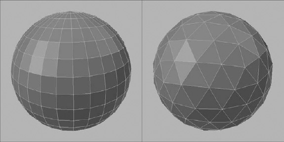
In the case of this specific eye model that you're creating, it's most prudent to take a box modeler's approach, though, with a primitive that more closely matches the base shape you need. That means you're going to use a sphere. If you go to add a new mesh object in the 3D View (Shift+A![]() Mesh), you might notice that Blender ships with two different sphere primitives: UV sphere and icosphere. Figure 5-18 shows these two types of spheres in Edit mode so that you can see the differences between them.
Mesh), you might notice that Blender ships with two different sphere primitives: UV sphere and icosphere. Figure 5-18 shows these two types of spheres in Edit mode so that you can see the differences between them.
The primary difference between the UV sphere and the icosphere is topology. The UV sphere is made up predominantly of quads, whereas the icosphere is composed entirely of equilateral triangles. In the case of this model, you can take advantage of the radial topology at the top and bottom of the UV sphere primitive to more easily form some of the eye's features. For that reason, the UV sphere is what you want to add (Shift+A![]() Mesh
Mesh![]() UV Sphere).
UV Sphere).
![]() After adding the sphere, notice that the Last Operation panel at the bottom of the Tool Shelf updates to show Add UV Sphere and provides some settings for you to adjust. You can use these values to tweak your initial base mesh. In this case, the default values work just fine, but you're welcome to play with these settings. If you hid the Tool Shelf (T), you can quickly pull up these settings after adding your sphere by pressing F6 in the 3D View.
After adding the sphere, notice that the Last Operation panel at the bottom of the Tool Shelf updates to show Add UV Sphere and provides some settings for you to adjust. You can use these values to tweak your initial base mesh. In this case, the default values work just fine, but you're welcome to play with these settings. If you hid the Tool Shelf (T), you can quickly pull up these settings after adding your sphere by pressing F6 in the 3D View.
Figure 5-18: The UV sphere (left) features topology like a globe, while the icosphere (right) is built from a set of equilateral triangles.
After you add your UV sphere, tab into Edit mode and rotate the vertices of your sphere by 90 degrees about the X-axis. If you like using the 3D manipulator, switch it to rotate by clicking its icon in the 3D View's header. Then you can click the red X-axis control and rotate by 90 degrees. Remember that you can see how much you're rotating by in the bottom-left corner of the 3D View's header. Also, hold Ctrl as you're rotating so that you can rotate in exact fixed increments. Of course, the fastest way to do this rotation operation is with the following hotkey sequence: R![]() X
X![]() 90
90![]() Enter.
Enter.
Creating the pupil and iris
After you rotate your UV sphere, you can form the basic structure of the eye. This process starts with forming the pupil and iris area. Use the following steps:
- Select the pole vertex at the front of your UV sphere.
It may be helpful to do this step from the front (Numpad 1) or right side view (Numpad 3) to make selection easier.
- Enable the Proportional Edit Tool (O).
This step allows adjustments to your selected vertex to influence some of the vertices near it.
- Grab your pole vertex and move it along the Y-axis toward the center of your sphere (G
 Y).
Y).
While moving this vertex, use the scroll wheel on your mouse or the Page Up and Page Down buttons on your keyboard to adjust the influence of the Proportional Edit Tool. The area of influence should include the first two concentric edge loops around your pole vertex.
With those steps completed, you have the basic structure for your eye model. The reason for building the iris and pupil this way is a bit of a lighting trick. Because of the lens in the eye, the iris appears to reflect light in a pretty unique way. By pulling that pole vertex and the edge loops surrounding it slightly inward, you provide a surface for the light to reflect off of. Figure 5-19 shows what your eye model should look like at this point.
Technically, if you're working on a low polygon model, you could probably just stop here. However, assume that you want to add a bit more detail to your eye. You may be tempted to just add a Subdivision Surface modifier and be done with it, but try a slightly more sophisticated approach. In order to take that approach, you need a little more geometry on your mesh. In particular, you need to add detail in the pupil and iris areas. To do so, you need to add some more edge loops. Start with the easy loops in the iris.
![]() A good general rule when you model is that you should try to keep the faces in your mesh roughly square and roughly all the same size.
A good general rule when you model is that you should try to keep the faces in your mesh roughly square and roughly all the same size.
If you look at the iris of your model, those faces are stretched and rectangular. You can make the faces more proportional by adding an edge loop along the middle of them. You start this process by clicking the Loop Cut and Slide button on the Tool Shelf or pressing Ctrl+R. Then run your mouse cursor over your mesh until the pink preview loop shows the loop you want to create at the midpoint of the edge loops that define the iris. Left-click to confirm the loop cut and either slide the loop into place manually or simply right-click, and Blender automatically places the edge loop at that midpoint.
Figure 5-19: Your basic eye model.

Taking a knife to your pupil
Now you need to create some edge loops to more clearly define the pupil. However, one loop you should add is in the cone that forms the pupil. Edge loops terminate at poles that don't connect exactly four edges. For this reason, the Loop Cut and Slide feature (Ctrl+R) can't create a new edge loop in the cone. Instead, you need to use the Knife tool. Something to remember about the Knife tool is that it operates only on selected edges and faces, so you first need to select the faces you're interested in. A quick way to do make that selection is using this handy two-step process:
- Select the pole vertex at the center of your pupil.
In solid viewport shading, that vertex is sometimes hard to select. You may have to quickly switch to wireframe viewport shading (Z).
- Increase your selection by pressing Ctrl+Numpad Plus (+).
Neat, huh? Now you can go ahead and use the Knife tool. You may find it easiest to do these next steps after toggling wireframe viewport shading (Z) and switching to the right side view (Numpad 3).
- With your desired faces selected, use the Knife tool to cut a new loop.
Hold down K and then left-click and drag your mouse to draw a line where you want to cut. When you release your mouse button and K, anywhere your line crossed an edge, a new vertex is created. This Exact type of cut is the Knife tool's default behavior. Of course, exact cuts are ugly looking, so use the next step to fix that problem.
- Using the Last Operation panel in the Tool Shelf or the F6 pop-up panel, change the cut Type from Exact to Midpoints.
Your newly created edge loop cleans up immediately. What you're going to do now is use your new edge loop to form the base of the pupil.
- Grab the edge loop and move it along the Y-axis toward the pole vertex at the center of the pupil (GY).
After the pupil is more clearly defined, you again have rectangular faces in your mesh, this time leading from the interior iris edge loop back to your new edge loop. It's not super critical that you deal with these faces, but taking care of them isn't a bad idea.
- Add a new edge loop along the faces that define the pupil.
From this point, you can tweak to taste. The next steps are optional, but they're something I like to do.
- (Optional) Select the innermost edge loop of the iris (Alt+right-click).
- (Optional) Enable Proportional Editing (O).
- (Optional) Scale (S) the edge loop down to make the pupil area a bit more cylindrical.
Use your mouse's scroll wheel to adjust the influence of the Proportional Edit Tool to taste.
- Disable Proportional Editing (O).
At this point, the detailed eye is nearly done. It should look something like the image in Figure 5-20.
Figure 5-20: A more detailed eye model.

Smoothing out the eye interior
Now it's time for some polish. Up to this point, you've been working with a faceted, flat-shaded model. The next step is to smooth things out a bit:
- Select all vertices in your mesh (AA).
- Set the shading type on the selected faces to Smooth.
Simply click Shading
Smooth in the Tool Shelf or press WShade Smooth. You're off to a good start, but assume that you're working with a model that allows for a high polygon count. The facets on your eye model are still somewhat noticeable. The next step can help. - Add the Subdivision Surface modifier.
You can add this modifier in Modifiers Properties or quickly tab out to Object mode, use the Ctrl+1 hotkey, and tab back into Edit mode.
This smoother eye looks pretty nice, but the iris has lost a bit of its definition. Fortunately, you can easily add definition with just a little bit more geometry, two edge loops to be exact. You add one near the outer edge of the iris and another near the inner edge. Uses the same process as when adding an edge loop along the center of the iris: Loop Cut and Slide (Ctrl+R) where you want the new loop, left-click to confirm and create the loop, move your mouse cursor to slide the edge into place, and left-click again to confirm its location. When you're done, you should have an eye model like the one in Figure 5-21.
Building the eye's exterior
At this point, the hard part is done. All that remains is creating the exterior shell of the eye. Medically speaking, the shell would be the cornea and the sclera. For this model, form them as a single mesh. Now, the temptation here is simply to create a new UV sphere and make it slightly bigger than your eye model — and this approach actually would work fine. However, the downside of this technique is that it puts a pole right at the center of the eye, and the triangles caused by that pole can sometimes cause some ugly artifacts when you try to render your model. Fortunately, you can create this shell using a subdivided cube and Blender's handy To Sphere operator:
- Tab into Object mode, if you haven't already.
- Add a new Cube mesh (Shift+AMeshCube).
- Tab into Edit mode on your new cube mesh.
- Smoothly subdivide the cube (WSubdivide Smooth).
- In the Last Operator panel, change the Number of Cuts value to 6.
- Use the To Sphere operator and make the cube fully sphere-shaped (Shift+Alt+S1Enter).
- Set shading to smooth (WShade Smooth).
- Add a Subdivision Surface modifier (TabCtrl+1Tab).
You've just turned a cube into a sphere! It should look something like the image in Figure 5-22.
Now you just have to get that sphere to fit the eye you've already modeled and make a bulge for the cornea. You can easily do so with the following steps.
- Scale (S) your spherized cube down to fit the size of your eye model.
I find that the best method is with the viewport in wireframe (Z) and from the front view (Numpad 1). You may also want to hold down Shift while scaling so that you have more refined control.
- Switch to Face Select mode (Ctrl+TabFace) and select the polygon at the center front of your mesh, right in front of the pupil.
This face is what you're going to use to create the bulge for the cornea.
- Enable Proportional Editing (O), grab the selected face (G), and move it along the Y-axis, away from the center of the eye.
Use your mouse's scroll wheel to adjust the influence of the Proportional Edit Tool. It may be useful to work from the right side view (Numpad 3) as a wireframe (Z). You may also want to look on the Web for an illustrated reference of how far this bulge sticks out. I've exaggerated the cornea a little for this example so that it's visible in figures.
- Disable Proportional Editing (O).
At this point, the model for your eye is essentially done. Clean things up a bit by selecting both of the meshes you created and joining them (Ctrl+J) as a single object. Also, go to the Object Properties and name your model something logical, like eye. Figure 5-23 shows what your final model should look like.
You have an eyeball!! Save this model because you can use it again for the materials and texturing example in Chapter 7.
Figure 5-21: Your eye model, all smooth and nice looking.

Figure 5-22: It used to be a cube, and now it's a sphere!

