
Chapter 14. The imaging model
- The PDF imaging model
- All methods in PdfContentByte
- Using Graphics2D to create PDF content
We studied the Carousel Object System in the previous chapter. We used iText to find, remove, change, and replace objects in a PDF file. In this chapter, we’ll look at one specific type of object: the stream containing the syntax that makes up a page.
First we’ll look at the PDF imaging model and learn how to draw graphics and text using PDF syntax. Then we’ll look at the Java class java.awt.Graphics2D as an alternative solution for achieving the same results. In both cases, we’ll add content at absolute positions as we did in chapter 3. Chapter 3 explained the mechanisms available in iText, but this chapter dives straight into the PDF syntax.
This chapter includes different tables listing all the possible graphics and text operators and operands. This chapter will serve as a reference that can be used to look up the meaning of the syntax in a PDF file, and to find the iText methods that correspond with this syntax.
14.1. Examining the content stream
Let’s start by looking at the content streams of some PDF samples you’ve created in previous parts of the book. A first step is to get the content of a page.
Listing 14.1. GetContentStream.java
public void readContent(String src, String result) throws IOException {
  PdfReader reader = new PdfReader(src);
  FileOutputStream out = new FileOutputStream(result);
  out.write(reader.getPageContent(1));
  out.flush();
  out.close();
}
If you try this example on your Hello World example from chapter 1, you’ll get this stream:
q
BT
36 806 Td
0 -18 Td
/F1 12 Tf
(Hello World!)Tj
0 0 Td
ET
Q
This stream contains mainly text operators, and using the tables in section 14.4, you’ll be able to interpret every character in this stream. If you execute the code in listing 14.1 on the first superhero example in chapter 5, you’ll get the following stream:
q
BT
-1156 1649 Td
ET
Q
q 1 0 0 1 -1192 -1685 cm /Xf1 Do Q
-595 0 m
595 0 l
0 -842 m
0 842 l
S
This stream contains mainly graphics operators, but the syntax that draws Superman is missing. We’ll look into where to find it, and we’ll discuss these operators, in sections 14.2 and 14.3.
PDF Syntax Notation
PDF (and PS) use a notation known as postfix, aka reverse Polish notation. In reverse Polish notation, the operators follow their operands. Table 14.1 shows the different notations that can be used to note down the addition of the integers 10 and 6.
Table 14.1. Mathematical notations
|
Example |
Description |
|
|---|---|---|
| Prefix | + 10 6 | Polish notation |
| Infix | 10 + 6 | The common arithmetic and logical formula notation |
| Postfix | 10 6 + | Reverse Polish notation |
Interpreters of the postfix notation are often stack-based. Operands are pushed onto a stack, and when an operation is performed, its operands are popped from a stack and its result pushed back on. This has the advantage of being easy to implement and very fast.
When you look at the content stream snippets extracted from a PDF file using listing 14.1, you’ll see operations such as -595 0 m, where -595 and 0 are the operands (in this case, representing a translation), and where m is the operator (which will cause the cursor to move 595 points to the left and 0 points up).
In iText, this syntax is generated by the PdfContentByte class. This class was introduced in section 3.1, where you used it to draw paths and text at absolute positions—to create a movie calendar, for instance. One of the member variables of this object is a ByteBuffer, storing the PDF syntax until it can be put into a stream object. This stream can be added to a PDF file as the content of a page, as a form XObject, or as the appearance of an annotation.
This chapter contains a series of tables listing graphics and text operators in PDF, along with the corresponding methods in the PdfContentByte class.
14.2. Path construction and painting operators
The first series of operators we’ll look at can be used to construct paths that will be used to stroke lines and to fill shapes.
14.2.1. Constructing paths
Figure 14.1 shows a series of paths that are constructed using PdfContentByte methods.
Figure 14.1. Constructing and painting paths

These methods and the corresponding PDF operators are listed in table 14.2.
Table 14.2. PDF path construction operators and operands
|
|
iText method |
Parameters |
Description |
|---|---|---|---|
| m | moveTo | (x, y) | Moves the current point to coordinates (x,y), omitting any connecting line segment. This begins a new (sub) path. |
| l | lineTo | (x, y) | Moves the current point to coordinates (x,y), appending a line segment from the previous to the new current point. |
| c | curveTo | (x1, y1, x2, y2, x3, y3) | Moves the current point to coordinates (x3,y3), appending a cubic Bézier curve from the previous to the new current point, using (x1,y1) and (x2,y2) as Bézier control points. |
| v | curveTo | (x2, y2, x3, y3) | Moves the current point to coordinates (x3, y3), appending a cubic Bézier curve from the previous to the new current point, using the previous current point and (x2,y2) as Bézier control points. |
| y | curveFromTo | (x1, y1, x3, y3) | Moves the current point to coordinates (x3,y3), appending a cubic Bézier curve from the previous to the new current point, using (x1,y1) and (x3,y3) as Bézier control points. |
| h | closePath | () | Closes the current subpath by appending a straight line segment from the current point to the starting point of the subpath. |
| re | rectangle | (x, y, width, height) | Appends a rectangle to the current path as a complete subpath. (x,y) is the lower-left corner; width and height define the dimensions of the rectangle. |
You can move the cursor to specific coordinates using moveTo(). Straight lines are constructed with the lineTo() method. The first series of paths shown in figure 14.1 are drawn using one moveTo() and three lineTo() operations. The first path is an open shape because I didn’t “close the path” as was done for the second path.
Curves are constructed using the curveTo() or curveFromTo() methods. The curve segments added to the path are Bézier curves.
Bézier Curves
Bézier curves are parametric curves developed in 1959 by Paul de Casteljau (using de Casteljau’s algorithm). They were widely publicized in 1962 by Paul Bézier, who used them to design automobile bodies. Nowadays they’re important in computer graphics.
Cubic Bézier curves are defined by four points: the two endpoints—the current point and point (x3,y3)—and two control points—(x1,y1) and (x2,y2). The curve starts at the first endpoint going onward to the first control point, and it arrives at the second endpoint coming from the second control point. In general, the curve doesn’t pass through the control points. They’re there only to provide directional information. The distance between an endpoint and its corresponding control point determines how long the curve moves toward the control point before turning toward the other endpoint.
The Bézier curves shown in figure 14.1 demonstrate the different curve methods from table 14.2. The extra straight lines connect the endpoints with the corresponding control points. In the second example, the endpoint to the left coincides with the first control point (the PDF operator v is used instead of c). In the third example, the endpoint to the right coincides with the second control point (the PDF operator y was used).
14.2.2. Painting and clipping paths
The methods listed in table 14.2 can be used to construct a path, using different straight and curved segments, but these methods won’t draw any line or shape on the page.
FAQ
I’ve used methods such as moveTo(), lineTo(), and curveTo() to draw a shape, but this shape doesn’t show up on my page. This is normal; you have been constructing a path using different subpaths, but this path wasn’t drawn because you forgot to stroke or fill the line or shape. Not all shapes are meant to be drawn—a shape can also be used to clip content.
Table 14.3 lists the different path-painting and -clipping operators. Note that they don’t have any operands.
Table 14.3. PDF path-painting and -clipping operators
|
|
iText method |
Description |
|---|---|---|
| S | stroke() | Strokes the path (lines only; the shape isn’t filled). |
| s | closePathStroke() | Closes and strokes the path. This is the same as doing closePath() followed by stroke(). |
| f | fill() | Fills the path using the nonzero winding number rule. Open subpaths are closed implicitly. |
| F | - | Deprecated! Equivalent to f, and included for compatibility. ISO-32000-1 says that PDF writer applications should use f instead. |
| f* | eoFill() | Fills the path using the even-odd rule. |
| B | fillStroke() | Fills the path using the nonzero winding number rule, and then strokes the path. This is equivalent to fill() followed by stroke(). |
| B* | eoFillStroke() | Fills the path using the even-odd rule, and then strokes the path. This is equivalent to eoFill() followed by stroke(). |
| b | closePathFillStroke() | Closes, fills, and strokes the path, as is done with closePath() followed by fillStroke(). |
| b* | closePathEoFillStroke() | Closes, fills, and strokes the path, as is done with closePath() followed by eoFillStroke(). |
| n | newPath() | Ends the path object without filling or stroking it. Used primarily after defining a clipping path. |
| W | clip() | Modifies the current clipping path by intersecting it with the current path, using the nonzero winding rule. |
| W* | eoClip() | Modifies the current clipping path by intersecting it with the current path, using the even-odd rule. |
When you construct a path using the methods from table 14.2, you can stroke those paths. Stroking a path means you’re going to draw the line segments of the subpaths. The color used by default is black, but you can change this color with one of the setColorStroke() methods in table 14.8.
Filling a path means you’re going to paint the entire region enclosed by the path. By default, shapes are filled using the nonzero winding number rule.
Nonzero Winding Number Rule Versus Even-Odd Rule
When I close my eyes, I can still see how our professor of analytic geometry filled two of his nine blackboards explaining how to determine whether or not a given point is inside a path.
With the nonzero winding number rule, you need to draw a line from that point in any direction, and examine every intersection of the path with this line. Start with a count of zero; add one each time a subpath crosses the line from left to right; subtract one each time a subpath crosses from right to left. Do this until there are no more path segments to cross. If the result is zero, the point is outside the path; otherwise, it’s inside.
An alternative to the nonzero winding number rule is the even-odd rule. Again, you need to draw a line from the point that’s being examined to infinity. Now count the number of path segments that are crossed, regardless of the direction. If this number is odd, the point is inside; if even, the point is outside.
If you don’t like to read definitions, have a look at the stars and circles in figure 14.2.
Figure 14.2. Constructing and painting shapes

The paths of the star and circle shapes are constructed using listing 14.2. Observe that the star is composed of five straight lines, four of which are created using the lineTo() method and one implicitly using closePath().
Listing 14.2. PathConstructionAndPainting.java
public static void createStar(PdfContentByte canvas, float x, float y) {
  canvas.moveTo(x + 10, y);
  canvas.lineTo(x + 80, y + 60);
  canvas.lineTo(x, y + 60);
  canvas.lineTo(x + 70, y);
  canvas.lineTo(x + 40, y + 90);
  canvas.closePath();
}
public static void createCircle(PdfContentByte canvas, float x, float y,
  float r, boolean clockwise) {
  float b = 0.5523f;
  if (clockwise) {
    canvas.moveTo(x + r, y);
    canvas.curveTo(x + r, y - r * b, x + r * b, y - r, x, y - r);
    canvas.curveTo(x - r * b, y - r, x - r, y - r * b, x - r, y);
    canvas.curveTo(x - r, y + r * b, x - r * b, y + r, x, y + r);
    canvas.curveTo(x + r * b, y + r, x + r, y + r * b, x + r, y);
  } else {
    canvas.moveTo(x + r, y);
    canvas.curveTo(x + r, y + r * b, x + r * b, y + r, x, y + r);
    canvas.curveTo(x - r * b, y + r, x - r, y + r * b, x - r, y);
    canvas.curveTo(x - r, y - r * b, x - r * b, y - r, x, y - r);
    canvas.curveTo(x + r * b, y - r, x + r, y - r * b, x + r, y);
  }
}
The circle is constructed using four Bézier curves. With the method createCircle(), you can construct the path clockwise and counterclockwise.
Now look at the next listing to see how the shapes in figure 14.2 were added.
Listing 14.3. PathConstructionAndPainting.java (continued)

The paths for the stars and circles are filled in different ways. The first pair is filled using the nonzero winding number
rule ![]() . The inner circle overlaps the outer circle, but it has the same color; you can’t distinguish the inner circle from the outer
one.
. The inner circle overlaps the outer circle, but it has the same color; you can’t distinguish the inner circle from the outer
one.
In the second pair, the star and the circle are filled using the even-odd rule ![]() . The middle part of the star isn’t filled, nor is the inner circle.
. The middle part of the star isn’t filled, nor is the inner circle.
The star seems to be missing in the third example. This time the newPath() method is used ![]() , and it has discarded the subpaths that were on the stack. Only the circles are drawn. They’re filled and stroked using the
nonzero winding number rule
, and it has discarded the subpaths that were on the stack. Only the circles are drawn. They’re filled and stroked using the
nonzero winding number rule ![]() .
.
Note the difference between the third and the fourth concentric circles. In the third column, the subpaths of the circles are constructed clockwise—the curves are drawn in that direction. In the fourth column, the path of the outer circle is constructed clockwise, and the path of the inner circle is constructed counterclockwise.
By definition, the direction of the paths doesn’t matter when filling the circles using the even-odd rule, as is the case
in the fifth pair of circles ![]() .
.
Computing the values to draw Bézier curves representing a simple circle or an ellipse isn’t easy. That’s why iText provides convenience methods.
14.2.3. Convenience methods to draw shapes
Table 14.4 lists the convenience methods that were used to draw the final row of shapes shown in figure 14.2. These shapes can’t be drawn using a single operator in PDF. The path is constructed using different subpaths as was done for the circle in listing 14.2.
Table 14.4. iText convenience methods for graphics
|
iText method |
Parameters |
Description |
|---|---|---|
| arc | (x1, y1, x2, y2, startAng, extent) | Constructs the path of a partial ellipse inscribed within the rectangle [x1 y1 x2 y2], starting at startAng degrees and covering extent degrees. Angles start with 0 to the right and increase counterclockwise. |
| ellipse | (x1, y1, x2, y2) | Constructs the path of an ellipse using the arc method, starting at 0 degrees and covering 360 degrees. |
| circle | (x, y, r) | Constructs the path of a circle with center (x,y) and radius r using one moveTo() and four curveTo() instructions. |
| roundRectangle | (x, y, w, h, r) | Constructs the path of a rounded rectangle. |
| rectangle | (rect) | Draws a Rectangle object. Constructs the path, fills it with the background color of rect (if any) and strokes the borders. |
The first four methods in this table construct the path, but don’t draw it; this is similar to what the rectangle() method in table 14.2 does. If you want to see the shapes, you need to stroke() or fill() the paths, or both. The rectangle() method in table 14.4 calls these methods implicitly, because there are different colors and line widths involved.
To draw lines and shapes using different stroke and fill properties, you’ll need to change the graphics state.
14.3. Overview of the graphics state methods
The mechanism of the graphics state stack was explained in section 3.1.2, but we didn’t get a complete overview of all the methods that were available. Table 14.5 lists a series of graphics state operators.
Table 14.5. Graphics state operators
|
|
iText method |
Parameters |
Description |
|---|---|---|---|
| w | setLineWidth | (width) | Sets the line width. The parameter represents the thickness of the line in user units (default = 1). |
| J | setLineCap | (style) | Defines the line cap style. |
| j | setLineJoin | (style) | Defines the line join style. |
| M | setMiterLimit | (miterLimit) | Defines a limit for joining lines. When it’s exceeded, the join is converted from a miter to a bevel. |
| d | setLineDash | (phase) (unitsOn, phase) (unitsOn, unitsOff, phase) (array, phase) | Sets the line dash type. The default line dash is a solid line, but by using the different iText methods that change the dash pattern, you can create all sorts of dashed lines. |
| i | setFlatness | (flatness) | Sets the maximum permitted distance, in device pixels, between the mathematically correct path and an approximation constructed from straight line segments. This is a value between 0 and 100. Smaller values yield greater precision at the cost of more computation. |
| q | saveState | () | Saves the current graphics state on the graphics state stack. |
| Q | restorestate | () | Restores the graphics state by removing the most recently saved state from the stack, making it the current stack. |
| gs | setGState | (gstate) | Sets a group of parameters in the graphics state using a graphics state parameter dictionary. |
| /RI | PdfGState.setRenderingIntent | (name) | Sets the color rendering intent in the graphics state.Possible values are /AbsoluteColorimetric, /RelativeColorimetric, /Saturation, and /Perceptual. |
| cm | concatCTM | (a, b, c, d, e, f) | Modifies the current transformation matrix (CTM) by concatenating the matrix defined by the parameters a, b, c, d, e, and f. |
Let’s work through some examples involving lines and their characteristics, and take a closer look at the different parameters that can be used for the methods that change the graphics state for stroking lines.
14.3.1. Line characteristics
Figure 14.3 shows some of the characteristics that can be defined for lines.
Figure 14.3. Examples of different line characteristics

This listing demonstrates how all but the dashed lines in figure 14.3 were drawn.
Listing 14.4. GraphicsStateOperators.java

In this code sample, you first draw a series of lines with widths varying from 0.1 pt to 2.5 pt. See the lines on the top-left of figure 14.3.
Note
It’s important to understand that not all devices are able to render lines with the widths you specify in your PDF. The actual line width can differ from the requested width by as much as 2 device pixels, depending on the positions of the lines with respect to the pixel grid. When drawing lines and shapes, the flatness tolerance (i in table 14.5) controls the maximum permitted distance in device pixels between the mathematically correct path and an approximation constructed from straight line segments.
The three thick lines at the top right in figure 14.3 are drawn from x = 350 to x = 540, but they appear to have different lengths. That’s because they’re drawn using different line cap styles. The line cap styles are listed in table 14.6.
Table 14.6. Line cap styles
|
Style |
Description |
|---|---|
| LINE_CAP_BUTT | The stroke is squared off at the endpoint of the path. This is the default. |
| LINE_CAP_ROUND | A semicircular arc with diameter equal to the line width is drawn around the endpoint. |
| LINE_CAP_PROJECTING_SQUARE | The stroke continues beyond the endpoint of the path for a distance equal to half the line width. |
The three hook shapes under these thick lines demonstrate the different line join styles shown in table 14.7.
Table 14.7. Line join styles
|
Style |
Description |
|---|---|
| LINE_JOIN_MITER | The outer edges of the strokes for two segments are extended until they meet at an angle. This is the default. |
| LINE_JOIN_ROUND | An arc of a circle with diameter equal to the line width is drawn around the point where the two line segments meet. |
| LINE_JOIN_BEVEL | The two segments are finished with butt caps. |
When you define miter joins, and two line segments meet at a sharp angle, it’s possible for the miter to extend far beyond the thickness of the line stroke. If φ is the angle between both line segments, the miter limit equals the line width divided by sin(φ/2).
You can define a maximum value for the ratio of the miter length to the line width. This maximum is called the miter limit. When this limit is exceeded, the join is converted from a miter to a bevel. Figure 14.3 shows two rows of hooks that were drawn using the same PdfTemplate object hooks. The angle of the hooks decreases from left to right. In spite of the fact that the PDF syntax to draw the hooks is identical, the appearance of the third hook is different when comparing both lines because of the different miter limit:
canvas.saveState();
canvas.setMiterLimit(2);
canvas.addTemplate(hooks, 300, 600);
canvas.restoreState();
canvas.saveState();
canvas.setMiterLimit(2.1f);
canvas.addTemplate(hooks, 300, 550);
canvas.restoreState();
Figure 14.3 also demonstrates how you can create dashed lines. The next listing shows how these lines were created.
Listing 14.5. GraphicsStateOperators.java

The first line is drawn using the default line style, which is solid ![]() . For the second line, the line dash is set to a pattern of 6 units with phase 0
. For the second line, the line dash is set to a pattern of 6 units with phase 0 ![]() . This means that the line starts with a dash of 6 units long, then there’s a gap of 6 units, and then there’s a dash of 6
units, and so on. The same goes for the third line, but it uses a different phase
. This means that the line starts with a dash of 6 units long, then there’s a gap of 6 units, and then there’s a dash of 6
units, and so on. The same goes for the third line, but it uses a different phase ![]() . In line
. In line ![]() , you have a dash of 15 units and a gap of 10 units. The phase is 5, so the first dash is only 10 units long (15 – 5). Line
, you have a dash of 15 units and a gap of 10 units. The phase is 5, so the first dash is only 10 units long (15 – 5). Line
![]() uses a more complex pattern. You start with a dash of 5 (10 – 5), then there’s a gap of 5, followed by a dash of 5, a gap
of 5, and a dash of 20. The next sequence is as follows: a gap of 10, a dash of 5, a gap of 5, a dash of 5, a gap of 20, and
so on. Situation
uses a more complex pattern. You start with a dash of 5 (10 – 5), then there’s a gap of 5, followed by a dash of 5, a gap
of 5, and a dash of 20. The next sequence is as follows: a gap of 10, a dash of 5, a gap of 5, a dash of 5, a gap of 20, and
so on. Situation ![]() is also special: a dash of 9, a gap of 6, a dash of 0, and a gap of 6. The dash of 0 may seem odd, but as you’re using round
caps, a dot is drawn instead of a 0-length dash.
is also special: a dash of 9, a gap of 6, a dash of 0, and a gap of 6. The dash of 0 may seem odd, but as you’re using round
caps, a dot is drawn instead of a 0-length dash.
Most of these characteristics can also be set outside the content stream, in a reusable graphics state parameter dictionary.
Graphics State Parameter Dictionary
The graphics state stack is initialized at the beginning of each page using the default value for every graphics state parameter. You can change the state with the operators described in this chapter, and then save and restore the state with saveState() and restoreState(). If you want to reuse a set of parameters, you can store them in an external dictionary with /Type /ExtGState, and refer to that dictionary with the setGState() method.
In such a dictionary, the key /LW is used for the line width parameter, /LC for the line cap, /LJ for the line join, /ML for the miter limit, /D for the dash pattern, and so on. For the complete list, see table 58 in ISO-32000-1.
One of the operators in that table also appears in our table 14.5; with /RI, you can set the color rendering intent by using a method in the PdfGState class. You used this class earlier, when we discussed transparency and colors in chapter 10.
14.3.2. Colors
You can change the color of the current graphics state using the methods setColorStroke() and setColorFill(). These methods accept an instance of the BaseColor class. This class has many different subclasses, and the type of the subclass will determine which operator is used. Table 14.8 lists the different operators and operands that are at play.
Table 14.8. Color and shading methods
|
|
iText method |
Parameters |
Description |
|---|---|---|---|
| g | setGrayFill | (gray) | Changes the current gray tint for filling paths to a float value from 0 (black) to 1 (white), |
| G | setGrayStroke | (gray) | Changes the current gray tint for stroking paths to a float value from 0 (black) to 1 (white). |
| rg | setRGBColorFill | (red, green, blue) | Sets the color space to DeviceRGB and changes the current color for filling paths. The color values are integers from 0 to 255. |
| RG | setRGBColorStroke | (gray) | Sets the color space to DeviceRGB and changes the current color for stroking paths. The color values are integers from 0 to 255. |
| rg | setRGBColorFillF | (red, green, blue) | Sets the color space to DeviceRGB and changes the current color for filling paths. The color values are floats from 0 to 1. |
| RG | setRGBColorStrokeF | (gray) | Sets the color space to DeviceRGB and changes the current color for stroking paths. The color values are floats from 0 to 1. |
| k | setCMYKColorFill | (cyan, magenta, yellow, black) | Sets the color space to DeviceCMYK and changes the current color for filling paths. The color values are integers from 0 to 255. |
| K | setCMYKColorStroke | (cyan, magenta, yellow, black) | Sets the color space to DeviceCMYK and changes the current color for stroking paths. The color values are integers from 0 to 255. |
| k | setCMYKColorFillF | (cyan, magenta, yellow, black) | Sets the color space to DeviceCMYK and changes the current color for filling paths. The color values are floats from 0 to 1. |
| K | setCMYKColorStrokeF | (cyan, magenta, yellow, black) | Sets the color space to DeviceCMYK and changes the current color for stroking paths. The color values are floats from 0 to 1. |
| CS | name | Sets the color space for nonstroking operations. This is done implicitly when necessary by iText. | |
| cs | name | Sets the color space for nonstroking operations. This is done implicitly when necessary by iText. | |
| SC | c1 c2 c3 ... | Sets the color to use for stroking operations in a device, CIEbased (other than ICCBased), or Indexed color space. Not used in iText. | |
| sc | c1 c2 c3 ... | Same as SC for nonstroking operations. Not used in iText. | |
| SCN | c1 c2 c3 ... name | Same as SC but also supports Pattern, Separation, DeviceN, and ICCBased color spaces. It’s used in the methods setColorStroke(PdfSpotColor sp, float tint), setPatternStroke(PdfPatternPainter p), setPatternStroke(PdfPatternPainter p, BaseColor color), setPatternStroke(PdfPatternPainter p, BaseColor color, float tint), and setShadingStroke(PdfShadingPattern shading). | |
| scn | c1 c2 c3 ... name | Same as SC but also supports Pattern, Separation, DeviceN, and ICCBased color spaces. It’s used in the methods setColorFill(PdfSpotColor sp, float tint), setPatternFill(PdfPatternPainter p), setPatternFill(PdfPatternPainter p, BaseColor color), setPatternFill(PdfPatternPainter p, BaseColor color, float tint), and setShadingFill(PdfShadingPattern shading). | |
| sh | paintShading | (shading) | Paints the shape and color shading described by a shading dictionary. In iText the shading dictionary can be a PdfShading or PdfShadingPattern object. |
Before we move on to the text operators, we need to discuss one more mechanism in more detail: the coordinate system that’s used in PDF.
14.3.3. Changing the coordinate system
In chapter 3, you learned that the origin of the coordinate system can usually be found in the lower-left corner of the page. For an A4 page in portrait orientation, the upper-right corner has the coordinates (595,842). We amended this in chapter 5, where you created a superhero PDF with page size A0 with the origin of the coordinate system centered in the middle of the page.
Figure 14.4 is similar. The origin of the coordinate system is marked by two lines, where Y = 0 (the X axis) and X = 0 (the Y axis).
Figure 14.4. The current transformation matrix

To this page, the same logo was added six times using the method addTemplate (template, 0, 0). However, the template is added at a different places and the shape changes. It looks translated, scaled, skewed, and rotated because the current transformation matrix is changed. This shows how it is done.
Listing 14.6. TransformationMatrix1.java

The six values of the concatCTM() method are elements of a matrix that has three rows and three columns:

You can use this matrix to express a transformation in a two-dimensional system:

Carrying out this multiplication results in this:
x' = a * x + c * y + e
y' = b * x + d * y + f
The third column in the matrix is fixed: you’re working in two dimensions, so you don’t need to calculate a new z coordinate.
There’s one big difference here from what you were taught at school; in most math books you can read about transforming objects (points, lines, shapes), rather than coordinate systems. This demands a slightly different point of view.
To understand the mathematics of coordinate transformations in PDF, it’s vital to remember what is written in ISO-32000-1 (section 8.3.4):
All objects painted before a transformation is applied shall be unaffected by the transformation. Objects painted after the transformation is applied, shall be interpreted in the transformed coordinate system.
Transformation matrices specify the transformation from the new (transformed) coordinate system to the original (untransformed) coordinate system. All coordinates used after the transformation shall be expressed in the transformed coordinate system.
Translating the coordinate system in direction (dX, dY) is done like this:
x' = 1 * x + 0 * y + dX
y' = 0 * x + 1 * y + dY
These formulas scale the coordinate system with factors sX in the X direction and sY in the Y direction:
x' = sX * x + 0 * y + 0
y' = 0 * x + sY * y + 0
To rotate the coordinate system with an angle φ, you need to use the following equations:
x' = cos(φ) * x - sin(φ) * y + 0
y' = sin(φ) * x + cos(φ) * y + 0
Skewing the coordinates is done like this:
x' = 1 * x + tan(β) * y + 0
y' = tan(α) * x + 1 * y + 0
where α is the new angle of the X axis and β is the new angle of the Y axis.
You can use these formulas to compute the values for a, b, c, d, e, and f. For example, if you want to combine a translation (dX, dY), a scaling (sX, sY), and a rotation φ, you’d use these values:
a = sX * cos(φ);
b = sY * sin(φ);
c = sX * -sin(φ);
d = sY * cos(φ);
e = dX;
f = dY;
If you combine different concatCTM() operations, you can compute the resulting transformation by multiplying the matrices with each other.
Note
The order is important when performing transformations one after the other. This can be demonstrated by switching the lines with concatCTM() methods in the sequence between saveState() and restoreState() in listing 14.6.
Suppose you want the same result as shown in figure 14.4 but without using concatCTM() directly. In that case, you’ll need a version of the addTemplate() method that takes a, b, c, d, e, and f parameters.
Adding Templates and Images
Listing 14.7 is exactly equivalent to listing 14.6. First you add the template without any transformation ![]() in listing 14.7. Then you add two templates,
in listing 14.7. Then you add two templates, ![]() and
and ![]() , which are scaled and translated:
, which are scaled and translated: ![]() skews and translates the template, and
skews and translates the template, and ![]() rotates and translates the template. Finally, the template is rotated, scaled, and translated
rotates and translates the template. Finally, the template is rotated, scaled, and translated ![]() .
.
Listing 14.7. TransformationMatrix2.java
canvas.addTemplate(template, 0, 0);
canvas.addTemplate(template, 0.5f, 0, 0, 0.5f, -595, 0);
canvas.addTemplate(template, 0.5f, 0, 0, 0.5f, -297.5f, 297.5f);
canvas.addTemplate(template, 1, 0, 0.4f, 1, -750, -650);
canvas.addTemplate(template, 0, -1, -1, 0, 650, 0);
canvas.addTemplate(template, 0, -0.2f, -0.5f, 0, 350, 0);
The transformation matrix elements in ![]() are the result of the following multiplication:
are the result of the following multiplication:

The parameters in ![]() were computed like this:
were computed like this:

Observe that you get a different result if you switch the order of the multiplication:

This proves that the order of the concatCTM() methods in listing 14.6 matters.
Table 14.9 lists the methods that can be used to add templates and images using iText.
Table 14.9. PdfTemplate and Image methods in PdfContentByte
|
|
iText method |
Parameters |
Description |
|---|---|---|---|
| Do | addTemplate | (template, e, f) (template, a, b, c, d, e, f) | The operator Do, preceded by a name of a form XObject, such as /Xf1, paints the XObject. iText will take care of handling the template object, as well as saving the state, performing a transformation of the CTM that’s used for adding the XObject, and restoring the state. |
| Do | addImage | (image) (image, false) (image, a, b, c, d, e, f) (image, a, b, c, d, e, f, false) | The operator Do, preceded by a name of an image XObject, such as /img0, paints the image. iText will take care of storing the image stream correctly, as well as saving the state, performing a transformation of the CTM that’s used for adding the image, and restoring the state. |
| BI EI | addImage | (image, true) (image, a, b, c, d, e, f, true) | As discussed in section 3.4.1, images can also be added inline. In that case, there’s no Do operator, but the image properties and bytes are added inside a BI and EI sequence. |
If you’re not familiar with PDF matrix calculations, you can also use an alternative way to perform transformations.
14.3.4. Affine transformations using Java
Most Java programmers are more familiar with the java.awt package than with the PDF reference. In section 14.5, we’ll look at how to draw graphics and text using standard Java methods available in the class PdfGraphics2D. Right now, we’ll use the class java.awt.geom.AffineTransform as an alternative way to define a transformation.
According to the Java API documentation, the AffineTransform class represents “a 2D affine transform that performs a linear mapping from 2D coordinates to other 2D coordinates. Affine transformations can be constructed using sequences of translations, scales, flips, rotations, and shears.”
The next bit of code is yet another rewrite of listings 14.6 and 14.7.
Listing 14.8. TextStateOperators.java

Listing 14.8 demonstrates different ways to compose and use the affine transformation:
- Create an AffineTransform class. In this listing, you add a translation and a scaling operation and use the transform() method as an alternative for concatCTM().
- Create an instance of AffineTransform using one of its many static methods. In the listing, this method is used with the already discussed concatCTM() method.
- Create AffineTransform objects using the same parameters as in listing 14.7, and use these transformations as parameters for the addTemplate() method.
Table 14.10 lists the PdfContentByte methods that accept an AffineTransform object. For more info about the AffineTransform class, please consult the Java documentation; for instance, see the tutorials on Oracle’s Sun Developer Network site (see
appendix B).
Table 14.10. AffineTransform methods
iText method
Parameters
Description
addTemplate (PdfTemplate template, AffineTransform transform) Equivalent to the addTemplate() methods in table 14.7. addImage (Image image, AffineTransform transform) Equivalent to the addImage() methods in table 14.7. concatCTM (AffineTransform transform) Modifies the current transformation matrix (CTM). transform (AffineTransform af) Alternative for concatCTM(). setTextMatrix (AffineTransform transform) Sets the text matrix and the text-line matrix; see table 14.11.
One method in table 14.10 demands further explanation: setTextMatrix(). This method results in a text-positioning operation.
14.4. Overview of the text and text state methods
A PDF text object consists of operators that may set the text state, move the text position, and show text. A text object is defined using the text object operators shown in table 14.11.
Table 14.11. Text object operators
|
|
iText method |
Description |
|---|---|---|
| BT | beginText() | Begins a text object. Initializes the text, text line, and identity matrix. Don’t nest text objects; a second BT is forbidden before an ET. |
| ET | endText() | Ends a text object, discards the text matrix. |
If you set the fill color in the graphics state outside a BT/ET sequence, this color will be used as the color of the glyphs inside the text object, but PDF also has some text-specific state operators.
14.4.1. Text state operators
The text state is a subset of the graphics state. The available text state operators are listed in table 14.12.
Table 14.12. Text state operators
|
|
iText method |
Parameters |
Description |
|---|---|---|---|
| Tf | setFontAndSize | (font, size) | Sets the text font (a BaseFont object) and size. If you try showing text without having set a font and a size, an exception will be thrown. |
| Tc | setCharacterSpacing | (charSpace) | Sets the character spacing (initially 0). |
| Tw | setWordSpacing | (wordSpace) | Sets the word spacing (initially 0). |
| Tz | setHorizontalScaling | (scale) | Sets the horizontal scaling (initially 100). |
| TL | setLeading | (leading) | Sets the leading (initially 0) |
| Ts | setTextRise | (rise) | Sets the text rise (initially 0). |
| Tr | setTextRenderingMode | (render) | Specifies a rendering mode (a combination of stroking and filling). By default, glyphs are filled. |
| /TK | PdfGState.setTextKnockout | (true | false) | Determines whether text elements are considered elementary objects for purposes of color compositing in the transparent imaging model. |
These aren’t the only text-specific operators. There are also operators to position and show text.
14.4.2. Text-positioning and text-showing operators
A glyph is a graphical shape and is subject to all graphical manipulations, such as coordinate transformations defined by the CTM, but there are also three matrices for text that are valid inside a text object:
- The text matrix— This is updated by the text-positioning and text-showing operators listed in table 14.13.
Table 14.13. Text-positioning and -showing operators
PDF
iText method
Parameters
Description
Td moveText (tx, ty) Moves to the start of the next line, offset from the start of the current line by (tx,ty). TD moveTextWithLeading (tx, ty) Same as moveText() but sets the leading to -ty. Tm setTextMatrix (e, f) (a, b, c, d, e, f) Sets the text matrix and the text-line matrix. The parameters a, b, c, d, e, and f are the elements of a matrix that will replace the current text matrix. T* newLineText () Moves to the start of the next line (depending on the leading). Tj showText (string) Shows a text string. ' newlineShowText (string) Moves to the next line, and shows a text string. " newlineShowText (aw, ac, string) Moves to the next line, and shows a text string using aw as word spacing and ac as character spacing. TJ showText (array) Shows one or more text strings, allowing individual glyph positioning. - The text-line matrix— This captures the value of the text matrix at the beginning of a line of text.
- The text-rendering matrix— This is an intermediate result that combines the effects of text state parameters, the text matrix, and the CTM.
Note that the value of these matrix parameters isn’t persisted from one text object to another. Table 14.13 lists the operators that allow you to choose a position and put the text on the page based on that position.
In figure 14.5, you can see some of these text state operators in action.
Figure 14.5. Demonstrating the different text state operators

This listing shows how the seven lines at the left of figure 14.5 were drawn.
Listing 14.9. TextStateOperators.java

- For the first line, you start a new line at position (36, 806). Then you immediately move 24 pt down. This sets the leading to -24 because you use moveTextWithLeading() instead of moveText(). You draw the text with showText().
- There’s more space between the words “AWAY” and “again”. That’s because the word spacing is changed to 20 pt.
- The word spacing is still 20 pt, but now there’s also a character spacing of 10 pt. In sections 2.2.4, 3.3.1, and 4.2.1, you used the setSpaceCharRatio() method to fine-tune the spacing of a justified line of text. Internally iText uses the word and character spacing to achieve this.
- Word and character spacing are changed back to their defaults (0 pt), and you scale the glyphs horizontally to 50 percent.
- You add a red exponent “2”. The color is changed using a graphics state operator, and the glyph is raised 15 pt using setTextRise().
- In
 you implicitly set the leading to 24; now you change the leading to 56 pt with the setLeading() method. Note that the text rise is still active, so the text is only moved down 41 pt.
- In previous lines, the characters of the word “AWAY” were added using the character advance as described in the font program. Here you move the glyphs closer together. You use the method showText() with a PdfTextArray as a parameter; this array contains a sequence of strings and numbers. With the numbers, you specify extra positioning information in glyph space (in thousandths of a unit). The amount is subtracted from the current horizontal or vertical coordinate, depending on the writing mode. You don’t have to construct this array yourself. If your font has kerning information, you can use the method getKernArray(text, font), and use the return value as a parameter. The lines to the right in figure 14.5 demonstrate the different rendering modes.
Rendering Modes
At first sight, there seem to be seven “AWAY again” lines at the right. But in reality, there are eight. The first four are added using this code snippet:
canvas.setColorFill(BaseColor.BLUE);
canvas.beginText();
canvas.setTextMatrix(360, 770);
canvas.setTextRenderingMode(PdfContentByte.TEXT_RENDER_MODE_FILL);
canvas.setFontAndSize(bf, 24);
canvas.showText(text);
canvas.endText();
This snippet is repeated four times using different coordinates and different rendering modes. See table 14.14.
Table 14.14. Rendering mode modes
|
Rendering mode |
Description |
|---|---|
| TEXT_RENDER_MODE_FILL | This is the default: glyphs are shapes that are filled. |
| TEXT_RENDER_MODE_STROKE | With this mode, the paths of the glyphs are stroked, not filled. |
| TEXT_RENDER_MODE_FILL_STROKE | Glyphs are filled and stroked. |
| TEXT_RENDER_MODE_INVISIBLE | Glyphs are neither filled nor stroked: this is why the fourth line is invisible. |
The code for the final four lines looks like this:

These are the render modes that were used for the last four lines in figure 14.5:
- TEXT_RENDER_MODE_FILL_CLIP
- TEXT_RENDER_MODE_STROKE_CLIP
- TEXT_RENDER_MODE_FILL_STROKE_CLIP
- TEXT_RENDER_MODE_CLIP
They have the same meaning as the four render modes shown in table 14.14, except that by adding _CLIP, the text will function as a clipping area for the content that’s added afterwards.
This chapter serves as a reference to the graphics and text operators in the PDF imaging model. The methods in tables 14.12 and 14.13 could be useful one day, but in general, you’ll probably use convenience classes (such as ColumnText) or methods.
14.4.3. Convenience methods for text
Table 14.15 lists the extra methods available in PdfContentByte that can be used to draw text or to compute the text width, taking into account the text state.
Table 14.15. iText convenience methods for text
|
iText method |
Parameters |
Description |
|---|---|---|
| showTextKerned | (text) | This is the equivalent of showText(getKernArray(text, bf)). |
| getEffectiveStringWidth | (text, kerned) | Computes the width of the given string taking into account the current values of character spacing, word spacing, and horizontal scaling. Takes the kerning into account if kerned is true. |
| showTextAligned | (alignment, text, x, y, rot) (alignment, text, x, y, rot, k) | Shows the text at position (x,y) with rotation rot, aligned left, right, or centered depending on the value of alignment. The text will be kerned if k is true. |
| showTextAlignedKerned | (alignment, text, x, y, rot) | Same as showTextAligned(alignment, text, x, y, rot, true). |
Figure 14.6 demonstrates how these methods can be used.
Figure 14.6. Demonstrating the convenience methods for text

The code that produced the PDF in figure 14.6 is shown here.
Listing 14.10. TextMethods.java

Apart from these convenience methods for text, PdfContentByte has additional methods that can be useful in special situations:
- setLiteral()— Allows you to add literal PDF syntax to the ByteBuffer. Use this method only if you know exactly what the syntax does and if you’re aware of all the possible side effects.
- add(PdfContentByte other)— Appends the content of another PdfContentByte object to the current one (provided that both were created for the same PdfWriter).
- reset()— Empties the ByteBuffer.
If you have experience with imaging models in other programming or markup languages, such as in Flex, SVG, XAML, and so on, many of the concepts explained in this chapter will have sounded familiar. Principles such as the nonzero winding number rule and the even-odd rule exist for almost every language where you can describe and fill shapes. Almost every programming language that allows you to create a GUI has methods to draw text.
Let’s conclude this chapter by taking a look at how it’s done in Java, and how iText allows you to create PDFs using those methods.
14.5. Using java.awt.Graphics2D
In Star Trek, Dr. Leonard “Bones” McCoy is often heard to say things like “Dammit, man! I’m a doctor, not a physicist!” After reading the previous sections, you may have a similar reaction: “I’m a Java developer, not a PDF specialist. I want to use iText so that I can avoid learning PDF syntax!” If that’s the case, I have good news for you.
In this section, you’ll learn how to draw paths, shapes, and text using Java’s Graphics2D API. Although this seems easy to achieve, you’ll also learn how to avoid common pitfalls.
14.5.1. Drawing content to PdfGraphics2D
Swing is an API for providing a GUI for Java programs. It consists of different GUI components and a series of graphical classes, including an abstract class named Graphics2D. PdfContentByte has a series of createGraphics() methods that allow you to create a special implementation of this class called PdfGraphics2D. This subclass overrides all the Graphics2D methods, translating them into the PdfContentByte calls described in the previous sections.
Drawing Shapes to Swing Objects
The Java API says that java.awt.Graphics is “the abstract base class for all graphics contexts that allow an application to draw onto components that are realized on various devices, as well as onto off-screen images.” The abstract class java.awt.Graphics2D extends this Graphics class “to provide more sophisticated control over geometry, coordinate transformations, color management, and text layout. This is the fundamental class for rendering 2-dimensional shapes, text and images on the Java platform.”
If you go to Oracle’s Sun Developer Network (SDN), you’ll find a tutorial “Constructing Complex Shapes from Geometry Primitives.” There’s an example named Pear.java in this tutorial for drawing a shape as shown in figure 14.7.
Figure 14.7. Graphics2D for Swing and PDF; the Pear example from the Java tutorial

The window on the right in figure 14.7 is a JFrame containing a JPanel. The JPanel was constructed and painted using the next bit of code. This code snippet is almost identical to the sample that can be found on SDN.
Listing 14.11. PearExample.java

This is a book about PDF, not a book about Java, so we won’t go into detail discussing the different geometry primitives and how to use them. That is all explained on SDN. Instead, we’ll try to draw this complex shape to PDF as shown in the window to the right in figure 14.7.
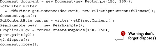
Drawing Shapes to PDFGraphics2D
In listing 14.12 you’ll reuse the code from listing 14.11. You’ll construct a JPanel, more specifically a PearExample object, create a PdfGraphics2D instance, and draw the JPanel to PdfGraphics2D using the paint() method. Don’t forget to use the dispose() method ![]() , or you’ll end up with unpredictable errors in the resulting PDF file.
, or you’ll end up with unpredictable errors in the resulting PDF file.
Listing 14.12. PearToPdf.java
Observe that there’s not a single line referring to iText in the PearExample constructor, nor in its paint() method. This is a very powerful feature. If you have an existing application that draws shapes to a Graphics2D object, you can use this code snippet to add these shapes to a PDF file.
Figure 14.8 shows how you can integrate charts generated with the JFreeChart library into a PDF file through the PdfGraphics2D mechanism.
Figure 14.8. Combining JFreeChart and iText

The pie chart in figure 14.8 was created using the next code snippet. It charts the result of a database query selecting nine directors and the number of movies by these directors in the movie database.
Listing 14.13. DirectorCharts.java

Again, there’s no reference to iText in this method. The iText magic happens here:
Listing 14.14. DirectorCharts.java (continued)

In this code snippet, you obtain a PdfGraphics2D object from a PdfTemplate. This makes it easier to position the chart on the page.
Troubleshooting PdfGraphics2D Applications
So far, the Graphics2D examples have been simple compared to the previous examples in this chapter. It would be surprising if there weren’t any caveats.
Numerous developers have posted problems to the mailing list that can be avoided by following these guidelines:
- Don’t forget to call the dispose() method once you’ve finished drawing to the PdfGraphics2D object ( in listing 14.12). Seriously, this is an FNA: a Frequently Needed Answer.
- The coordinate system in Java’s Graphics2D is different from the default coordinate system in PDF’s graphics state. The origin of user space in Java Graphics is the upper-left corner of the component’s drawing area. The X coordinate increases to the right; the Y coordinate increases downward.
- Java works in standard Red-Green-Blue (sRGB) as the default color space internally, but colors need to be translated. Be aware that anything with four color values is assumed to be ARGB, even when it’s probably CMYK. (ARGB includes the RGB components plus an alpha transparency factor that specifies what happens when one color is drawn over another.)
- Watch out when using fonts. There’s a big difference between the java.awt.Font and com.itextpdf.text.Font font classes. We’ll discuss this in section 14.5.2.
- It’s possible that you’ll need to install a virtual X11 server to make the examples involving Java’s Abstract Window Toolkit (AWT), such as the Graphics2D examples, work on Linux servers.
Let’s have a closer look at the last point in the list. If you use java.awt classes in applications on Linux servers, you can get exceptions like, “Can’t connect to X11 window server using xyz as the value of the DISPLAY variable” or “No X11 DISPLAY variable was set, but this program performed an operation which requires it.” The former error message occurs when a DISPLAY variable was set, but there was no X display server running. The latter occurs when there’s no DISPLAY variable set at all.
The Sun AWT classes on UNIX and Linux have a dependency on the X Window System. You must have X installed in the machine; otherwise none of the packages from java.awt will be installed. If you use these classes, they’ll attempt to load X client libraries and try to talk to an X display server. This makes sense if your client has a GUI. Unfortunately, it’s required even if your application uses AWT but, like iText, doesn’t have a GUI.
In some cases, you can work around this issue by running the AWT in headless mode. This can be achieved by starting the Java Virtual Machine (JVM) with the parameter java.awt.headless=true. In other cases, you’ll have to install a virtual X server. Xvfb, for instance, emulates an X server without outputting it to the monitor.
Suppose you’re working on Fedora Linux—you could install Xvfb using this line:
yum install xorg-x11-server-Xvfb
Once Xvfb is started, you can execute it like this:
Xvfb :100 -ac
Before starting your application, export the DISPLAY variable like this:
export DISPLAY=:100.0
You’ll have to do something similar for other Linux distributions; Please consult your Linux manual for the correct commands to install a virtual X server.
In the next section, we’ll look at how to render text using Graphics2D.
14.5.2. Drawing text to PdfGraphics2D
Drawing text to a Graphics2D object is straightforward:
g2d.setFont(new java.awt.Font("SansSerif", Font.PLAIN, 12));
g2d.drawString("Hello World", 36, 54);
Drawing the same text to a PdfGraphics2D object isn’t as trivial as the previous examples suggest. In the code snippet, you tell Java to use a java.awt.Font named “SansSerif”, but how does iText know where to find such a font?
Using a FontMapper
One way to deal with the difference between the way fonts are handled in AWT and in PDF is to create the PdfGraphics2D object and pass in an instance of the FontMapper interface:
FontMapper mapper = new DefaultFontMapper();
Graphics2D g2d = cb.createGraphics(width, height, mapper);
The font mapper interface has two methods. One returns an iText BaseFont when you pass a Java AWT Font, and the other returns a Java AWT Font when you pass an iText BaseFont:
public BaseFont awtToPdf(java.awt.Font font);
public java.awt.Font pdfToAwt(BaseFont font, int size);
Every class implementing this interface needs to establish a mapping between the two font objects.
There’s a default font mapper class called DefaultFontMapper. This class maps the following AWT font names to the standard Type 1 fonts:
- DialogInput, Monospaced, and Courier— Mapped to a font from the Courier family.
- Serif and TimesRoman— Mapped to a font from the Times-Roman family.
- Dialog and SansSerif— Mapped to a font from the Helvetica family (this is also the default if the font name isn’t recognized).
You can get the names of the font families that are available in AWT like this:
GraphicsEnvironment ge = GraphicsEnvironment.getLocalGraphicsEnvironment();
String[] fontFamily = ge.getAvailableFontFamilyNames();
On Windows, you’ll get names such as these:
Arial
Arial Black
Arial Narrow
Arial Unicode MS
These names won’t be recognized by the DefaultFontMapper unless you help the mapper by inserting a directory. In the next listing, you add all the fonts that are present in the directory c:/windows/fonts and list the fonts that were registered.
Listing 14.15. Graphics2DFonts.java

The insertDirectory() method will examine all the font files in that directory, get the name of each font, and add it to a map. You can get the entries in this map with the getMapper() method.
If you search the results of listing 14.15 for the Arial family, you’ll see that DefaultMapper has found four matches in the fonts directory on Windows:
Arial: c:windowsfontsarial.ttf
Arial Bold: c:windowsfontsarialbd.ttf
Arial Italic: c:windowsfontsariali.ttf
Arial Bold Italic: c:windowsfontsarialbi.ttf
In addition to getMapper(), there’s a getAliases() method that returns all the names that can be used to create the Java AWT Font object. This includes the name of the font in different languages, provided that the translations are present in the font file. You can also add your own aliases with the putAlias() method. All of these aliases can be used when creating a java.awt.Font object.
We’ve solved one major problem with DefaultFontMapper: how to map the name of a font in Java with the path to a font for iText. But what about the encoding?
Choosing a Different Encoding
Figure 14.9 shows a JPanel containing English and Japanese text.
Figure 14.9. Demonstration and solution of the encoding problem

The text was added to the JPanel in the paint() method of the next listing. It specifies a SansSerif font and MS PGothic.
Listing 14.16. TextExample1.java
public class TextExample1 extends JPanel {
  private static AttributedString akira;
  public TextExample1() {
    akira = new AttributedString(
      "Akira Kurosawa: u9ed2u6fa4 u660e or u9ed2u6ca2 u660e; "
      + "23 March 1910 – 6 September 1998.");
    akira.addAttribute(TextAttribute.FONT,
      new Font("SansSerif", Font.PLAIN, 12));
    akira.addAttribute(TextAttribute.FONT,
      new Font("SansSerif", Font.BOLD, 12), 0, 15);
    akira.addAttribute(TextAttribute.FONT,
      new Font("MS PGothic", Font.PLAIN, 12), 16, 20);
    akira.addAttribute(TextAttribute.FONT,
      new Font("MS PGothic", Font.PLAIN, 12), 24, 28);
  }
  public void paint(Graphics g) {
    Graphics2D g2d = (Graphics2D) g;
    g2d.drawString(akira.getIterator(), 10, 16);
  }
}
In this listing, you try to draw the content of the JPanel to PDF.
Listing 14.17. Text1ToPdf1.java
DefaultFontMapper mapper = new DefaultFontMapper();
mapper.insertDirectory("c:/windows/fonts/");
Graphics2D g2 = canvas.createGraphics(600, 60, mapper);
TextExample1 text = new TextExample1();
text.paint(g2);
g2.dispose();
If you search the map generated by the example listing, you’ll discover that the mapper is able to find the correct font:
MS PGothic: c:windowsfontsmsgothic.ttc,1
But the Japanese text isn’t rendered because the DefaultFontMapper assumes that each font uses the encoding Cp1252 (WinAnsi). This won’t work for Japanese.
You can fix this by adding a custom BaseFontParameters object to the mapper as was done here.
Listing 14.18. Text1ToPdf2.java

An alternative to this approach would be to subclass the DefaultFontMapper so that it uses a different encoding, or even a different font.
Custom Implementations of the FontMapper
You can render the text shown in figure 14.10 to PDF using three different strategies: by creating a custom FontMapper forcing the PdfGraphics2D object to use MS Arial Unicode with encoding Identity-H, by using AsianFontMapper, or by adding the glyphs as shapes instead of characters stored in a font.
Figure 14.10. Different strategies for drawing Asian fonts
Experienced Java programmers won’t like the paint() method in the next listing, but we’ll look at rewriting the code in listing 14.21.
Listing 14.19. TextExample2.java
private LineBreakMeasurer lineMeasurer;
public static final String AKIRA =
  "Akira Kurosawa (u9ed2u6fa4 u660e or u9ed2u6ca2 u660e, " +
  "Kurosawa Akira, 23 March 1910 – 6 September 1998) was a " +
  "Japanese film director, producer, screenwriter and editor. " +
  "In a career that spanned 50 years, Kurosawa directed 30 films. " +
  "He is widely regarded as one of the most important and " +
  "influential filmmakers in film history.";
public TextExample2() {
  akira = new AttributedString(AKIRA);
  akira.addAttribute(
    TextAttribute.FONT, new Font("Arial Unicode MS", Font.PLAIN, 12));
}
public void paint(Graphics g) {
  Graphics2D g2d = (Graphics2D) g;
  g2d.setFont(new Font("Arial Unicode MS", Font.PLAIN, 12));
  if (lineMeasurer == null) {
    AttributedCharacterIterator paragraph = akira.getIterator();
    paragraphStart = paragraph.getBeginIndex();
    paragraphEnd = paragraph.getEndIndex();
    FontRenderContext frc = g2d.getFontRenderContext();
    lineMeasurer = new LineBreakMeasurer(paragraph, frc);
  }
  float breakWidth = (float)getSize().width;
  float drawPosY = 0;
  lineMeasurer.setPosition(paragraphStart);
  int start = 0;
  int end = 0;
  while (lineMeasurer.getPosition() < paragraphEnd) {
    TextLayout layout = lineMeasurer.nextLayout(breakWidth);
    drawPosY += layout.getAscent();
    end = start + layout.getCharacterCount();
    g2d.drawString(AKIRA.substring(start, end), 0, drawPosY);
    start = end;
    drawPosY += layout.getDescent() + layout.getLeading();
  }
}
The drawString() method is similar to iText’s showTextAligned() method. It doesn’t wrap the text when the end of the line is reached. Figure 14.10 shows a longer text containing English and Japanese spanning multiple lines.
Here, you’re dividing the long AKIRA text into smaller String objects using the LineBreakMeasurer object with an AttributedString. The substrings are added using the drawString() method.
Creating a Custom FontMapper
The first of the three proposed strategies for rendering the text shown in figure 14.10 to PDF is to create a custom FontMapper class.
Listing 14.20. Text2ToPdf1.java
FontMapper arialuni = new FontMapper() {
  public BaseFont awtToPdf(Font font) {
    try {
      return BaseFont.createFont(
        "c:/windows/fonts/arialuni.ttf",
        BaseFont.IDENTITY_H, BaseFont.EMBEDDED);
    } catch (DocumentException e) {
      e.printStackTrace();
    } catch (IOException e) {
      e.printStackTrace();
    }
    return null;
  }
  public Font pdfToAwt(BaseFont font, int size) {
    return null;
  }
};
Graphics2D g2 = canvas.createGraphics(300, 150, arialuni);
This is a quick and dirty solution that forces PdfGraphics2D to use arialuni.ttf no matter which font was selected on the Java side.
Using AsianFontMapper
A similar solution is to use the AsianFontMapper class, as is done in the Text2ToPdf2 class, which demonstrates the second strategy for rendering the text:
Graphics2D g2 = canvas.createGraphics(300, 150,
  new AsianFontMapper(AsianFontMapper.JapaneseFont_Min,
    AsianFontMapper.JapaneseEncoding_H));
The AsianFontMapper class contains static String values corresponding with the CJK fonts discussed in section 11.3.3. One of the most difficult problems when using this approach lies with the font metrics. As far as the Java part is concerned, the font Arial Unicode is used. This choice is respected in the Text2ToPdf1 example in listing 14.20, but you use a different font in the Text2ToPdf2 example. This different font may have different metrics. If that’s the case, the size of each line will be different from what was expected. The text may even exceed the designated area.
Let’s consider a third strategy. You can drop the idea of using a FontMapper and let the Java code draw the shapes of the glyphs.
Drawing Glyph Shapes Instead of Using a PDF Font
If you create a PdfGraphics2D object using the createGraphicsShapes() method instead of createGraphics(), you don’t need to map any fonts. This is what happens in the example named Text2ToPdf3:
Graphics2D g2 = canvas.createGraphicsShapes(300, 150);
Internally, iText will use the Java object java.awt.font.TextLayout to draw the glyphs to the Graphics2D object. This object will address the font program directly and copy the path of each glyph to the page.
There’s a significant difference between this approach and using a FontMapper. If you open the Fonts tab in File > Properties, you won’t find any font. This has the following consequences:
- The file size will generally be larger because the glyph descriptions will be repeated in the content stream instead of being stored in a font stream from which they can be reused.
- Selecting text will be impossible because there is no text. Each glyph is a path that has been filled.
- Glyph resolution for glyphs that are stored in a font will render much better than glyphs drawn as shapes, such as when printed on low-resolution printers.
These are all disadvantages. An advantage could be that you will prevent end users from copying and pasting, or that you can obfuscate email addresses in your document so that they can’t be “harvested” by engines spidering your PDF. Finally, there’s the advantage that Java supports Hindic languages, whereas iText can’t make the ligatures when writing Hindi.
This phenomenon is also a side effect of using the LineBreakMeasurer correctly. The following example is a rewrite of listing 14.19.
Listing 14.21. TextExample3.java
private LineBreakMeasurer lineMeasurer;
private static AttributedString akira;
public TextExample3() {
  akira = new AttributedString(
    "Akira Kurosawa (u9ed2u6fa4 u660e or u9ed2u6ca2 u660e, " +
    "Kurosawa Akira, 23 March 1910 – 6 September 1998) was a " +
    "Japanese film director, producer, screenwriter and editor. " +
    "In a career that spanned 50 years, Kurosawa directed 30 films. " +
    "He is widely regarded as one of the most important and " +
    "influential filmmakers in film history.");
    akira.addAttribute(
      TextAttribute.FONT, new Font("SansSerif", Font.PLAIN, 12));
    akira.addAttribute(
      TextAttribute.FONT, new Font("SansSerif", Font.BOLD, 12), 0, 14);
    akira.addAttribute(
      TextAttribute.FONT, new Font("MS PGothic", Font.PLAIN, 12), 16, 20);
    akira.addAttribute(
      TextAttribute.FONT, new Font("MS PGothic", Font.PLAIN, 12), 24, 28);
}
public void paint(Graphics g) {
  Graphics2D g2d = (Graphics2D) g;
  if (lineMeasurer == null) {
    AttributedCharacterIterator paragraph = akira.getIterator();
    paragraphStart = paragraph.getBeginIndex();
    paragraphEnd = paragraph.getEndIndex();
    FontRenderContext frc = g2d.getFontRenderContext();
    lineMeasurer = new LineBreakMeasurer(paragraph, frc);
  }
  float breakWidth = (float)getSize().width;
  float drawPosY = 0;
  lineMeasurer.setPosition(paragraphStart);
  while (lineMeasurer.getPosition() < paragraphEnd) {
    TextLayout layout = lineMeasurer.nextLayout(breakWidth);
    drawPosY += layout.getAscent();
    layout.draw(g2d, 0, drawPosY);
    drawPosY += layout.getDescent() + layout.getLeading();
  }
}
You draw() the substring available in the TextLayout object instead of taking substrings of the long text and using drawString(). Using TextLayout.draw() has the same effect as using createGraphicsShapes() instead of createGraphics(). The same disadvantages apply: problems with file sizes, selecting text, and resolution.
Suppose that you want to mix different fonts and styles in one String, force line breaks, and avoid the disadvantages of using draw(). To do this, you’ll need another solution.
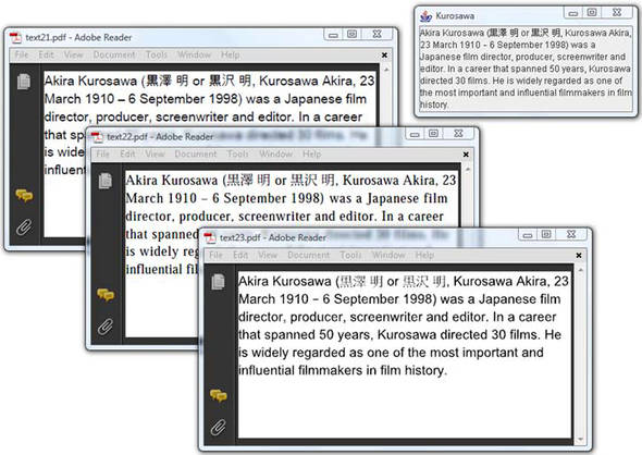
The upper-right PDF in figure 14.11 is drawn using listing 14.21. There are no fonts in the PDF; the glyph descriptions are added as PDF syntax in the content stream.
Figure 14.11. Different strategies for using mixed fonts

The lower-right PDF uses a different mechanism. It’s the result of printing a JTextPane to a PdfGraphics2D object.
Printing Swing Components to Pdf
The Java class java.awt.Component has a method named print() that takes a Graphics object as a parameter. You can use this method to print any component to a PdfGraphics2D object: JTables, JTrees, and so on.
The next listing creates a JTextPane and adds the different components of a text to a StyledDocument. The JTextPane will make sure the content is distributed over different lines, and render it correctly using the right fonts. The JTextPane is shown in the bottom-left window in figure 14.11.
Listing 14.22. TextExample4.java

The JTextPane class extends the Component class, and you’ll use its print() method in the next listing.
Listing 14.23. Text4ToPdf.java

This technique is frequently used in Swing applications. For instance, if you have an application with a JTable that’s shown on the screen, you can print that JTable to PDF using its print() method instead of using PdfPTable.
Note
The two methods for creating a PdfGraphics2D object, createGraphics() and createGraphics2D(), also exist with two extra parameters: convertImagesToJPEG and quality. Use these parameters to tell iText that it should convert all the images that are added to JPEGs. This can be an interesting way to reduce the size of the resulting PDF document. The quality parameter has the same meaning as the parameter with the same name in section 10.2.6.
In the next chapter, you’ll use the PdfGraphics2D class to convert files in the Scalable Vector Graphics (SVG) format to PDF. Right now, it’s time to summarize what this chapter was about.
14.6. Summary
We started this chapter by peeking into the content stream of a page, and we were confronted with PDF syntax for stroking and filling paths and shapes. To understand this syntax, we first looked at path construction and painting operators, and then we moved on to the operators that change the graphics state. The coordinate system received our special attention. Along the way, you learned about some convenience methods provided by iText.
We did the same for text and text state, looking at reference tables listing all the methods that are available in the PdfContentByte object. Then we repeated more or less what we did before, drawing paths and shapes and drawing text, but we didn’t use any of the methods discussed previously. Instead, we used the standard Java methods that are available in the abstract class PdfGraphics2D.
In the next chapter, we’ll continue examining the content of a PDF page, but we’ll focus on optional content and PDF tags. We’ll also try to parse a content stream to extract text from a page.