
Chapter 20
Production Sound
Four Digital Portable Sound Recorders
Nearly every director I have worked with in postproduction jumps up and down insisting on how much he or she wants the magic of production, but in reality so many of them do not do their part to assist the production mixers and their teams to bring that magic of performance to its fullest possible potential. So many times the opportunities are lost in the logistical heat of battle, in the sheer struggle of shooting the film and getting the shot before they lose the light. If ever a phase of the creation of the motion picture cried out for the discipline and regimentation of a military operation, it is the challenging battlefield of production.
ZAXCOM DEVA 5.8 AND DEVA 16
The Zaxcom Deva series are direct-to-disk digital audio recorders. The Deva was really the first professional field direct-to-disc digital recorder that overcame the sensitivity factor of traditional computer disk recording systems in the later 1990s. This production sound mixer brings a highly durable machine into any location recording scenario.
Front Panel Descriptions
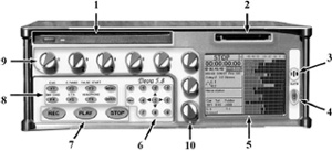
Figure 20.1 Deva front panel. Photo courtesy of Zaxcom Corporation.
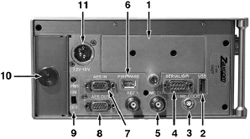
Figure 20.2 Deva left panel. Photo courtesy of Zaxcom Corporation.
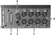
Figure 20.3 Deva right panel.
Left Panel Descriptions
1. |
Hard Drive Compartment |
2. |
USB Port: This port is designed to connect Zaxcom approved keyboards. |
3. |
Time Code Connector: This is the standard 5 pin Lemo connector used for Time Code I/O (Lemo part number: EGG.OB.305.CLL) |
4. |
Serial/RS422 connector: This 9-pin connector is used for controlling the Deva using an external device such as the Zaxcom Deva MIX-12 mixer. |
5. |
Word Clock Output: This BNC connector provides a word clock timing output generated internally from the Deva. |
6. |
IEEE 1394 (FireWire) connector: This is a FireWire 400 port which can be used with FireWire hard drives, CD, and DVD-RAM drives. If the external FireWire device requires power, it can be turned on from the My Deva menu. |
7. |
AES Digital Input Connector: Connect the supplied AES Digital input cable to this 15-pin mini sub-D connector. The cable provides four pairs of AES inputs. |
8. |
AES Digital Output Connector: Connect the supplied AES Digital output cable to this 15-pin mini Sub-D connector. The cable provides four pairs of AES digital output. |
9. |
Power Switch and LED: When the Deva is powered on the green LED illuminates. |
10. |
Battery Compartment: The black knob rotates to lock the battery compartment door. Use NP-1 type batteries with the Deva. You can safely use Li-ion and NiMH NP-1 batteries in the Deva as long as their maximum voltage does not exceed 18 VDC. |
11. |
Power Input Connector: Standard 4-pin XLR connector for 9.5 V-18 VDC 1 Amp input. Note: At this time the REF 1 connector does not function. |
Right Panel Descriptions
Using a keyboard off to the side of the unit, the recording mixer enters the scene, angle, and take data (that show up in the “slate” icon in the upper right-hand corner of the front panel). This entry along with the timecode is embedded in the directory of the audio file itself (metadata), thereby streamlining and removing possible errors by the assistant picture editor later in assimilating the material into the nonlinear editing system being used.
SOUND DEVICES DIGITAL RECORDERS
The introduction of Sound Devices 7-Series recorders in 2004 redefined the category of file-based recorders for production sound. Their extremely compact size and high feature content made them the first product capable of being a legitimate replacement for timecode DAT. While file-based recorders for production sound have been available since 1998 (when the Zaxcom Deva was introduced) their use was limited to only the largest feature films. Sound Devices 7-Series moved file-based recording into the hands of sound engineers recording effects, reality television, episodic television, commercial spots, documentary film and video, and feature film.
The 7-Series recorders were originally targeted to sound engineers working in over-the-shoulder environments. The units’ controls, size, and complement of connectors is more specific to “bag” work versus cart work. Because the recorder is typically used alongside a field mixer, wireless systems, and power distribution in a single production bag, it needs to be as compact as possible. Additionally, only two sides can be used for connectors and only one control surface is practical in bag applications. Other portable products are available with controls on secondary surfaces, but these are less common in portable applications.

Figure 20.4 The Sound Devices 744T multiple channel digital sound recorder, front panel. Photo courtesy of Sound Devices Corporation.
The transition to file-based recording opens numerous options and challenges to the engineer. The 7-Series has much depth in its choices of file type, sampling rate, timecode rate, and file management that tape-based systems never offered.
The Sound Devices 744T is a hardy portable four-track digital field recorder with timecode capability. The super-compact 744T records and plays back audio to and from its internal hard drive or Compact Flash medium, making field recording simple and fast. It writes and reads uncompressed PCM audio at 16 or 24 bits with sample rates between 32 kHz and 192 kHz. Compressed (MP3) audio playback and recording from 64 kb/s to 320 kb/s are also supported. The timecode implementation makes the 744T ready for any recording job-from over-the-shoulder to cart-based production.
The 744T implements a no-compromise audio path that includes Sound Devices’ next-generation microphone preamplifiers. Designed specifically for high-bandwidth, high-bit-rate digital recording, these preamps set a new standard for frequency response linearity, low distortion performance, and low noise. No other recorder on the market matches its size or feature set. In addition, its learning curve is quite short—powerful does not mean complicated. While the 744T is a very capable recorder by itself, it truly excels when used in conjunction with an outboard audio mixer such as Sound Devices’ 442 or 302.
Its two recording media (hard drive and Compact Flash) are highly reliable, industry standard, and easily obtainable. The removable, rechargeable battery is a standard Sony-compatible Li-ion camcorder cell. The 744T interconnects with Windows and Mac OS computers for convenient data transfer and backup.
Left Panel Connectors and Controls
1. |
XLR Input 1/AES3 INPUTS 1 & 2: Dual function input connection. Input type set with switch above. Active-balanced analog microphone or line-level input for input 1. Transformer-balanced two-channel AES3 input (1 and 2). |
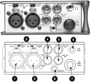
Figure 20.5 The Sound Devices 744t multiple channel digital sound recorder, left panel. Photo courtesy of Sound Devices Corporation.
Right Panel Connectors and Controls
1. |
Time Code Multi-Pin: Timecode input and output on 5-pin LEMO® connector. |
2. |
AES3id INPUTS 1 & 2 and 3 & 4: Unbalanced digital input accepts two channel AES3 (or S/PDIF) on BNC connectors. Supports sample rates up to 200 kHz. |
3. |
FireWire (IEEE-1394) Port: Connection to a computer to access the internal hard drive and Compact Flash volumes as mass storage devices. Direct connection to Mac OS (10.2 or higher) and Windows (XP-and 2000 only) computers. |
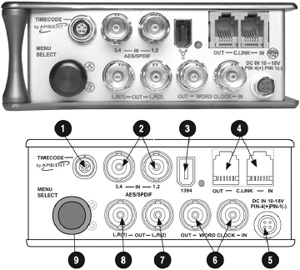
Figure 20.6 The Sound Devices 744T multiple channel digital sound recorder, right panel. Photo courtesy of Sound Devices Corporation.
FOSTEX PD-6 DIGITAL RECORDER
The Fostex PD-6 Multitrack DVD-RAM Recorder will record up to 6 tracks of 24-bit audio to an internal 8 cm DVD-RAM disc, or an internal 40 gig hard drive. This much anticipated nonlinear digital recorder boasts many useful features including: BWF recording file format; UDF (Universal Disc Format) which allows DVD-RAM discs to read instantly on both PC and Mac platforms; onboard timecode generator with ±1 ppm accuracy and a built-in pull-up/pull-down switch. This unit handles all timecode rates including 23.976 fps; IEEE1394 (FireWire) interface for fast backup and restore; USB keyboard port; 10-second pre-record buffer.
The PD-6 can also record 4 discrete tracks and a 2-track composite mix as separate files, or 5 tracks of discrete audio and a mono composite. Discs recorded on the PD-6 are instantly compatible with the Fostex DV40, and all files can be played back in a linear fashion, synced to timecode, or controlled via RS-422 on the DV40, making the PD-6 widely acceptable with a growing list of telecine and postproduction facilities.
Fostex PD-6 Front Panel
1. |
[POWER] switch: Turns on or off the main power of the PD-6. The switch is fitted back from the panel surface in order not to switch it accidentally. Note: If the [PANEL LOCK] switch is set to the “LOCK” position, you cannot turn off the power. |

Figure 20.7 The Fostex PD-6 multichannel digital sound recorder. Photo courtesy of Fostex Corporation.
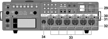
Figure 20.8 The Fostex PD-6 multichannel digital sound recorder, front panel functions. Photo courtesy of Fostex Corporation.

Figure 20.9 The Fostex PD-6 multichannel digital sound recorder, left panel functions. Photo courtesy of Fostex Corporation.
29. |
[DISC FEED] switches: Each switch selects a recording source of corresponding track. Channel pre-fader signal is selected. Stereo bus (L or R) signal is selected. The “L” signal can be assigned to the odd tracks, while the “R” signal can be assigned to the even tracks. Channel post-fader signal is selected. |
30. |
[PEAK] indicators: Each indicator lights up according to the input level of the input amplifier. Lights in green: The input level is between –1 dB and –5dB of the clipping level. Lights in red: The input level is between 0 dB and –1dB of the clipping level. By setting “Input Clip” in the “Error tone” menu of the Setup mode to “On,” the error tone is output from the monitor speaker (or headphones) whenever the corresponding input channel receives a loud signal which makes the indicator light up red. |
31. |
[PFL] keys: By pressing a [PFL] key, you can hear the pre-fader signal of the corresponding channel from the internal monitor speaker or headphones. When any of the [PFL] keys is pressed, the pre-fader signal takes priority to the signal selected by the monitor selection switches (SOLO monitor select switch, Monitor mode select switch, and ST/MONO monitor select switch). |
Fostex PD-6 Left Panel
1. |
[ANALOG LINE OUT] connectors: These connectors feed analog audio signals of tracks 1 through 6. Connectors: XLR-3-32 type (balanced). |
2. |
Internal monitor speaker: Outputs track audio signals, error tones, etc. When a headphone plug is inserted to the [PHONES] jack, the monitor speaker is inactive. |
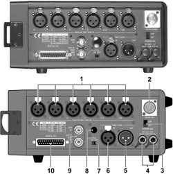
Figure 20.10 The Fostex PD-6 multichannel digital sound recorder, right panel functions. Photo courtesy of Fostex Corporation.
3. |
[AUX I/O] connector: The input ports of the [AUX I/O] connector receive audio signals and route them to the monitor circuit, while the output ports feed stereo bus signals. You can select the output level from among three options using the [AUX OUT ATT] switch. |
4. |
[AUX OUT ATT] switch: Switches the output level of signals sent from the output ports of the [AUX I/O] connector among +4 dBu, –10 dBu, and –60 dBu. |
5. |
[REMOTE] connector: This connector accepts parallel remote signals for controlling the PD-6 externally. Connector: MINI DIN 8-pin. You can control the following nine operations remotely. Operation note: When a terminal is grounded, the function is active. Note that you can always control the PD-6 via this connector regardless of the setting of the [PANEL LOCK] key on the panel. Caution note: Pin 7 (DC 12 V) supplies the PD-6 operation voltage. If it is short-circuited to GROUND, or used with a heavy load, the PD-6 internal battery life may be exhausted faster or the PD-6 may generate heat abnormally. Be careful not to use it with a heavy load or short-circuit it to GROUND. |
6. |
[USB] connector: Used to connect to a USB keyboard, allowing you to control the PD-6 from the keyboard. |
7. |
[EJECT] lever: Used to remove the internal battery (NP-1 type) from the battery compartment. |
8. |
Battery compartment: Stores the battery (NP-1 type). |
Fostex PD-6 Right Panel
AATON CANTAR-X DIGITAL RECORDER
The Cantar-X features the ability to record up to 8 discreet tracks of 24-bit/96 kHz audio to either an internal 60 gig hard drive or an external hard drive or optical drive via its built-in 6-pin FireWire connector providing over 57 hours of 2-track 48 kHz/24-bit audio and over 7 hours of 8 track 96 kHz/24-bit.
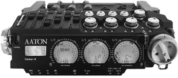
Figure 20.11 The Aaton Cantar-X multiple channel digital sound recorder, front panel. Photo courtesy of Aaton.
Any one of the Cantar's 5 transformer balanced mic-pres, 4 analog Line level, or 8 AES digital inputs can be routed to any track, or multiple tracks, quickly and easily in Cantar's intuitive routing input menu. Changes to routing or monitoring can be achieved on the fly by recalling custom presets that are stored in its nonvolatile memory. Phantom power, limiters, phase reverse, and an adjustable hi-pass filter are switchable for each microphone input. A stereo mixdown of the discrete tracks can be recorded as a separate file and/or routed to any of the Cantar's two adjustable line level analog outputs, AES digital output or headphone matrix.
A unique magnetic fader panel is provided for creating the stereo down-mix in the field and for controlling pan and PFL solo checking for each track. The stereo mixdown file, the discrete tracks, or all can be burned at the end of the day to either an optional internal optical drive or an external FireWire drive, and the Cantar allows you to choose between CD-R, DVD-R, or DVD-RAM formats so your resulting discs will realize a wide cross-platform compatibility in the postproduction environment.
The Cantar interface is the easiest to use in the most difficult missions. It offers the largest display surface of all portable recorders which simultaneously show every critical recording parameter. The custom designed high contrast LCD displays remain visible under bright sunlight and at very low temperatures; and the swiveling front panel always offers the best viewing angle for both cart and over-the-shoulder work.
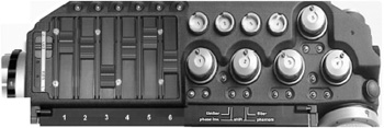
Figure 20.12 The Aaton Cantar-X multiple channel digital sound recorder, top panel. Photo courtesy of Aaton.
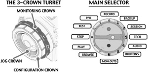
Figure 20.13 The Aaton Cantar-X multiple channel digital sound recorder, the jog wheel functions. Photo courtesy of Aaton.
The 3-Crown Turret
Monitoring crown:
1. |
So: 5 Mic inputs, 4 Line inputs, 6 Digi inputs, and active tracks are sent to the headphones as “solos.” |
2. |
Ph: mixer output and 17 users’ grids to headphones. |
3. |
Lo: mixer and 9 users’ grids to dual line-out. |
4. |
Fb: mixer and 9 users’ grids to dual foldback. |
5. |
Di: mixer and 9 users’ grids to dual digi-out (AES). Note: The headphones receive the same signal as the one sent to the output being configured. |
Config crown: In TEST and PPR, push the Solo-Mix-Pan slider battery side, press the routing button (top left of the swivelling panel), and rotate the config crown to browse the 15 Input-to-Track configs and to activate the one showing while the routing button is released. In REC, push the Solo-Mix-Pan slider battery side, press the routing button to verify the Input-to-Track configuration in use. Note: To avoid finger errors, the current configuration cannot be modified in REC but there is a shortcut: by switching to PPR you have plenty of time (up to 35 seconds) to select another configuration and go back to REC. This operation creates another file and does not lose any audio sample between the two. In REC, pull the Solo-Mix-Pan slider operator side, and press the routing button to turn the three circular screens into a large Mon-Outs “Left-Center-Right” display. Since this doesn't affect the recording signals, you can on-the-fly listen to and select another monitoring pattern by rotating the Config crown.
Jog crown: The “one finger” jog is used to move the cursor in the message panel, to edit Scene&Take, to select high-pass filters, to modulate the backlight, to control the pan pots, and to scrub the player in fast forward/reverse. Note: [Shift•Jog] 10x accelerates the jog speed.
The Main Selector
The large twelve position Main Selector eliminates diving into sub-directories, and because the unique three-crown turret gives instant access to all recording and monitoring configurations, even with gloves on.
Six “sound managing” positions: •REC •PPR •TEST •STOP •PLAY •BROWSE, laid out in the standard way.
Six “operand” positions: •MON-OUTS •ROUTE-INS •AUDIO •TECH •SESSION •BACKUP, give access to all the possible settings of the machine. The black, white, and red buttons are made for the thumb; they work together with the large blue key [shift] activated by the index.
IN TEST PPR REC:
[white] (reserved to insert prelocating marks).
[shift • white] in PPR opens/closes the editing pane.
[black] sends slate mic to line-out and foldback.
[shift •black] sends slate mic to tracks too.
[red] in PPR &REC toggles the take gender: “p” (pickup), “w” (wild sound), “t” (sync), “n” (ignore).
[shift • red] triggers the tone generator; tone stays “on” if SHIFT is released first.
IN PLAY:
[white] stops and starts the player from the marker.
[black] puts a start mark on the played position (to make a pause, press
[white] then [black]).
[shift • black] resets the player to 00.
IN INPUTS-TO-TRACKS & MON-OUTS:
[black] sets routing links, e.g., mic-in 3 to track 5.
[red] erases routing links.
Nine rotary analog faders plus six linear digital faders each entirely devoted to one specific task give more possibilities and are faster to handle than four multifunction knobs. All of Cantar's rotary knobs, faders, switches, and the enclosure itself are sealed against the elements to guard against damage caused by dust and moisture. Aaton's optional 12-volt rechargeable and re-cellable NiMH batteries connect to the Cantar via its dual 4-pin XLR DC inputs, providing up to 15 hours of autonomous operation in the field.

Figure 20.14 The Aaton Cantar-X multiple channel digital sound recorder, top view.

Figure 20.15 The Aaton Cantar-X multiple channel digital sound recorder's signal path. Photo courtesy of Aaton.
The Twin Battery Safety
The Cantar low power requirements-to-high efficiency electronics have the longest working time of all portable recorders. With a single set of onboard (NiMH) batteries, the Cantar works 15-to-18 hours easily.
External 12–16 V DC can also be used, maintaining compatibility with most common DC packages. An optional Bluetooth module provides two-way communication between the Cantar and a Bluetooth-enabled PDA to vividly display all of the Cantar's settings at a glance. The Aaton Cantar records Broadcast Wave files which can be directly imported to most popular editing systems.
Routing 15 Inputs to 8 Tracks
Six primary tracks, T1 through T6, can receive any one of the 15 independent and permanently active inputs: line 1, 2, 3, and 4 – mic inputs 1, 2, 3, 4, 5, Digi (AES) 1, 2, 3, 4, 5, and 6. Fifteen Inputs-to-Tracks configs can be stored. They are instantly recalled through the swiveling panel routing button and the “config” crown (a one-hand operation). The primary tracks are monitored by pairs T1T2, T3T4, T5T6 on the circular screens. Two eXtra tracks (Xa Xb), receive the reference sounds out of the built-in digital mixer. These reference sounds are clearly separated from the T1 to T6 primary tracks: they are displayed on the rectangular display bar graphs. They also can be displayed on the rightmost circular modulometer by pressing the [EYE] button. When the “Xa” “Xb” track pair is generated by the mixer, they are sent to tracks 7 and 8 and a “mix” icon shows on the circular displays. When recording 8 tracks and no mixdown, the 1 to 6 tracks are routed the standard way and the 7 and 8 tracks directly receive the signals selected in AUDIO-12: Line-in 3 and 4, or Mic3 and 4, or Aes-in 7 and 8, or nothing (this later position saves disk space).
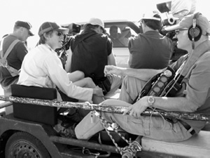
Figure 20.16 Production sound mixer Petur Hliddal strapped into the truck as he tackles the grueling task of capturing a clean production track on location for Syriana. Carl Fischer, boom operator.
Petur Hliddal, veteran sound mixer for such diverse styles of productions as Lucky You, The Aviator (2004 version), Big Fish, Divine Secrets of the Ya-Ya Sisterhood, Planet of the Apes (2001 version), and The Cider House Rules, talks about using the Cantar X on the challenging shoot of Syriana:
I just finished work on Syriana, an ambitious globetrotting thriller involving five parallel stories, which intersect and diverge, all related to the international oil business. We shot dialog scenes with two hand-held cameras, frequently with no lighting, in self-driven cars, boats, elevators, airplane cabins, and one 600’-long supertanker. This was in addition to the usual assortment of inaccessible locations—rooftops, schoolrooms, desert hideaways, odiferous Moroccan kebab shops, Pakistani construction workers’ shantytowns, desert power transmission line towers. Many of these locations were located far from the work trucks, on rough ground or sand, necessitating our using small departmental 4 × 4 pickups for equipment transport and storage.
At times the scenes we shot were loosely scripted or improvised and it was not unusual for us to be running four or five wireless mics together with M-S ambience tracks to help with uncontrolled backgrounds. When you are shooting far from trucks or carts, and the camera crews are hustling from moving car interiors to exterior drive-bys and back, shooting as fast as they can shoulder the camera and push the button, you have got to be light, fast, and flexible to keep up. The Cantar X could not have been more perfectly suited to the production problems I had to face and I could not have done nearly as good a job without it.
Our data traveled in two ways. When working on the cart, I mirrored the Cantar hard drive with a LaCie D2 DVD-RAM, which I shipped to the lab for warehousing. When over-the-shoulder, I used LaCie 60 GB pocket drives stuck in a carry-case pocket. These were shuttled between the lab where DVD-RAM copies were struck for warehousing, and our locations, where we reused them as needed. In addition, each weekend I loaded the Cantar drive to LaCie 120 GB hard drives on which I maintained a second file warehouse on location.
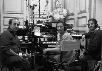
Figure 20.17 Production sound mixer Stuart Wilson (center) using three Cantar X recorders simultaneously to cover all of the wireless mics and ambience booms for the 2006 production of Marie Antoinette. Photo by Stephane Lioret, boom operator.
I have now completed two films with the Cantar X and I have to say for the first time since the “digital revolution” in film sound began, I feel I have stabilized my format decision-making.
Stuart Wilson, production mixer for projects such as Harry Potter and the Order of the Phoenix, The Constant Gardener, A Cock and Bull Story, Code 46, The Last Dreamers, The Intended, Room to Rent, Born Romantic, and The Last Yellow, to name just a few, shares his experience working with the Cantar X:
I'm just starting my next feature with the Cantar X and I think it's fantastic! From The Constant Gardener in the heat and dust of Northern Kenya and Sudan to the rain back in Europe, the faders and knobs are well sealed and have coped with a lot of rough treatment.
It's definitely enabled me to do things I wouldn't have been able to do otherwise; mostly for those running-around shots where one has to be portable, I've been able to have a boom and up to 5 radios and mix on the shoulder.
The latitude one has is very good; the self-noise is very low and the headroom very high, so much so that I'm getting a bit lazy having left some of my old analog gain riding technique to keep the signal within a healthy range as I know the recorder can cope with it.
On The Cock and Bull Story, the last Michael Winterbottom film, I was recording a scene with muskets and cannons and a crowd of extras: I set the levels so that the explosions wouldn't overload and recorded a couple of takes, but then you miss the value of having all those extras shouting in the heat of battle, so I decided to do a take with levels set for the crowd and I would let the explosions go over (thinking it is easier to add a cannon shot in post than recreate 200 screaming soldiers in the studio!). The crowds were sounding good and then the explosions started and the Cantar wouldn't distort! There was a good 30 dB difference in the levels I'd set and it sounded great! The limiters are incredible.
I had this interview with Bertolucci. He said he didn't want to post-synch (loop) anything, and he said that he wanted to shoot it in a real Paris apartment. I immediately asked him, “How is the floor?” Because I knew that all the apartment buildings in Paris use these parquet floors.
Then he answered, “Well, the floors in these Paris apartments, they have their own voice.”
I replied, “But we don't want that voice to become a character in the film.” So then I turned to the production manager and said, “I want to see the location.”
The production manager replied, “Well, you can't come. It's not finished yet and the art department is still doing stuff.”
I agreed, “Yeah, exactly that, when it's finished, it's too late! After all, the art department has done their stuff, dressing and everything. I have to be there before and see if there is anything we can do about any problems, and if we can, can they be worked into the schedule.”
The production manager tried to keep me away because he thought it was going to cause trouble or cost money. I wrote them an email and said that it was up to them—if I'd just arrive on the location site and it's already a fait accompli, then I cannot be held responsible for the sound. I will deal with what I could, and if that wasn't what they wanted, then that would be just fine! But if they wanted me to take the responsibility for the sound, and that is the way I prefer to work, then I needed to see the place to see if there was any preparation that needed to be done, or what could be done and what was practical. Obviously, they had to budget it, but I can give my proposals and then it's up to the producer and director.
Then they got nervous and said, “Okay, can you come tomorrow?”
So I went to Paris from my home in London and recommended some things. I said that they should double-glaze all the windows and they did it. In the main bedroom, where a lot of dialog was taking place, I talked to the production designer and he was thinking maybe he would have carpet on the wooden floor, and eventually, I was not only able to persuade him to have carpet in this room, but to lift the carpet out and lay a new wooden floor on top of the old creaky one and then put the carpet on top of that. That really helped us a lot!
An argument used in the defense of leaving a location the way it is, is that when the actors move around and it's creaking, then it's lifelike and it's natural and it can be nice and atmospheric. But the problem is, if the camera moves like when we had a Steadicam operator moving and the actors are still, then it's ridiculous and you can't use it because you just become aware of the camera and who's behind the camera.
The art department was very good. If they have two or three weeks to make some changes, screwing down floorboards, fixing door frames that don't fit properly or window frames that don't close properly, then they can do it. They can get a carpenter in for one day. It's not really a big expense. They can do it as long as they have the time to do it. If they don't have much time (e.g., if I'm not brought in until the last minute) then it's stress for them and everybody is busy and then it's a problem.
In the end they were very happy and toward the end of the shoot the French production manager came to me and said that he was very impressed because I'd been very clear and that the director was very pleased with the sound; in fact they only looped one scene, so it was worth the gamble of making myself unpopular during preproduction so when it came to shoot the prep work was done and we all could concentrate on trying to get quality rather than just getting something just usable.
THE ULTIMATE GOAL AND CHALLENGE
The challenges of production sound recording make it a difficult and arduous job. The production mixers and their teams face the daunting and often disheartening struggle with the ignorance factor of the producer(s) and director and their lack of personal empowerment by not knowing what is possible and what preparations and techniques can most efficiently accomplish the mission. If they do not understand what is possible (and they will not understand that unless you have at least certain tools and procedural protocols), and if they do not understand the importance of what “quiet on the set” really means, then how can they hope to deliver what is truly possible? How can they dream to deliver the magic opportunities of production sound?