Chapter 14
Lyotropic Chromonic Liquid Crystals: Emerging Applications
14.1 Introduction
Over the last 10 years since the early work of Attwood, Lydon, Tiddy, and co-workers [1–3] there has been a growing interest in a distinct family of lyotropic liquid crystals (LCs), the so-called lyotropic chromonic liquid crystals (LCLCs). LCLCs represent a broad but not well-understood class of soft matter in which the reversible self-assembled aggregates formed by non-amphiphilic molecules show liquid crystalline phases [4–7]. The range of materials which forms chromonic LC phases includes drugs [2, 3, 8–10], dyes [11–14], and DNA nucleotides, such as guanosine derivatives [15, 16]. The name “chromonic” was suggested by Lydon to carry connotations of dyes and chromosomes and of the bis-chromone structure of disodium cromoglycate (DSCG), also known as an anti-asthmatic drug cromolyn or INTAL, one of the first studied LCLCs [3, 5].
The LCLC molecules have a plank-like or disk-like polyaromatic central core with polar groups at the periphery. The geometry of the basic structural unit in LCLCs is different from spherical or cylindrical micelles and bilayers formed by amphiphilic molecules in the conventional lyotropic LCs. In water, the chromonic molecules typically stack on top of each other face-to-face (the so-called H-aggregation) to minimize the areas of unfavorable contact with water and leaving the ionic solubilizing groups at the aggregate–water interface. This structure has been proven by X-ray diffraction studies and polarized UV–vis spectroscopic measurements for many LCLCs [10, 14, 17–21]. The typical separation between the adjacent molecules along the stacking direction in H-aggregates is about 0.33–0.34 nm as measured by X-ray diffraction [10, 14, 19]. This value of the stacking distance does not depend on the chromonic concentration and the phase of solution, and represents a basic feature of the chromonic aggregates. When the polar groups are fully ionized, the line density of electric charge along the aggregate can be very high, for example, ~6e/nm (e is the electron's charge) for the LCLC molecules with two ionic groups. The stacking distance and the line charge make LCLC aggregates similar to the double-strand B-DNA molecules. The important difference is that in LCLCs, there are no chemical bonds to fix the length of aggregates.
The underlying mechanism of aggregate self-assembly in LCLCs is analogous to the process resulting in worm-like micelles formed by surfactant molecules in solutions and the so-called “living” polymerization. The aggregate would grow indefinitely if it were not for the entropy that decreases when the number of aggregates decreases. The balance of the “end” energy E of an aggregate (also called the scission energy, that is, the energy needed to cut an aggregate into two), and the entropy gained by producing more “ends”, results in the prediction of the broadly polydisperse system with an average aggregation number:
determined by the volume fraction ϕ of the solute and strongly dependent on E and the absolute temperature T, for example, Refs [22, 23]. As the concentration of a chromonic material increases, the aggregates multiply, elongate, and align parallel to the common direction, called the director ![]() . The two most commonly met phases are the uniaxial nematic (N) phase and the hexagonal columnar (C) phase, Figure 14.1. In earlier publications, one often finds the term “M phase”, where “M” stands for “middle.” We use the term “C phase” instead of “M phase” whenever the presence of a hexagonal columnar phase with aggregates forming a hexagonal lattice in the plane perpendicular to
. The two most commonly met phases are the uniaxial nematic (N) phase and the hexagonal columnar (C) phase, Figure 14.1. In earlier publications, one often finds the term “M phase”, where “M” stands for “middle.” We use the term “C phase” instead of “M phase” whenever the presence of a hexagonal columnar phase with aggregates forming a hexagonal lattice in the plane perpendicular to ![]() , is established [19, 24].
, is established [19, 24].
Figure 14.1 Schematic illustration of LCLC aggregates in (a) I phase, (b) N phase, and (c) C phase.

The aggregates' length depends not only on the concentration, but also on the specific details of molecular interactions, temperature [4, 25], ionic content [8, 19, 26–29], pH of the solution [19], and type of the side groups [4, 30]. The LCLCs, thus, represent an interesting self-assembled system with an orientational and positional order that is highly sensitive to a number of factors.
The recognition of LCLCs as a fascinating and distinct class of lyotropic LCs was not widespread just a few years ago. As one of the pioneers in this field, Lydon [5] wrote, “A single large-scale commercial application of chromonics will of course change this picture overnight ... the continuing discovery of unique properties and versatility of these systems promises much.” Recently, there have been several studies demonstrating the potential of chromonics for applications in functional materials and devices, such as optical polarizers [31, 32], optically anisotropic films [12, 33–35], biosensor [36, 37], micro-patterned films [38], nano-fabrication materials [39, 40], and organic electronics [41]. In this review, we focus on the recent studies of LCLCs and their potential applications.
14.2 Structures and Phase Properties of LCLCs
Even in the dilute isotropic (I) solutions, chromonic molecules have a strong tendency to stack into aggregates. The balance of energy gained by placing a chromonic molecule inside the aggregate and the entropy term promoting a larger number of aggregates produces a polydisperse system of linear aggregates [22, 23] that can arrange themselves into ordered LC phases as a function of concentration and temperature. The techniques commonly used to determine the phase behavior of LCLCs include polarizing optical microscopy, X-ray diffractometry, and NMR spectroscopy. Other techniques, such as dynamic light scattering, small-angle neutron scattering, transmission electron microscopy, and rheological measurement have also been used to characterize the aggregates of LCLCs.
14.2.1 Food Dye Sunset Yellow as LCLCs
Several previous studies demonstrated the aggregate structures and phase behavior of sunset yellow (SSY), one of the most typical LCLCs. SSY is a food coloring azo dye, having the chemical name disodium salt of 6-hydroxy-5-[(4-sulfophenyl)azo]-2-naphthalenesulfonic acid, Figure 14.2(a)–(b). SSY contains central aromatic groups, phenyl and naphthyl rings linked via an azo group with two solubilizing sulfonate groups attached to either end of the molecule. The liquid crystalline properties of SSY have been studied by Ormerod [42], Luoma [43], and recently by Horowitz et al. [14], Park et al. [19, 29], Edwards et al. [20], and Chami and Wilson [44]. Compared with other LCLCs, the aggregate structure of SSY has been somewhat better established. Most significantly, it has been shown that the stacks of SSY in water contain only one molecule in cross section and the SSY molecules are on average perpendicular to the aggregate axis [14, 19, 20, 44]. The average diameter dSSY of the aggregate, according to Edwards et al. [20], is about 1 nm, while Luoma [43] found dSSY = 1.4 nm.
Figure 14.2 The molecular structure of two forms of SSY, (a) NH hydrazone tautomer: prevailing form in aqueous solution [19, 20] and (b) OH azo tautomer. Phase diagram (c) and polarizing micrographs (d)–(g) of SSY water solutions. The error bars represent the difference between the data taken on heating (upper end of the bar) and cooling (lower end of the bar). The filled circles at the vertical line indicate the temperatures at which the pictures (d)–(g) were taken.
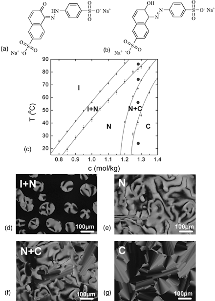
The phase diagram of SSY [19] shows the I, N, and C phases with broad coexistence regions, Figure 14.2(c). The N phase produces Schlieren textures with disclinations (characterized by two dark brushes of extinction) and point defects-boojums (with four brushes of extinction), Figure 14.2. The columnar phase shows characteristic “developable” domains [45].
14.2.1.1 X-ray Diffraction Measurement of SSY Water Solutions
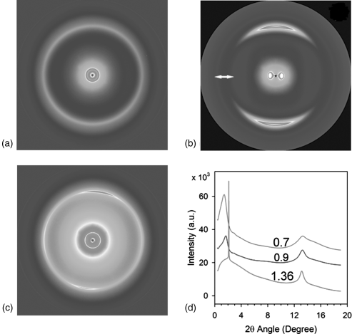
X-ray diffraction measurement is an important technique not only for the phase identification but also for the characterization of LCLC aggregates. Several previous studies used X-ray measurements to characterize SSY aggregate structures [14, 19, 24]. Figure 14.3 shows the typical X-ray diffraction patterns of the I phase of 0.7 mol/kg, N phase of 0.9 mol/kg, and C phase of 1.36 mol/kg SSY solutions [19]. In the I phase of SSY solution, cSSY = 0.7 mol/kg, the aggregates have no orientational order, Figure 14.3(a). Since SSY molecules possess positive anisotropic magnetic susceptibility, they orient parallel to the direction of the magnetic field. Consequently, the director ![]() , the common direction of aggregates, aligns perpendicularly to the magnetic field. The walls of circular capillaries containing the sample for X-ray studies assist in a uniform alignment of
, the common direction of aggregates, aligns perpendicularly to the magnetic field. The walls of circular capillaries containing the sample for X-ray studies assist in a uniform alignment of ![]() along the axis of the capillary, so that the magnetic field is typically directed perpendicularly to the sample. The diffraction pattern of the aligned N phase has two pairs of arcs in orthogonal directions, Figure 14.3(b). This feature supports the model of H-aggregation [46], with the molecules stacked on top of each other, being on average perpendicular to
along the axis of the capillary, so that the magnetic field is typically directed perpendicularly to the sample. The diffraction pattern of the aligned N phase has two pairs of arcs in orthogonal directions, Figure 14.3(b). This feature supports the model of H-aggregation [46], with the molecules stacked on top of each other, being on average perpendicular to ![]() . One pair of arcs in the vertical direction at the large angle (2θ = 13.2°) ascribed to the stacking distance (az = 0.33 nm) along
. One pair of arcs in the vertical direction at the large angle (2θ = 13.2°) ascribed to the stacking distance (az = 0.33 nm) along ![]() remains the same in the I and C phases, indicating that the space between chromonic molecules within an aggregate is not altered by the concentration of SSY. Another pair of arcs in the horizontal direction is from the small angle diffraction, related to the average distance between the SSY aggregates.
remains the same in the I and C phases, indicating that the space between chromonic molecules within an aggregate is not altered by the concentration of SSY. Another pair of arcs in the horizontal direction is from the small angle diffraction, related to the average distance between the SSY aggregates.
Figure 14.3 Typical X-ray patterns (a)–(c) of SSY water solutions at different concentrations SSY c: (a) I phase, SSY c = 0.7 mol/kg; (b) N phase, SSY c = 0.9 mol/kg; (c) C phase, SSY c = 1.36 mol/kg. The arrow in (b) represents the direction of the magnetic field; (d) diffractographs of SSY water solutions at different concentrations SSY c : 0.7 mol/kg (green), 0.9 mol/kg (blue), and 1.36 mol/kg (red). (Redrawn from Park et al. [19].)
One can determine the correlation length ξL,SSY corresponding to the stacking repeat distance, that is, inversely proportional to the full width at half maximum (FWHM) of the scattering wave vector peak. One finds that ξL,SSY increases with the concentration of SSY [19, 24]. However, ξL,SSY is much smaller than the true (average) length ![]() L
L![]() of aggregates. For example, the correlation length for 0.9 mol/kg N phase SSY is ξL,SSY = 3.5 nm [19]. This quantity is much smaller than the minimum length Lmin of aggregates capable to form an N phase in the Onsager model of identical thin rods, Lmin ≈ 4dSSY/ϕSSY ≈ 20 nm [47]. Park et al. [19] have suggested that the chromonic aggregates may possess defects and branches, in which case the X-ray coherence can be lost but a physical connection remains, Figure 14.1(b). Recent measurement by Renshaw and Day [48] of the diffusion coefficients by NMR spectroscopy also demonstrated that the length of SSY aggregates is larger than the correlation length measured by X-ray diffraction.
of aggregates. For example, the correlation length for 0.9 mol/kg N phase SSY is ξL,SSY = 3.5 nm [19]. This quantity is much smaller than the minimum length Lmin of aggregates capable to form an N phase in the Onsager model of identical thin rods, Lmin ≈ 4dSSY/ϕSSY ≈ 20 nm [47]. Park et al. [19] have suggested that the chromonic aggregates may possess defects and branches, in which case the X-ray coherence can be lost but a physical connection remains, Figure 14.1(b). Recent measurement by Renshaw and Day [48] of the diffusion coefficients by NMR spectroscopy also demonstrated that the length of SSY aggregates is larger than the correlation length measured by X-ray diffraction.
The X-ray of a cSSY = 1.36 mol/kg C phase at small angle 2θ = 2.1° shows a strong sharp diffraction line and three faint, but sharp diffraction lines d2, d3, d4 whose diffraction spacings are in the ratio of ![]() , characteristic of the hexagonal structure, Figure 14.3(c) [10, 17]. The inter-aggregate axis-to-axis distance D can be directly related to these diffraction lines,
, characteristic of the hexagonal structure, Figure 14.3(c) [10, 17]. The inter-aggregate axis-to-axis distance D can be directly related to these diffraction lines, ![]() , Table 14.1. The correlation length ξD,SSY, associated with the positional order transverse to the aggregate axes determined from the FWHM of the peak at 2θ = 2.1° is much larger than the corresponding value in the N phase, Table 14.1.
, Table 14.1. The correlation length ξD,SSY, associated with the positional order transverse to the aggregate axes determined from the FWHM of the peak at 2θ = 2.1° is much larger than the corresponding value in the N phase, Table 14.1.
Table 14.1 X-ray diffraction data for four different concentrations of SSY in water, expressed in molal cSSY (mol/kg) and volume fraction ϕSSY units. The temperature is fixed at 28.4°C.

14.2.2 Anti-Asthmatic Drug DSCG as LCLCs
Disodium cromoglycate (DSCG) is widely known as an antiasthmatic drug. It is one of the most extensively studied LCLC materials. However, the details about the aggregate structure of DSCG are still the subject of discussion. Hartshorne and Woodard [10] assumed that there is one molecule in the cross-section of the cylindrical aggregate of DSCG. They estimated the cylinder diameter to be about 1.6 nm. Later, Lydon [3, 5] proposed that the aggregate is shaped like a hollow square cylinder with four molecules in cross-section, linked by electrostatic salt bridges. Recently, Dickinson et al. [21] calculated from X-ray scattering experiments that there are two DSCG molecules in the cross-section of the aggregate. They comprehensively analyzed both past and recent X-ray and absorption data concerning the different chromonic LCs and concluded that the aggregate structures of many chromonic systems are very simple, consisting of one or two molecules in a cross-section of aggregate. If the charged groups of the chromonics are located on opposite sides of the molecules, then the aggregates have one molecule in their cross-section. But if the charged groups are on the same side of the molecules, then two molecules can be arranged in the cross-section of the aggregate with the charged groups far away from each other [21].
Most of the structural data on LCLCs formed by DSCG indicate that the DSCG molecules are arranged into H-stacks, with the molecules being on average perpendicular to the aggregate long axis, to the director and thus to the optic axis. Recently, Wu et al. [49] suggested an alternative thread-like model of side-by-side stacking for DSCG and similar solutions. However, a direct verification of molecular orientation in the dry films of DSCG by soft X-ray microscopy [50, 51] and in fully hydrated bulk LCLC samples by measurements of optical birefringence [51] and behavior in the magnetic field [52] show that the molecular cores are on average perpendicular to the director and the optic axis, which is consistent with the H-type “face-to-face” molecular stacking.
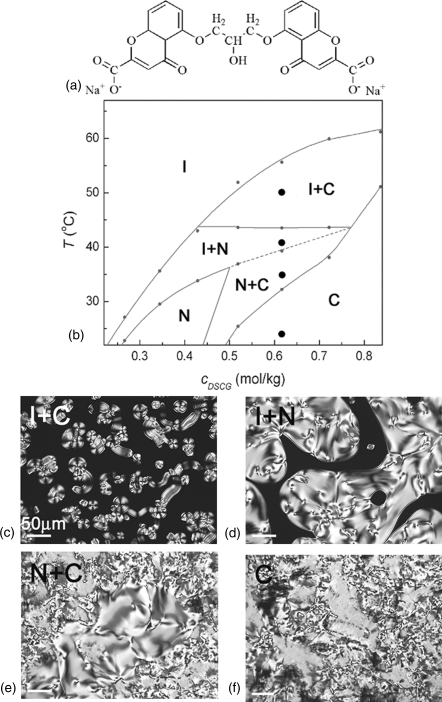
Figure 14.4 shows the phase diagram of pure DSCG water solution [53]. At room temperature (23°C), as the concentration of DSCG increases, the aqueous solution of DSCG shows the I phase at cDSCG < 0.22 mol/kg (10 wt.%) followed by a biphasic state of coexisting N and I phases, N phase, coexisting N and C phases, and a homogeneous C phase at cDSCG > 0.52 mol/kg (21 wt.%). We note that highly concentrated DSCG solutions show a phase transition sequence with increasing temperature that is different from the case of SSY solutions. For example, 0.62 mol/kg of DSCG, being in the homogeneous C phase at room temperature, transforms into the N + C biphasic state, then the I + N biphasic state, and then the I + C biphasic state as the temperature increases, Figure 14.4. In SSY, the phase diagram is much simpler and the homogeneous C phase transforms into less ordered N + C, N, and I + N states upon heating, Figure 14.2.
Figure 14.4 The molecular structure of DSCG (a). Phase diagram (b) and polarizing micrographs (c)–(f) of DSCG water solutions; I + C biphasic state (c), I + N biphasic state (d), N + C biphasic state (e), and C phase (f). The filled circles at the vertical line indicate the temperatures at which the pictures were taken.
14.2.2.1 X-Ray Diffraction Measurement of DSCG Water Solutions
The X-ray diffraction patterns of a DSCG solution are similar to those from SSY solution. The X-ray diffraction pattern for a cDSCG = 0.344 mol/kg (15 wt.%) N sample in the magnetic field directed horizontally shows two pairs of arcs, Figure 14.5(a) [53]. One pair of arcs centered along the vertical axis corresponds to the stacking repeat distance (az = 0.34 nm) between the DSCG molecules in the aggregate. Another pair of arcs centered along the horizontal axis is related to the average distance between the DSCG aggregates. The X-ray diffraction patterns of the C phase of DSCG is similar to the C phase of SSY, showing a strong sharp diffraction line at the small angle 2θ ≈ 1.1 ~ 1.5° and three faint diffraction lines, which arise from the long-range hexagonal packing of the columns in the plane perpendicular to ![]() . The inter-aggregate axis-to-axis distance D decreases as cDSCG increases, Table 14.2. The stacking distance az = 0.34 nm is not changed, but ξL,DSCG is larger than that in the N phase, Table 14.2.
. The inter-aggregate axis-to-axis distance D decreases as cDSCG increases, Table 14.2. The stacking distance az = 0.34 nm is not changed, but ξL,DSCG is larger than that in the N phase, Table 14.2.
Figure 14.5 X-ray patterns of DSCG water solutions; (a) N phase, DSCG c = 0.34 mol/kg; (b) C phase, DSCG c = 0.96 mol/kg. The arrow in (a) represents the direction of the magnetic field. (c) Diffractographs of DSCG water solutions at different concentrations of DSCG: 0.34 mol/kg, 0.62 mol/kg, and 0.96 mol/kg. All data are taken at 28.4°C. (Reprinted with permission from Park [53].)
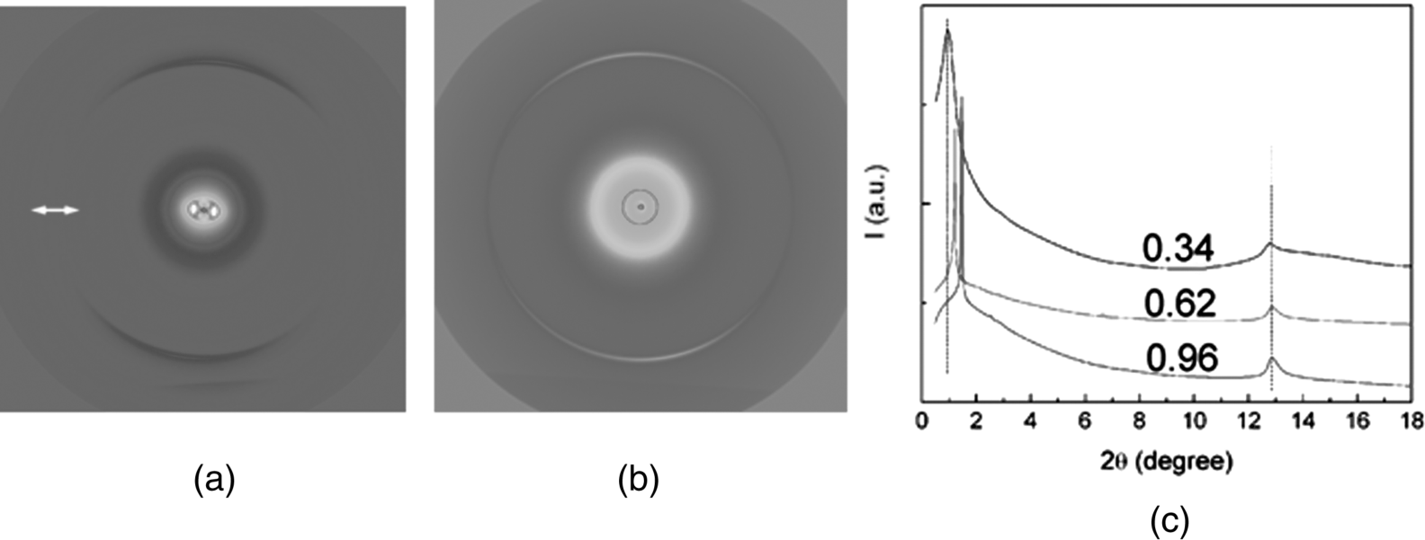
Table 14.2 X-ray diffraction data for four different concentrations of DSCG in water, expressed in molal cDSCG (mol/kg) and volume fraction ϕDSCG units. The temperature is fixed at 28.4°C.

14.2.3 Effects of Molecular Structure on Phase Diagrams of LCLCs
The molecular structure–property relationships of LCLCs present an interesting question, but they are not clearly understood because most of the studies of LCLCs have been performed on a few available materials. Recently, Tam-Chang and coworkers synthesized several derivatives of rylenebis(dicarboximide) dye and described the effect of the structures of the counterions, side chains, and core ring systems on the LC properties of these compounds, Figure 14.6 [13, 30, 54]. They demonstrated that replacing the side-chain, CH2CH2NH(CH3)2, in a perylenebis(dicarboximide), dye (a) in Figure 14.6, with a bulky alkyl chain, CH2CMe2CH2NH(CH3)2, dye (b) in Figure 14.6, destabilizes the N phase by lowering the transition temperatures TN→N+I and TN+I→I [13, 30]. They also showed that replacing the chloride ions by tosylate ions, dye (c) in Figure 14.6, formed the I + C biphase at high concentration instead of homogeneous N or C phases [30]. The effect of the aromatic ring structures was investigated by comparing the properties of perylenebis(dicarboximide), dye (a) in Figure 14.6 and quaterrylenebis(dicarboximide), dye (d) in Figure 14.6 [13, 30]. Dye (d) in Figure 14.6 was only soluble in acidic solutions, such as HCOOH or H2SO4 aqueous solution, but not in water. The maximum of absorption peak, λmax, of dye (d) in Figure 14.6, is red-shift by ~300 nm compared to λmax of dye (a) in Figure 14.6, as a result of a more extended molecular core.
Figure 14.6 (a)–(e) Molecularly designed rylenebis(dicarboximide) dyes prepared by Tam-Chang et al. [13, 30, 54].
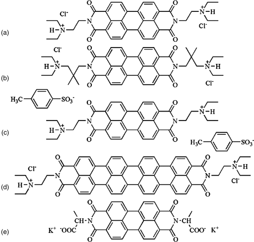
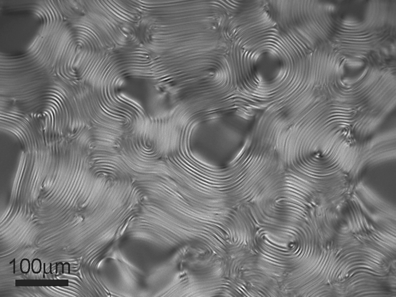
The introduction of a chiral center in a side-chain results in a cholesteric phase, as evidenced by the characteristic fingerprint texture associated with a helical twist of the director, dye (e) in Figure 14.6 [54]. A cholesteric phase can also be attained by adding an amino acid with a chiral center such as alanine and glucose, to the N phase LCLCs [9]. Figure 14.7 shows a micrograph of cholesteric phase formed in 14 wt.% DSCG solution doped with 10 wt.% l-alanine.
Figure 14.7 Polarizing micrograph of cholesteric phase formed in 14 wt.% DSCG solution doped with 10 wt.% l-alanine. The texture shows fingerprint regions with helical axis in the plane of the cell.
14.2.4 Effect of Additives on Phase Diagrams of LCLCs
Aggregation and the subsequent self-assembly of LCLC molecules into the N and C phases depend on a number of factors. (a) The intra-aggregate interactions responsible for the monomer stacking and reversible aggregation are determined mainly by non-covalent attractive forces such as π–π interaction and repulsive electrostatic forces between the ionized groups, such as sulfonate and carboxylate. The extent of ionization of these groups depends on the pH of the solution. (b) The inter-aggregate interactions are mainly controlled by the excluded volume effects, as in the Onsager model of nematic order [47]; electrostatic forces, usually of a repulsive nature; and repulsive hydration forces (i.e., forces derived from the work needed to dehydrate the hydrophilic lateral surfaces of the aggregates [55, 56]). Several previous studies have demonstrated how the phases of LCLCs are affected by additives, either charged, such as salts [8, 19, 26–29], or non-charged, such as neutral polymers [29, 51, 57, 58].
14.2.4.1 Ionic Additive Effect on LCLCs
Exploration of the electrostatic effects started with the observation made by Yu and Saupe [8] that the addition of a salt NaCl to DSCG solution, increases the temperature TN→N+I at which the homogeneous N phase transforms into the biphasic N–I coexistence region, as well as the temperature TN+I→N of the complete melting. Kostko et al. [26] supported this conclusion of the salt-induced increasing of TN→N+I and TN+I→I for the case of salts with small cations, Na+, K+, but also found an opposite effect of destabilization of the N phase by salts with large organic cations, such as tetraethylammonium bromide and tetrabutylammonium bromide. A study by Prasad et al. [27] showed that NaCl increases the viscosity of SSY solution, but did not find any change in the transition temperatures.
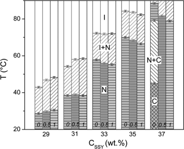
Recently, Park et al. [29] explained a strong effect of a monovalent salt NaCl on phase diagrams that is different for high and low concentrations of SSY, Figure 14.8. The salt promotes the orientational order at low concentrations of SSY and suppresses it at high concentrations; the later behavior is in agreement with the earlier studies of the Tiddy and co-workers [28]. Moreover, in highly concentrated SSY solutions, the salt is capable of melting the positionally ordered C phase into the positionally disordered N phase. Park et al. [29] suggested that these experimental findings are caused by the salt-induced screening of electrostatic repulsion among the charged SSY molecules within and between the aggregates. The screening leads to (1) increase of the scission energy and elongation of aggregates and (2) decrease of their persistence length. The two tendencies (1) and (2) have an opposite effect on the ordered phases, as (1) promotes the stability of the N and C orders, while (2) suppresses both orientational and positional orders.
Figure 14.8 Phase behavior of SSY solution in the presence of NaCl, 0; 0.5; and 1 mol/kg. The transition temperatures were determined upon cooling [29].
14.2.4.2 Nonionic Additive Effect on LCLCs
Recently, several studies showed that the effects of the neutral non-adsorbing polymer on LCLCs. Simon et al. [57] demonstrated that some water-soluble polymers added to isotropic DSCG solutions cause the formation of birefringent droplets. Tortora et al. [51, 58] showed that polyethylene glycol (PEG) can condense DSCG solutions into orientationally and positionally ordered domains of various morphologies, such as tactoids of the N phase, and toroids of the C phase. In the condensed region, the LCLC director was shown to be tangential to the I–N and I–C interfaces.
In the classic picture, the excluded volume effects are considered for colloidal dispersions of particles with a fixed shape, say, rigid rods of constant length and diameter. In this picture, an added depletion agent, such as neutral spheres, forces the rods to pack more closely, as the spheres, and rods cannot penetrate each other. The volume available for both species is maximized when these two are spatially separated [59, 60]. One of the most efficient depletion agents is the neutral non-adsorbing polymer PEG. In water, a PEG molecule behaves as a random coil that can be approximated by a sphere of a certain radius of gyration rg. PEG-induced “depletion attraction” has been observed for a variety of systems, including the solutions of DNA [61–64].
Park et al. [29] demonstrated that PEG added to the isotropic or nematic solutions of SSY causes a strong condensing effect on SSY, triggering phase separation and condensation of the LC phases, either of the N type or the C type, Figure 14.9. The role of PEG is primarily in condensing the SSY into more densely packed regions with a higher concentration of SSY in which the system can acquire an orientational order (forming the N phase from the original I phase) or even a positional order (forming the C phase). Since the main structural unit of LCLC is a self-assembled aggregate rather than an individual molecule, the excluded volume effects are expected to occur at two different levels: for dilute system with short aggregates, the effect is mostly in the increase of the aggregate length, while for the longer aggregates in more concentrated solutions, the effect is in a denser lateral packing with an ensuing orientational and positional order, Figure 14.10. PEG also decreases the inter-aggregate separation in the condensed regions [29].
Figure 14.9 The ternary phase diagram (a) and polarizing micrographs of SSY and PEG water mixtures; N phase (b), I + N phase (c), I + N + C phase (d), and I + C phase (e). See Ref. [29] for more details.
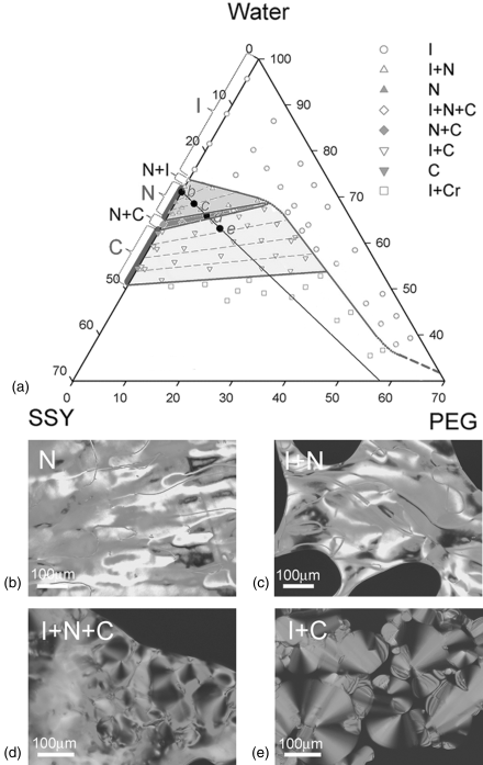
Figure 14.10 Schematic illustration of the excluded volume effect of the increasing concentration of PEG and chromonics: elongation of short aggregates (a), followed by parallel arrangement in the N phase (b) and C phase (c).

14.2.4.3 pH Effect on LCLCs
The ionic groups of chromonic molecules, such as sulfonate and carboxylate groups, play an important role in water solubility as they are easily ionized in the broad range of pH. For example, at the neutral pH, SSY in water is negatively charged with the molecular charge ~2e, caused by the ionization of two sulfonate groups. However, at a high pH, SSY molecules increase their negative charge as a result of the additional ionization of either OH or NH groups in the central part of the molecules [65–67]. Using the values of the acid dissociation constants pKa = 10.4 from Ref. [67], one can estimate the relative population of two species, the −3 charged form and the −2 charged form, in water solutions as a function of pH. At the neutral pH (in the range between ~5 and 8), most of SSY molecules exist in the −2 charged form. As pH increases, SSY becomes more charged; above pH = 12.4, more than 99% of SSY molecules have a charge −3. The high negative charge of SSY at high pH weakens aggregation, decreasing the scission energy E, see Eq. (14.1). A study by Gooding et al. [66] showed that the aggregation of SSY in dilute solutions (cSSY < 0.1 mol/kg) and found that at pH ≥ 13, SSY does not aggregate at all.
Taylor and Herzfeld [68] demonstrated that when E decreases, the N phase disappears, giving rise to the coexisting I + C phases. At a very low E, the system might even crystallize. All these predictions are in qualitative agreement with the experimental results [19]. Namely, at low concentrations cNaOH of the added base NaOH, the increased pH narrows the temperature range of the N phase. At higher cNaOH, the base promotes biphasic regions I + N, I + C, and then a complete isotropization of the solution with precipitation of a crystalline phase, Figure 14.11.
Figure 14.11 Polarizing micrographs for c = 1.14 mol/kg SSY solution doped with NaOH at different concentrations: (a) cNaOH = 0 mol/kg, pH = 6.5, homogeneous N phase; (b) cNaOH = 0.1 mol/kg, pH = 11.6, coexisting N and I phases; (c) cNaOH = 0.2 mol/kg, pH = 11.9, coexisting C and I phases; (d) cNaOH = 0.5 mol/kg, pH = 12.5, homogeneous I phase; (e) cNaOH = 2 mol/kg, pH = 13.2, precipitate.

14.3 Emerging Applications of LCLCs
Chromonic molecules are self-assembled through noncovalent thus relatively weak interactions, such as π–π attraction into the ordered structures, which depends on many factors such as ionic content, pH, temperature, concentration, and molecular structures. They can be used for the control of supramolecular entities in LCLCs to generate functional materials and devices. Here, we summarize the recent development of the potential applications of LCLCs. Two primary areas of applications are presented: anisotropic dried films formed from the aligned LCLC precursors by evaporating water and LCLCs in their fully hydrated bulk state.
14.3.1 Applications of LCLCs in the Form of Dry Films
The first relatively well-studied application of LCLCs is the fabrication of the highly ordered thin films with anisotropic properties for optical elements [13, 31, 69–75], such as linear polarizers, retarders, security tags, and optical compensators. All these applications take advantage of the fact that the structure of chromonic materials in the LC state is orientationally ordered. As a result, the LCLCs show useful structural and optical properties, such as birefringence and polarization-dependent absorption.
The planar alignment of LCLCs with aggregates parallel to one particular direction in the plane of substrate can be achieved by mechanical shearing [12, 31], or by a specially treated alignment layer [18]. Once the aligned structure of LCLCs is created in the LC state, it can be “frozen” by evaporating the solvent. The resulting dry film still preserves an orientational order and, thus, anisotropic optical properties. Preserved in-plane long-range orientational order has been demonstrated not only for micron-thick films but also for nano-thick films prepared by a layer-by-layer electrostatic deposition and composed of one or few stacked LCLC monolayers [12, 35]. Note that the N and C phases in contact with their own isotropic melt, align the director in the plane of the interface (tangential orientation) [29, 51, 58].
An alternative homeotropic alignment of LCLCs with aggregates being perpendicular to the substrates is much harder to achieve. So far, there is only one reported technique for water-based LCLCs, based on glass plates treated with weak water solutions of N,N-dimethyl-N-octadecyl-3-aminopropyl-trimethoxysilyl chloride (DMOAP) [52]. A study by Tolkki et al. [76] showed that an LCLC formed with organic solvents can be aligned homeotropically on a layer of fullerene C60.
To the best of our knowledge, there are no reports on the tilted alignment of LCLCs, except an observation that such an alignment can be achieved in very small domains of the LCLCs surrounded by the I phase [29]. This might be related with the fact that the tilted alignment is not compatible with the aggregated nature of building units.
14.3.1.1 Polarizers
The conventional dichroic polarizers are used as external polarizers for LCDs, which are usually assembled with glass substrates. The display market demands flexible, light-weight, unbreakable, and cheap displays. The plastic substrate is a solution to meet these demands; however, most plastics are birefringent, which leads to serious shortcomings when the external polarizers are used. The oriented LCLC film can be used as internal polarizers because of their anisotropic absorption. The chromonic internal polarizers, thus, allow one to use inexpensive birefringent easy-to-process plastics for the development of flexible LCDs.
The first claim of the LCLC-based polarizer was made by Dreyer [69, 70]. An orientationally ordered film can be prepared using a suitably treated (rubbed) surface or by applying an external field. Crowley et al. [77] showed the shear-induced alignment of azo dye, CI acid red 266 and cyanine dye. Shear-induced alignment is an easy and useful technique for aligning chromonic LCs. A study by Iverson and Tam-Chang [78] showed that shear-induced orientation of the synthesized rylenebis(dicarboximide) dye followed by evaporation of solvent led to polarizing films with dichroic ratio as high as 30. Sergan et al. [31] built the twisted nematic (TN) LCD with plastic substrates and chromonic internal polarizing layers which provided the contrast ratio of at least 70:1. They also demonstrated that the chromonic dye films can provide uniform planar alignment for rod-like thermotropic LCs, Figure 14.12. The chromonic polarizing films are effective over the range of absorption wavelength of the particular chromonic dyes, which is related with the structure of molecule; see the previous section. Using these properties, Tam-Chang et al. [13] showed that a synthesized chromonic dye with a large conjugated aromatic core, such as quaterrylenebis(dicarboximide) can be used for near-IR polarizing materials. Tam-Chang et al. [13] demonstrated that a broad spectrum polarizing film can be made by using a mixture of molecularly designed chromonic dyes which absorbs over almost the entire visible range.
Figure 14.12 Schematic illustration of alignment of thermotropic LC molecules on chromonic dye layer.
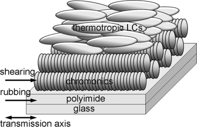
One of the major problems for practical uses is that the dry chromonic films develop undesirable periodic stripe patterns that are often called “tiger stripes” or “herringbone textures” because of their characteristic textures under the polarizing microscope. X-ray microscopy and near edge X-ray spectra (NEXAFS) spectroscopy of texture formation in dry chromonic films revealed that these periodic patterns are formed by nearly sinusoidal or in some cases zig–zag undulations of the chromonic columns [50]. Kaznatcheev et al. [50] proposed that the undulations and the related “tiger stripes” and “herringbone” textures are caused by the decrease of the inter-columnar separation upon evaporation of water. When the separation between the columns decreases, they need to form a periodic tilted structure to fill the space available, as the effective separation between the tilted aggregates is larger than a separation measured along the normal to the aggregates. The effect is similar to the well-known Helfrich–Hurault effect in smectic LCs, see, for example [45].
Schneider et al. [34] demonstrated that the stripe textures can be eliminated by adding a certain block copolymer to the LCLC formulation, which dramatically improves the polarizing efficiency of the films. The exact mechanisms behind this empirical recipe will remain unclear until we learn much more about the viscoelasticity of LCLCs. A study by Yaroshchuk et al. [79] showed that the ion/plasma beam treatment of polyimide-covered substrates significantly improves the alignment of LCLCs in the form of fully hydrated mesomorphic solutions and in the form of dry films.
Recently, Bae et al. [80] demonstrated a technique to prepare thin polarizing films using non-aqueous LCLCs. They prepared a photocurable organic solution of red-colored chromonic dye, bis-(N,N-diethylaminoethyl)perylene-3,4,9,10-tetracarboxylic diimide in a photo-polymerizable solution composed with acrylic acid and small amount of photoinitiator with a multifunctional monomer (pentaerythritol tetraacrylate). The solution was in the N phase. They coated this photocurable LCLC organic solution onto a glass or plastic substrate with mechanical shearing and then irradiated with UV light for polymerization. This polymerized polarizing film from an organic-based LCLC solution showed better surface hardness, adhesion to substrates, and solvent resistance than the polarizing films form aqueous LCLCs. Park et al. [81] also described that the polymer-stabilized chromonic thin film shows good mechanical stability and chemical stability. They prepared the N phase solution of chromonic dye, water, and acrylic acid and then coated this solution onto the substrates. After evaporation of water, they polymerized thin film by UV irradiation.
14.3.1.2 Layer-by-Layer Deposition of LCLCs
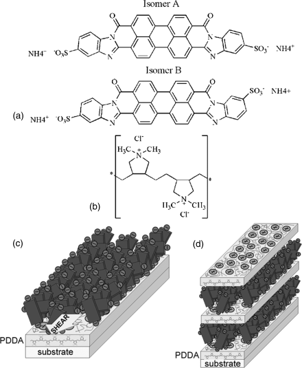
A different technique to prepare in-plane oriented molecular mono- and multi-layered films of chromonic materials with nanometer thickness is the electrostatic layer-by-layer deposition of the LCLCs and polycations [12, 35, 82]. A glass or mica substrate was modified with a polycation, poly(diallyldimethyammonium chloride) (PDDA) and then the N phase of chromonic solution, Violet 20 (V20), was deposited onto the PDDA layer with mechanical shearing. The excess of LCLCs was rinsed off to produce the chromonic monolayer [12]. Using atomic force microscopy and X-ray photoelectron spectroscopy, Schneider et al. [35] demonstrated that the orientationally ordered chromonic aggregates are preserved within the monolayer of a dry LCLC film with aggregates aligned parallel to the substrate, Figure 14.13.
Figure 14.13 Molecular structure of violet 20 (a) and PDDA (b). Schematic diagrams showing the plausible geometry of (c) monolayer of chromonics onto the layer of PDDA and (d) multilayered structure of PDDA/chromonics. (Redrawn from Schneider and Lavrentovich [12] and Schneider et al. [35].)
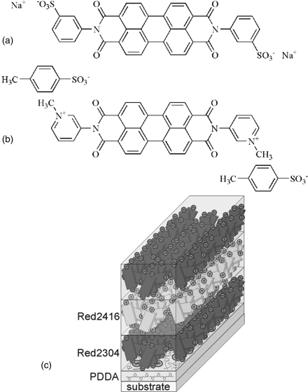
Using the electrostatic layer-by-layer deposition technique, Boiko et al. [82] reported the film comprised alternative layers of positively and negatively charged chromonic LCs, Figure 14.14.
Figure 14.14 Molecular structure of negatively charged dye Red 2304 (a) and positively charged dye Red 2416 (b), and (c) schematic diagram of the multilayer structure of PDDA/Red 2304/Red 2416. (Redrawn from Boiko et al. [82].)
14.3.1.3 Micro-Patterned Chromonic Films
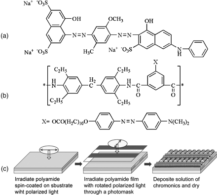
One of the versatile approaches for aligning LCLCs is the use of orienting surfaces made from photo-aligned polymer films [72, 83–87]. Compared with other aligning techniques, this technique has an advantage of producing multiple orientations of LCLCs on a single film. Photoalignment using photoisomerizable molecules such as azobenzene is based on their anisotropic reorientation produced by the polarized light irradiation. The orientational order of azobenzene compounds can be effectively transferred to the photochemically inactive LCLCs, such as DSCG [72] and C.I. Direct Blue 67 [83, 84]. Matsunnaga et al. [85] demonstrated that micropatterns of chromonic materials can be fabricated using this photoalignment technique. They spin-coated a polyamide with a photoresponsive dimethylaminoazobenze (MNC10-PAM) on a glass substrate, irradiated the polyamide film with linearly polarized light, and then irradiated again with 90° rotated linearly polarized light through a photomask to reorient azobenzene components in the exposed regions. An aqueous solution of 5 wt.% of C.I. Direct Blue 67 was applied on the photo-aligned layer and then dried to produce a micro-patterned film, Figure 14.15.
Figure 14.15 The molecular structure of C.I. Drirect Blue 67 (a) and polyamide with a photoresponsive dimethylaminoazobenze (MNC10-PAM) (b). Schematic diagram illustrating the procedure for fabricating micro-patterned polarizing films (c). (Redrawn from Matsunaga et al. [85].)
Another approach to generate micro-patterned chromonic elements is to use the micro-patterned template. A study by Tam-Chang et al. [38] showed the fabrication of micro-patterns of anisotropic materials using a template with micro-scaled line features. An isotropic solution of a synthesized perylenebis(dicarboximide) was introduced between a cover glass slide and polydimethylsiloxane (PDMS) template with regular line features of ~9 μm wide, ~2 μm deep, and ~11 μm apart. The chromonic solution became more concentrated into the LC phase by slow evaporation of solvent. After the sample was dried, the PDMS template was peeled off, leaving an array of parallel stripes of aligned dry chmononics, Figure 14.16.
Figure 14.16 Schematic diagram illustrating the template-guided organization of LCLCs leading to a micropattern of anisotropically ordered solid. (Redrawn from Tam-Chang et al. [38].)

Nastishin et al. [88] reported a photo-induced alignment of the LCLCs by polarized light acting directly on the LCLC slab rather through the effects in the aligning substrates. In the experiment, a uniform planar texture of an LCLC was shown to realign by as much as 90° under irradiation with a linearly polarized laser beam. The effect was observed for LCLC materials, such as dye Blue 27 that absorbs light. For transparent LCLCs, such as DSCG, the photo-induced realignment is not observed, but once the material is doped with a light absorbing agent, the LCLC acquires the ability to realign in the polarized light.
14.3.1.4 Organic Electronics
The field of organic electronics has gained considerable attention because of the emerging applications in flexible displays and electronics such as light-emitting-diodes (LEDs), photovoltaic cells, and filed effect transistors (FETs). Among the various conductive organic materials, LCs are currently viewed as an attractive candidate for organic electronics because of their long-range orientational order and adaptive structure that heal local defects [89–92]. Recently, several studies showed the electro-optical properties of π-stacked LCLCs [41, 76, 93]. LCLCs are good for processing devices since the orientational order of LCLCs with dense packing is preserved when the aggregates are transferred from the LC solution into thin films by drying. LCLCs can adopt two characteristic orientations required for electronic devices; the planar alignment which is needed for FET to ensure the charge migration between the source and the drain, and the homeotropic alignment which is beneficial for the performance in LED or photovoltaic cell.
Nazarenko et al. [41] demonstrated that aligned dry films of LCLCs exhibit semiconducting properties with anisotropic mobility of charge carries caused by the directional π–π interactions. They deposited LCLCs on the glass substrates either parallel or perpendicular to the gap of two gold electrodes separated by 15 μm and determined the charge carrier mobilities, μ![]() = 5 × 10⁻³ cm2 V−1 s−1 and μ⊥ = 3 × 10⁻⁵ cm2 V−1 s−1, Figure 14.17(a) and (b). The electronic delocalization in two dimensions is a characteristic feature of LCLCs, which is not observed in linear conductive polymers. The electric properties of LCLCs depend strongly upon their aggregate structure and the orientation of aggregates on the substrate.
= 5 × 10⁻³ cm2 V−1 s−1 and μ⊥ = 3 × 10⁻⁵ cm2 V−1 s−1, Figure 14.17(a) and (b). The electronic delocalization in two dimensions is a characteristic feature of LCLCs, which is not observed in linear conductive polymers. The electric properties of LCLCs depend strongly upon their aggregate structure and the orientation of aggregates on the substrate.
Figure 14.17 Schematic diagrams of FET; LCLC aggregates aligned parallel (a) and perpendicular (b) to the gap of two gold electrodes, source and drain, on a gate substrate. (Redrawn from Nazarenko et al. [41].)

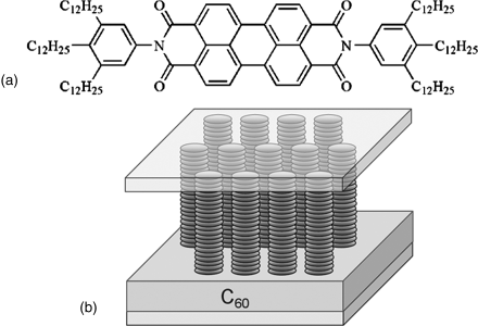
A study by Tolkki et al. [76] showed that the aggregation of chromonic dye, N,N-di(3,4,5-tridodecylphenyl)-perylene-3,4,9,10-tetracarboxylic acid diimide (PDI12) exhibits the long fluorescence lifetime, ~40 ns, in both solution and thin dry film. They prepared the double-layer system with homeotropic aligned PDI12 layer on top of layer of fullerene C60 and presented fluorescence quenching and photo-induced voltage caused by the interaction between PDI12 and C60, Figure 14.18. The homeotropic aligned PDI12 film with the thickness of 10 nm was prepared by the Langmuir–Schaeffer method. They explained that chromonic dye PDI12 acts as an electron acceptor and C60 as an electron donor showing promising photoelectric properties.
Figure 14.18 Molecular structure of PDI12 (a) and schematic diagram (b) of the double-layer system with homeotropic aligned PDI12 layer on top of layer of C60. (Redrawn from Tolkki et al. [76].)
14.3.1.5 Vertically Aligned Graphene Layers Prepared by LCLCs
Graphene, a plat monolayer of carbon atoms tightly packed into a two-dimensional honeycomb lattice, has been attracting much attention owing to its fascinating physical properties, such as quantum electronic transport, tunable band gap, extremely high mobility, and high elasticity [94–97]. Since the discovery of the first isolated graphene prepared by mechanical exfoliation of graphite crystals, many chemical approaches to synthesize graphene have been developed. Graphene monolayers typically deposit themselves flat on substrates or associate face-to-face to form stacked multilayers parallel to the substrates.
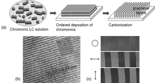
Recently, Guo et al. [40] demonstrated that LCLCs can be used to fabricate vertically aligned graphene layer arrays (VAGLAs) with heights from 50 to 800 nm and with two-dimensional in-plane orientational order. Several different sulfonated chromonic dye solutions (such as Blue 27, Violet 20, and Bordeaux dye) were applied on substrates by mechanical shearing. The chromonic films were then dried at room temperature and carbonized by directly heating in nitrogen at 700°C. It was suggested that during the carbonization process, the orientation of the disk-like molecules on substrates becomes stabilized through edge-to-edge polymerization reactions, in which neighboring molecular disks cross-link and merge into vertical graphene layers, Figure 14.19. They also demonstrated that the local shear force can be used to make polarization-active patterns or imbedded lettering apparent only under polarized light, Figure 14.19 [40].
Figure 14.19 Schematic diagram illustrating the formation of vertically aligned graphene layer arrays (a). HR-TEM image showing the full fringe field in Z-axis projection, indicating vertical graphene layer orientation (b). An optically imbedded VAGLAs pattern on quartz (25 × 75 mm) with two orthogonal directions by the microshear technique (c). The arrow indicates the polarization direction of light and the circle indicates unpolarized light. (Reprinted with permission from Guo et al. [40].) (See the color version of this figure in Color Plates section.)
14.3.2 Applications of LCLCs in the Form of Aqueous Solutions
14.3.2.1 Biosensor
Anisotropic optical properties of LCLCs such as birefringence can be used for enhancing optical images for biosensors. LCLCs are not toxic to many microbial species [98] and antibody–antigen binding is not altered by LCLCs [99], which are also important conditions for using them in biological sensing. Lavrentovich and coworkers explored the use of LCLCs in biosensors [36, 37, 98, 100]. They filled a mixture of the N phase DSCG, antigen-coated (streptavidin) microbe (latex beads of diameter ~0.6 μm), and corresponding antibody (anti-streptavidin) into a cell consisted of two glass plates coated with rubbed polyimide for a planar alignment of DSCG aggregates, Figure 14.20.
Figure 14.20 The scheme of the LCLC biosensor for the detection of immune complexs. (Redrawn from Shiyanovskii et al. [37].) (See the color version of this figure in Color Plates section.)
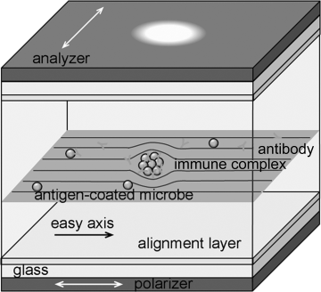
The idea of LCLC-based detection is as follows. Each microbe has characteristic molecular groups-antigens at the surface, to which a corresponding antibody can bind, thus “recognizing” and “detecting” it. Each antibody molecule has two binding sites; thus this binding often results in the formation of an aggregate of microbes, namely, an immune complex. A director distortion of LCLCs is used to amplify the recognition and detection of immune complex. If such a complex grows in the LCLC bulk and becomes larger than some critical size dc ~ K/W ~ 1 μm, then it should cause director distortions and optical distinction by placing the sample between two crossed polarizers. Here K is the typical Frank elastic constant and W is the polar anchoring coefficient at the LC–particle interface [36, 37].
The biological selectivity of detection is guaranteed by the selectivity of antibody–antigen binding. Helfinstine et al. [100] also used this scheme for detecting Bacillus atrophaeus (BA) spore by anti-BA endospore antibody. The biosensor would function in real time to determine the formation of immune complexes since the director distortion at length scales (0.1–10 μm) occur faster than 0.1 s [37].
14.3.2.2 Optical Compensators
It is known that the twisted nematic (TN) LCD has a problem of narrow viewing angle. Light leakage in the dark state and uneven retardation change along the viewing angle cause the asymmetric distribution of light intensity in gray scale. One of the most successful ways to solve this intrinsic problem is to use the optical compensation films. Polymer films with negative birefringence are usually used to counteract the positive birefringence of the nematic LC cells.
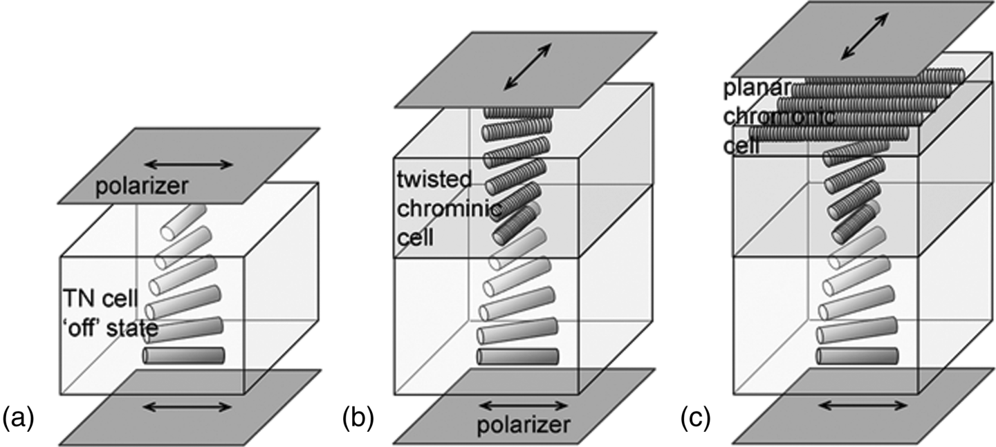
There are two geometries in TN LCD with two polarizers placed either parallel (‘normally black’ or NB mode) or perpendicular (‘normally white’ or NW mode) to each other. The NB mode is in the dark state when the LC director undergoes a 90° twist between two paralleled polarizers. The NW mode shows dark state when the applied field transforms the LC director from 90° twisted state to a homeotropic state between the crossed polarizers. Lavrentovich et al. [73, 74] demonstrated that the N phase LCLC cells can be used as compensating plates in TN LCD. To match the twist director of the cell in the dark state in the NB mode, they used the twisted chromonic LC cell doped with l-alanine (see previous section) or the combination of the twisted chromonic cell and planar chromonic cell, Figure 14.21. The compensating chromonic cells provide achromatic dark sate and contrast ratio up to 50:1 at all directions within a 40° come of viewing angle [73].
Figure 14.21 The configuration of a NB mode of TN LCD: (a) a uncompensated TN cell; (b) a TN cell compensated with a twisted N* phase chromonic cell; (c) a TN cell compensated with a twisted N* phase cell and a planar chromonic cell. (Redrawn from Lavrentovich et al. [73].)
In the dark state of the NW mode TN cell shows the homeotropic director configuration in the middle of the cell, but it shows the splay deformed director configuration near the bounding plates. To compensate the dark state of the NW mode of TN LCD, the uniaxial planar chromonic cell can be used together with a discotic nematic film with negative birefringence and splay optic axis configuration developed by Fuji photo film, Figure 14.22, [73]. Sergan and Kelly [33] also demonstrated that chromonic dry film can be used for compensation of the dark state of the TN LCD combined with commercially available optical retarders. The range of retardation can be easily controlled by the film thickness and concentration of the chromonic solution.
Figure 14.22 The configuration of a NW mode of TN LCD: (a) a uncompensated NW TN cell; (b) a NW TN cell compensated with a negative birefringence discotic nematic film and a planar chromonic cell with optic axis in the plane of the film (negative A-plate). (Redrawn from Lavrentovich et al. [73].)

14.3.2.3 Functional Material for Nano-Fabrications
Metal nanorods (NRs) show potential for numerous practical applications ranging from molecular [101] and biological sensors [102] to solar energy conversion [103] and the construction of optical cloaking devices [104–106]. One of the most challenges of nanotechnology today is to develop simple and reliable techniques to produce the complex arrangements and assemblies of NRs which are the key to the successful application of the nanoparticle-based devices. The assemblies of metallic NRs show dramatic modification of their optical and electric properties as compared to those of individual NRs [107, 108] and consequently can be used as the “building units” for more complex architectures.
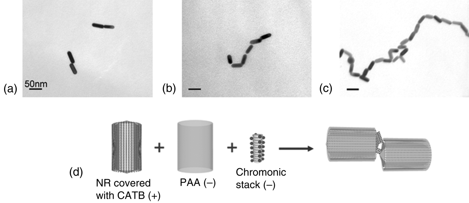
Recently, Park et al. [39] described a technique for assembling metallic NRs utilizing the anisotropic attractive forces between the NRs and aggregated stacks of chromonic materials. They used DSCG aggregates, as the linking agent for NR assembly. As described above, DSCG molecules stack face-to-face, leaving the charged groups, carboxylate, at the aggregate–water interface with counterions, Na+. The stacks thus represent self-assembled macroions with the ability to interact with other charged species, such as gold NRs covered with ionic surfactants, hexadecyltrimethylammonium bromide (CATB). CTAB is a cationic surfactant that forms a double layer around each gold NR. The anisotropic electrostatic interaction between the chromonic stacks and NRs produces the different geometries of NR assembly by changing the surface charge of NRs, and thus changing the nature of their electrostatic interactions with DSCG stacks. When the positively changed gold NRs are mixed with DSCG solution, the negatively charged DSCG stacks easily attach on the lateral surface of the gold NR producing side-by-side assembled gold NR structures, Figure 14.23. When the isolated gold NRs are coated with poly(acrylic acid) (PAA) to screen the positive charges on the lateral surface, the DSCG stacks effectively bind on the ends of gold NRs producing end-to-end assembled gold NR structures, Figure 14.24. The unique feature of this technique is that the assembly of NRs can be controlled by many parameters since the structure of the linkage agent chromonic stacks is not fixed and depends strongly on temperature, concentration, and pH of the solution. The process of NR assembly can be quenched by the dilution of the solution and by adding a polyelectrolyte to the solution of NRs and DSCGs.
Figure 14.23 Side-by-side assembly of gold NRs induced by 0.8 mM DSCG solution mixed with ~2 nM gold NR solution, in 1:1 ratio. (a) TEM image of the control sample, no DSCG; (b) and (c) assembled structures of gold NRs formed after the addition of DSCG solution. (d) Schematic representation of the side-by-side assembly of positively charged gold NRs mediated by negatively charged stacks of DSCG serving as self-assembled multivalent counter ions. (Redrawn from Park et al. [39].)
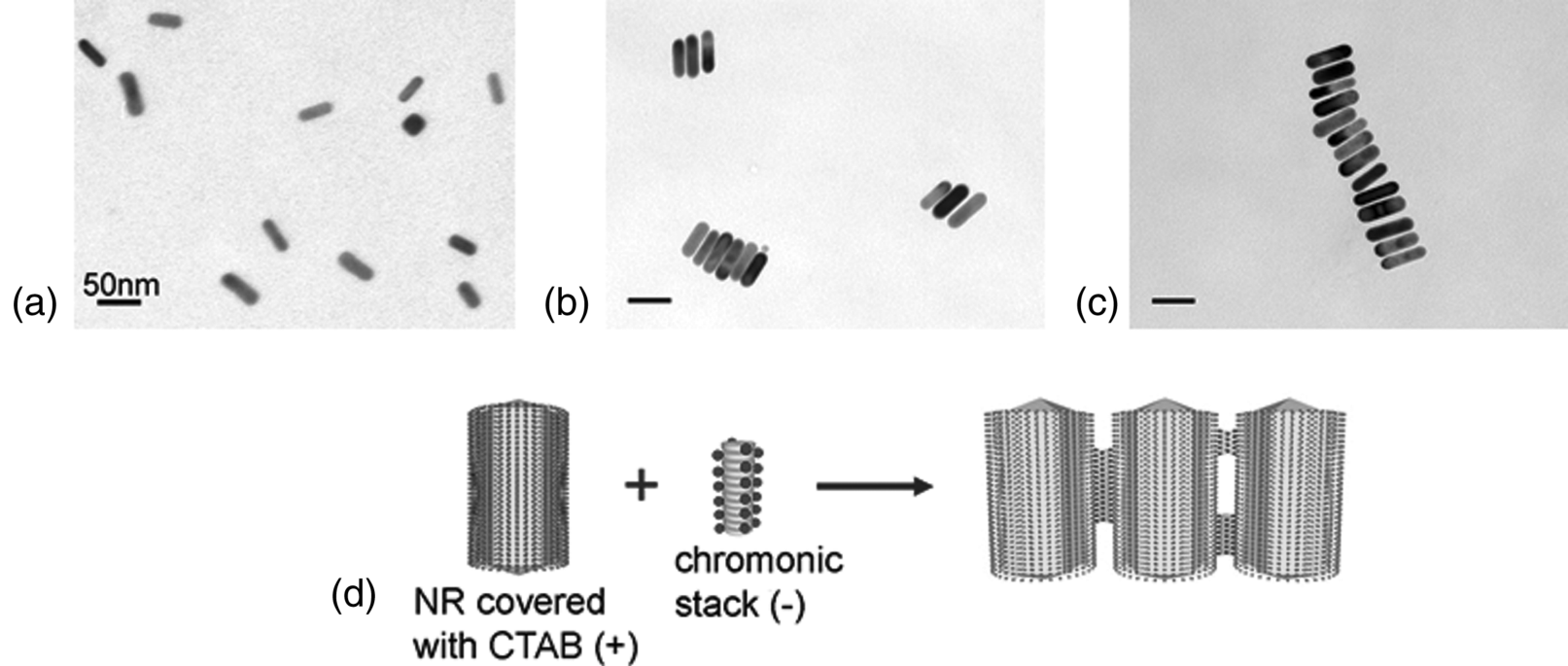
Figure 14.24 End-to-end assembly of Au NRs with CTAB and PAA coating, induced by 0.2 M DSCG added to ~2 nM NR solution in 1:1 ratio. TEM images of the end-to-end chains were taken about 2 h (a), 5 h (b), and 24 h (c) after the mixture preparation. (d) Schematic representation of the end-to-end assembly. (Redrawn from Park et al. [39].)
Park et al. [39] also demonstrated that the LCLC-assisted assembly of gold NRs is reversible, which represents an important improvement as compared to many other known techniques of NRs assembly, such as covalent binding. For example, side-by-side assembled NR structures can be disassembled through the increase of pH. As already indicated, high pH increases the negative charge of the DSCG molecules and leads to shortening of the DSCG stacks, rendering them less capable of linking the NRs [39].
14.3.2.4 Chromonic LCs Formed by Biomolecules
Mundy et al. [109] examined the solution of ethidium bromide (EB) in DSCG water system. EB is a widely used nucleic acid stain which becomes fluorescent when intercalated into DNA. They demonstrated that the pattern of interaction of EB with a DSCG solution is analogous to its interaction with DNA, suggesting that the stacking of bases in DNA can be regarded as being similar to the chromonic stacking.
Recently, Clark and coworkers investigated the mesomorphic behavior of relatively short strands of oligomeric DNA and RNA [110–112]. Nakata et al. [110] found that relatively short complementary B-form DNA oligomers, only 6–20 base pairs in length, are capable to exhibit N and C phases in water solutions. At first sight, such a finding is very surprising, as the duplexes are very short and lack the shape anisotropy needed to establish the orientationally ordered phases. It turned out that the mechanism of mesophase formation is directly related to the chromonic-like stacking of DNA duplexes on top of each other, similar to the H-aggregation of individual chromonic molecules considered above. Further experiments were performed on mixtures of single-stranded and double-stranded oligomers. When the concentrations are large enough, duplex oligomers are phase-separated into LC droplets from an isotropic background rich in single strands. This phase separation is explained by a combination of depletion-type entropic forces, attributable to flexibility mismatch, and energy gained upon stacking [112]. The effects of LCLC condensation by additives such as PEG described above are thus similar to the effects in the systems formed by biomolecules.
Spindler and coworkers showed that guanosine, one of the four DNA nucleotides, can self-assemble into highly ordered columnar structures in aqueous solutions [15, 16]. Four guanosine molecules assemble to form a planar disk-shaped tetramer and then tetramers stack into an elongated aggregate in the same way as other chromonics do. The stacking distance of the disk-shaped tetramer is 0.34 nm, same as the distance of chromonic stacking [16]. They also described that the addition of monovalent salt such as potassium ion can promote the self-assembly of guanosine tetramers, leading to the formation of the LC phase when enough salt is added. These experiments suggest that the chromonic family embraces a wide range of biomaterials.
14.4 Conclusions
Recently, there has been an increasing interest in LCLCs, not only because chromonic materials represent a distinct class of soft matter showing unique properties different from the conventional lyotropic LCs, but also because they have shown promise for new applications, such as the preparation of optically anisotropic films, micro-pattering, biosensing, and functional materials for nano-fabrication, as described above. Deeper understanding of the properties of LCLCs, including details of aggregation, molecular structure–property relationship, role of concentration, temperature, and ionic content is important not only for the basic research but also for the development of new applications. We hope that this review provides a basic understanding of phase behavior and the physical properties of the self-assembled chromonic materials and expands the opportunities for practical applications of LCLCs.
1. T. K. Attwood, J. E. Lydon, and F. Jones. The chromonic phases of dyes. Liq. Cryst. 1986, 1, 499–507.
2. T. K. Attwood, J. E. Lydon, C. Hall, and G. J. T. Tiddy. The distinction between chromonic and amphiphilic lyotropic mesophases. Liq. Cryst. 1990, 7, 657–668.
3. J. E. Lydon. Chromonic liquid crystal phases. Curr. Opin. Colloid Interface Sci. 1998, 3, 458–466.
4. D. J. Edwards, A. P. Ormerod, G. J. T. Tiddy, A. A. Jaber, and A. Mahendrasingham. Aggregation and lyotropic liquid crystal formation of anionic azo dyes for textile fibres. In: Physico-Chemical Principles of Colour Chemistry; Advances in Color Chemistry Series. A. T. Peters and H. S. Freeman,Ed., Springer-Verlag, New York, 1996.
5. J. E. Lydon. Chromonic mesophases. Curr. Opin. Colloid Interface Sci. 2004, 8, 480–489.
6. S.-W. Tam-Chang and L. Huang. Chromonic liquid crystals: properties and applications as functional materials. Chem. Commun. 2008, 1957–1967.
7. J. E. Lydon. Chromonic review. J. Mater. Chem. 2010, 20, 10071–10099.
8. L. J. Yu and A. Saupe. Deuteron resonance of nematic disodium cromoglycate-water systems. Mol. Cryst. Liq. Cryst. 1982, 80, 129–143.
9. H. Lee and M. M. Labes. Lyotropic cholesteric and nematic phases of disodium cromoglycate in magnetic fields. Mol. Cryst. Liq. Cryst. 1982, 84, 137–157.
10. N. H. Hartshorne and G. D. Woodard. Mesomorphism in the system disodium chromoglycae–water. Mol. Cryst. Liq. Cryst. 1973, 23, 343–368.
11. G. J. T. Tiddy, D. L. Mateer, A. P. Ormerod, W. J. Harrison, and D. J. Edwards. Highly ordered aggregates in dilute water–dye systems. Langmuir 1995, 11, 390–393.
12. T. Schneider and O. D. Lavrentovich. Self assembled monolayers and multilayered stacks of lyotropic chromonic liquid crystalline dyes with in-plane orientational order. Langmuir 2000, 16, 5227–5230.
13. S.-W. Tam-Chang, W. Seo, I. K. Iverson, and S. M. Casey. Ionic quaterrylenebis(dicarboximide): a novel mesogen and long-wavelength polarizing material. Angew. Chem. Int. Ed. 2003, 42, 897–900.
14. V. R. Horowitz, L. A. Janowitz, A. L. Modic, P. A. Heiney, and P. J. Collings. Aggregation behavior and chromonic liquid crystal properties of an anionic monoazo dye. Phys. Rev. E 2005, 72, 041710.
15. L. Spindler, I. Drevensek-Olenik, M. Copic, R. Romih, J. Cerar, J. Skerjanc, and P. Mariani. Dynamic light scattering and 31P NMR spectroscopy study of the self-assembly of deoxyguanosine 5′-monophosphate. Eur. Phys. J. E 2002, 7, 95–102.
16. P. Mariani, F. Spinozzi, F. Federiconi, H. Amenitsch, L. Spindler, and I. Drevensek-Olenik. Small angle x-ray scattering analysis of deoxyguanosine 5′-monophosphate self-assembling in solution: nucleation and growth of G-quadruplexes. J. Phys. Chem. B 2009, 113, 7934–7944.
17. D. Goldfarb, Z. Luz, N. Spielberg, and H. Zimmermann. Structural and orientational characteristics of the disodium cromoglycate–water mesophases by deuterium NMR and x-ray diffraction. Mol. Cryst. Liq. Cryst. 1985, 126, 225–246.
18. Y. A. Nastishin, H. Liu, T. Schneider, V. G. Nazarenko, R. Vasyuta, S. V. Shiyanovskii, and O. D. Lavrentovich. Optical characterization of the nematic lyotropic chromonic liquid crystals: light absorption, birefringence, and scalar order parameter. Phys. Rev. E 2005, 72, 041711.
19. H.-S. Park, S.-W. Kang, L. Tortora, Y. Nastishin, D. Finotello, S. Kumar, S., and O. D. Lavrentovich. Self-assembly of lyotropic chromonic liquid crystal Sunset Yellow and effects of ionic additives. J. Phys. Chem. B 2008, 112, 16307–16319.
20. D. J. Edwards, J. W. Jones, O. Lozman, A. P. Ormerod, M. Sintyureva, and G. J. T. Tiddy. Chromonic liquid crystal formation by Edicol Sunset Yellow. J. Phys. Chem. B 2008, 112, 14628–14636.
21. A. J. Dickinson, N. D. LaRacuente, C. B. Mckitterick, and P. J. Collings. Aggregate structure and free energy changes in chromonic liquid crystals. Mol. Cryst. Liq. Cryst. 2009, 509, 9–20.
22. M. E. Cates and S. J. Candau. Statics and dynamics in worm-like surfactant micelles. J. Phys.: Condens. Matter 1990, 2, 6869–6892.
23. W. M. Gelbart and A. Ben-Shaul. The “new” science of “complex fluids.” J. Phys. Chem. 1996, 100, 13169–13189.
24. L. Joshi, S.-W. Kang, D. M. Agra-Kooijman, and S. Kumar. Concentration, temperature, and pH dependence of sunset-yellow aggregates in aqueous solutions: an X-ray investigation. Phys. Rev. E 2009, 80, 041703.
25. Y. A. Nastishin, H. Liu, S. V. Shiyanovskii, O. D. Lavrentovich, A. F. Kostko, and M. A. Anisimov. Pretransitional fluctuations in the isotropic phase of a lyotropic chromonic liquid crystal. Phys. Rev. E 2004, 70, 051706.
26. A. F. Kostko, B. H. Cipriano, O. A. Pinchuk, L. Ziserman, M. A. Anisimov, D. Danino, and S. R. Raghavan. Salt effects on the phase behavior, structure, and rheology of chromonic liquid crystals. J. Phys. Chem. B 2005, 109, 19126–19133.
27. S. K. Prasad, G. G. Nair, G. Hegd, and V. Jayalakshmi. Evidence of wormlike micellar behavior in chromonic liquid crystals: rheological, X-ray, and dielectric studies. J. Phys. Chem. B 2007, 111, 9741–9746.
28. J. W. Jones, L. Lue, A. P. Ormerod, and G. J. T. Tiddy. The influence of sodium chloride on the self-association and chromonic mesophase formation of Edicol Sunset Yellow. Liq. Cryst. 2010, 37, 711–722.
29. H.-S. Park, S.-W. Kang, L. Tortora, S. Kumar, and O. D. Lavrentovich. Condensation of self-assembled lyotropic chromonic liquid crystal Sunset Yellow in aqueous solutions crowded with polyethylene glycol and doped with salt. Langmuir 2011, 27, 4164–4175.
30. S.-W. Tam-Chang, J. Helbley, and I. K. Iverson. A study of the structural effects on the liquid-crystalline properties of ionic perylenebis(dicarboximide)s using UV-vis spectroscopy, polarized light microscopy, and NMR spectroscopy. Langmuir 2008, 24, 2133–2139.
31. T. Sergan, T. Schneider, J. Kelly, and O. D. Lavrentovich. Polarizing-alignment layers for twisted nematic cells. Liq. Cryst. 2000, 27, 567–572.
32. Y. Bobrov, C. Cobb, P. Lazarev, P. Bos, D. Bryant, and H. Wonderly. Lyotropic thin film polarizers. Digest of technical papers at 2001 Society for Information Display international symposium 2001, 1102–1107.
33. T. Sergan and J. Kelly. Negative uniaxial films from lyotropic liquid crystalline material for liquid crystal display application. Liq. Cryst. 2000, 27, 1481–1484.
34. T. Schneider, A. Golovin, J. C. Lee, and O. D. Lavrentovich. Lyotropic chromonic liquid crystals in aligned films for applications as polarizing coatings. J. Inform. Display 2004, 5, 27–38.
35. T. Schneider, K. Artyushkova, J. E. Fulghum, L. Broadwater, A. Smith, and O. D. Lavrentovich. Oriented monolayers prepared from lyotropic chromonic liquid crystal. Langmuir 2005, 21, 2300–2307.
36. S. V. Shiyanovskii, O. D. Lavrentovich, T. Schneider, T. Ishikawa, I. I. Smalyukh, C. J. Woolverton, G. D. Niehaus, and K. J. Doane. Lyotropic chromonic liquid crystals for biological sensing applications. Mol. Cryst. Liq. Cryst. 2005, 434, 259–270.
37. S. V. Shiyanovskii, T. Schneider, I. I. Smalyukh, T. Ishikawa, G. D. Niehaus, K. J. Doane, C. J. Woolverton, and O. D. Lavrentovich. Real-time microbe detection based on director distortions around growing immune complexes in lyotropic chromonic liquid crystals. Phys. Rev. E 2005, 71, 020702R.
38. S.-W. Tam-Chang, J. Helbley, T. D. Carson, W. Seo, and I. K. Iverson. Template-guided organization of chromonic liquid crystals into micropatterned anisotropic organic solids. Chem. Commun. 2006, 503–505.
39. H.-S. Park, A. Agarwal, N. A. Kotov, and O. D. Lavrentovich. Controllable side-by-side and end-to-end assembly of Au nanorods by lyotropic chromonic materials. Langmuir 2008, 24, 13833–13837.
40. F. Guo, A. Mukhopadhyay, B. W. Sheldon, and R. H. Hurt. Vertically aligned graphene layer arrays from chromonic liquid crystal precursors. Adv. Mater. 2011, 23, 508–513.
41. V. G. Nazarenko, O. P. Boiko, M. I. Anisimov, A. K. Kadashchuk, Y. A. Nastishin, A. B. Golovin, and O. D. Lavrentovich. Lyotropic chromonic liquid crystal semiconductors for water-solution processable organic electronics. Appl. Phys. Lett. 2010, 97, 263305.
42. A. P. Ormerod. The Formation of Chromonic Liquid Crystals by Water Soluble Azo Dyes [dissertation]. Salford, UK: University of Salford, 1995.
43. R. J. Luoma. X-ray Scattering and Magnetic Birefringence Studies of Aqueous Solutions of Chromonic Molecular Aggregates [dissertation]. Waltham, MA: Brandeis University, 1995.
44. F. Chami and M. R. Wilson. Molecular order in a chromonic liquid crystal: a molecular simulation study of the anionic azo dye Sunset Yellow. J. Am. Chem. Soc. 2010, 132, 7794–7802.
45. M. Kleman and O. D. Lavrentovich. Soft Matter Physics: An Introduction. Springer, New York, 2003.
46. A. H. Herz. Aggregation of sensitizing dyes in solution and their adsorption onto silver halides. Adv. Colloid Interface Sci. 1977, 8, 237–298.
47. L. Onsager. The effects of shape on the interaction of colloidal particles. Ann. N.Y. Acad. Sci. 1949, 51, 627–659.
48. M. P. Renshaw and I. J. Day. NMR characterization of the aggregation state of the azo dye Sunset Yellow in the isotropic phase. J. Phys. Chem. B 2010, 114, 10032–10038.
49. L. Wu, J. Lal, K. A. Simon, E. A. Burton, and Y.-Y. Luk. Nonamphiphilic assembly in water: polymorphic nature, thread structure, and thermodynamic incompatibility. J. Am. Chem. Soc. 2009, 131, 7430–7443.
50. K. V. Kaznatcheev, P. Dudin, O. D. Lavrentovich, and A. P. Hitchcock. X-ray microscopy study of chromonic liquid crystal dry film texture. Phys. Rev. E 2007, 76, 061703.
51. L. Tortora, H.-S. Park, S.-W. Kang, V. Savaryn, S.-H. Hong, K. Kaznatcheev, D. Finotello, S. Sprunt, S. Kumar, and O. D. Lavrentovich. Self-assembly, condensation, and order in aqueous lyotropic chromonic liquid crystals crowded with additives. Soft Matter 2010, 6, 4157–4167.
52. V. G. Nazarenko, O. P. Boiko, H.-S. Park, O. M. Brodyn, M. M. Omelchenko, L. Tortora, Y. A. Nastishin, and O. D. Lavrentovich. Surface alignment and anchoring transitions in nematic lyotropic chromonic liquid crystal. Phys. Rev. Lett. 2010, 105, 017801.
53. H.-S. Park. Self-assembly of lyotropic chromonic liquid crystals: effects of additives and applications [dissertation]. Kent, OH: Kent State University, 2010.
54. S.-W. Tam-Chang, W. Seo, and I. K. Iveson. Synthesis and studies of the properties of a liquid-crystalline quaterrylenebis(dicarboximide) by 1H NMR and UV−vis spectroscopies. J. Org. Chem. 2004, 69, 2719–2726.
55. D. C. Rau, B. Lee, and V. A. Parsegian. Measurement of the repulsive force between polyelectrolyte molecules in ionic solution: hydration forces between parallel DNA double helices. Proc. Natl. Acad. Sci. USA 1984, 81, 2621–2625.
56. P. Mariani, F. Ciuchi, and L. Saturni. Helix-specific interactions induce condensation of guanosine four-stranded helices in concentrated salt solutions. Biophys. J. 1998, 74, 430–435.
57. K. A. Simon, P. Sejwal, R. B. Gerecht, and Y.-Y. Luk. Water-in-water emulsions stabilized by non-amphiphilic interactions: polymer-dispersed lyotropic liquid crystals. Langmuir 2007, 23, 1453–1458.
58. L. Tortora and O. D. Lavrentovich. Chiral symmetry breaking by spatial confinement in tactoidal droplets of lyotropic chromonic liquid crystals. Proc. Natl. Acad. Sci. USA 2011, 108, 5163–5168.
59. S. Asakura and F. Oosawa. Interaction between particles suspended in solutions of macromolecules. J. Polym. Sci. 1958, 33, 183–192.
60. R. Tuinier, J. Rieger, and C. G. de Kruif. Depletion-induced phase separation in colloid polymer mixtures. Adv. Colloid Interface Sci. 2003, 103, 1–31.
61. L. S. Lerman. A transition to a compact form of DNA in polymer solutions. Proc. Nat. Acad. Sci. U.S.A. 1971, 68, 1886–1890.
62. V. V. Vasilevskaya, A. R. Khokhlov, Y. Matsuzawa, and K. Yoshikawa. Collapse of single DNA molecule in poly(ethylene glycol) solutions. J. Chem. Phys. 1995, 102, 6595–6602.
63. V. A. Bloomfield. DNA condensation. Curr. Opin. Structural Biology 1996, 6, 334–341.
64. J. E. B. Ramos, R. de Vries, and J. R. Neto. DNA ψ-condensation and reentrant decondensation: effect of the PEG degree of polymerization. J. Phys. Chem. B 2005, 109, 23661–23665.
65. J. J. Gooding, R. G. Compton, C. M. Brennan, and J. H. Atherton. The mechanism of the electro-reduction of some azo dyes. Electroanalysis 1996, 8, 519–523.
66. J. J. Gooding, R. G. Compton, C. M. Brennan, and J. H. Atherton. A new electrochemical method for the investigation of the aggregation of dyes in solution. Electroanalysis 1997, 9, 759–764.
67. M. Perez-Urquiza and J. L. Beltran. Determination of the dissociation constants of sulfonated azo dyes by capillary zone electrophoresis and spectrophotometry methods. J. Chromatogr. A 2001, 917, 331–336.
68. M. P. Taylor and J. Herzfeld. Shape anisotropy and ordered phases in reversibly assembling lyotropic systems. Phys. Rev. A 1991, 43, 1892–1905.
69. J. F. Dreyer. Optical device and method and manufacture thereof. US Patent 2,400,877, 1946.
70. J. F. Dreyer. Dichroic light-polarizing sheet materials and the like and the formation and use thereof. US Patent 2,544,659, 1951.
71. J. F. Dreyer. The fixing of molecular orientation. J. Phys. Colloid Chem. 1948, 52, 808–810.
72. T. Fujiwara and K. Ichimura. Surface-assisted photoalignment control of lyotropic liquid crystals. Part 2. Photoalignment of aqueous solutions of a water-soluble anti-asthmatic drug as lyotropic liquid crystals. J. Mater. Chem. 2002, 12, 3387–3391.
73. M. Lavrentovich, T. Sergan, and J. Kelly. Planar and twisted lyotropic chromonic liquid crystal cells as optical compensators for twisted nematic displays. Liq. Cryst. 2003, 30, 851–859.
74. M. Lavrentovich, T. Sergan, and J. Kelly. Lyotropic chromonic liquid crystals for optical applications: an optical retardation plate for twisted nematic cells. Mol. Cryst. Liq. Cryst. 2004, 409, 21–28.
75. S.-W. Tam-Chang, W. Seo, K. Rove, and S. M. Casey. Molecularly designed chromonic liquid crystals for the fabrication of broad spectrum polarizing materials. Chem. Mater. 2004, 16, 1832–1834.
76. A. Tolkki, E. Vuorimaa, V. Chukharev, H. Lemmetyinen, P. Ihalainen, J. Peltonen, V. Dehm, and F. Wurthner. Langmuir-Schaeffer films from a π–π stacking perylenediimide dye: organization and charge transfer properties. Langmuir 2010, 26, 6630–6637.
77. T. L. Crowley, C. Bottrill, D. Mateer, W. J. Harrison, and G. J. T. Tiddy. Lyotropic chromonic liquid crystals: neutron scattering studies of shear-induced orientation and reorientation. Colloids Surf. A 1997, 129–130, 95–115.
78. I. K. Iverson and S.-W. Tam-Chang. Cascade of molecular order by sequential self-organization, induced orientation, and order transfer processes. J. Am. Chem. Soc. 1999, 121, 5801–5802.
79. O. Yaroshchuk, R. Kravchuk, S. Gubarev, I. Protsenko, A. Golovin, and O. D. Lavrentovich. Plasma beam alignment of lyotropic chromonic liquid crystals. Digest of technical papers at 2011 Society for Information Display international symposium, 15–20 May 2011, Los Angeles, California.
80. Y.-J. Bae, H.-J. Yang, S.-H. Shin, K.-U. Jeong, and M.-H. Lee. A novel thin film polarizer from photocurable non-aqueous lyotropic chromonic liquid crystal solutions. J. Mater. Chem. 2011, 21, 2074–2077.
81. S.-K. Park, S.-E. Kim, D.-Y. Kim, S.-W. Kang, S. Shin, S.-W. Kuo, S.-H. Hwang, S. H. Lee, M.-H. Lee, and K.-U. Jeong. Polymer-stabilized chromonic liquid-crystalline polarizer. Adv. Funct. Mater. 2011, 21, 2129–2139.
82. O. Boiko, O. Komarov, R. Vasyuta, V. Nazarenko, Y. Slominskiy, and T. Schneider. Nano-architecture of self-assembled monolayer and multilayer stacks of lyotropic chromonic liquid crystalline dyes. Mol. Cryst. Liq. Cryst. 2005, 434, 305–314.
83. K. Ichimura, M. Momose, K. Kudo, and H. Akiyama. Surface-assisted photolithography to form anisotropic dye layers as a new horizon of command surfaces. Langmuir 1995, 11, 2341–2343.
84. K. Ichimura, T. Fujiwara, M. Momose, and D. Matsunnaga. Surface-assisted photoalignment control of lyotropic liquid crystals. Part 1. Characterisation and photoalignment of aqueous solutions of a water-soluble dye as lyotropic liquid crystals. J. Mater. Chem. 2002, 12, 3380–3386.
85. D. Matsunnaga, T. Tamaki, H. Akiyama, and K. Ichimura. Photofabrication of mcro-patterned polarizing elements for stereoscopic displays. Adv. Mater. 2002, 14, 1477–1480.
86. D. Matsunnaga, T. Tamaki, and K. Ichimura. Azo-pendant polyamides which have the potential to photoalign chromonic lyotropic liquid crystals. J. Mater. Chem. 2003, 13, 1558–1564.
87. C. Ruslim, M. Hashimoto, D. Matsunnaga, T. Tamaki, and K. Ichimura. Optical and surface morphological properties of polarizing films fabricated from a chromonic dye by the photoalignment technique. Langmuir 2004, 20, 95–100.
88. Y. A. Nastishin, O. P. Boiko, R. M. Vasyuta, V. P. Pergamenshchik, V. G. Nazarenko, and O. D. Lavrentovich. Photoinduced reorientation of light-absorbing lyotropic chromonic liquid crystal. Ukr. J. Phys. 2009, 54, 82–88.
89. V. Percec, M. Goldde, T. K. Bera, Y. Miura, I. Shiyanovskaya, K. D. Singer, V. S. K. Balagurusamy, P. A. Heiney, I Schnell, A. Rapp, H.-W. Spiess, S. D. Hudson, and H. Duan. Self-organization of supramolecular helical dendrimers into complex electronic materials. Nature 2002, 419, 384–387.
90. J. Tant, et al. Liquid crystalline metal-free phthalocyanines designed for charge and exciton transport. J. Phys. Chem. B 2005, 109, 20315–20323.
91. K. Oikawa, H. Monobe, K. Nakayama, T. Kimoto, K. Tsuchiya, B. Heinrich, D. Guillon, Y. Shimizu, and M. Yokoyama. High carrier mobility of organic field-effect transistors with a thiophene–naphthalene mesomorphic semiconductor. Adv. Mater. 2007, 19, 1864–1868.
92. S. Sergeyev, W. Pisula, and Y. H. Geerts. Discotic liquid crystals: a new generation of organic semiconductors. Chem. Soc. Rev. 2007, 36, 1902–1929.
93. S. K. Lee, Y. Zu, A. Herrmann, Y. Geerts, K. Mullen, and A. J. Bard. Electrochemistry, spectroscopy and electrogenerated chemiluminescence of perylene, terrylene, and quaterryle diimides in aprotic solution. J. Am. Chem. Soc. 1999, 121, 3513–3520.
94. K. S. Novoselov, A. K. Geim, S. V. Morozov, D. Jiang, Y. Zhang, S. V. Dubonos, I. V. Grigorieva, and A. A. Firsov. Electric field effect in atomically thin carbon films. Science 2004, 306, 666–669.
95. A. K. Geim and K. S. Novoselov. The rise of graphene. Nature Mater. 2007, 6, 183–191.
96. A. K. Geim. Graphene: status and prospects. Science 2009, 324, 1530–1534.
97. K. S. Kim, Y. Zhao, H. Jang, S. Y. Lee, J. M. Kim, K. S. Kim, J. H. Ahn, P. Kim, J.-Y. Choi, and B. H. Hong. Large-scale pattern growth of graphene films for stretchable transparent electrodes. Nature 2009, 457, 706–710.
98. C. J. Woolverton, E. Gustely, L. Li, and O. D. Lavrentovich. Liquid crystal effects on bacterial viability. Liq. Cryst. 2005, 32, 417–423.
99. Y. Y. Luk, C. H. Jang, L. L. Cheng, B. A. Israel, and N. L. Abbott. Influence of lyotropic liquid crystals on the ability of antibodies to bind to surface-immobilized antigens. Chem. Mater. 2005, 17, 4774–4782.
100. S. L. Helfinstine, O. D. Lavrentovich, and C. J. Woolverton. Lyotropic liquid crystal as a real-time detector of microbial immune complexes. Lett. Appl. Microbiol. 2006, 43, 27–32.
101. Z. Tang, N. A. Kotov, S. Magonov, and B. Ozturk. Nanostructured artificial nacre. Nat. Mater. 2003, 2, 413–418.
102. X. Huang, I. H. El-Sayed, W. Qian, and M. A. El-Sayed. Cancer cells assemble and align gold nanorods conjugated to antibodies to produce highly enhanced, sharp, and polarized surface Raman spectra: a potential cancer diagnostic marker. Nano Lett. 2007, 7, 1591–1597.
103. J. Lee, A. O. Govorov, J. Dulka, and N. A. Kotov. Bioconjugates of CdTe nanowires and Au nanoparticles: plasmon-exciton interactions, luminescence enhancement and collective effects. Nano Lett. 2004, 4, 2323–2330.
104. W. S. Cai, U. K. Chettiar, A. V. Kildishev, and V. M. Shalaev. Optical cloaking with metamaterials. Nat. Photon. 2007, 1, 224–227.
105. A. B. Golovin and O. D. Lavrentovich. Electrically reconfigurable optical metamaterial based on colloidal dispersion of metal nanorods in dielectric fluid. Appl. Phys. Lett. 2009, 95, 254104.
106. A. B. Golovin, J. Xiang, H.-S. Park, L. Tortora, Y. A. Nastishin, S. V. Shiyanovskii, and O. D. Lavrentovich. Eletro-optic effects in colloidal dispersion of metal nano-rods in dielectric fluid. Mater. 2011, 4, 390–416.
107. K. L. Kelly, E. Coronado, L. L. Zhao, and G. C. Schatz. The optical properties of metal nanoparticles: the influence of size, shape, and dielectric environment. J. Phys. Chem. B 2003, 107, 668–677.
108. L. M. Liz-Mrzan. Tailoring surface plasmons through the morphology and assembly of metal nanoparticles. Langmuir 2006, 22, 32–41.
109. K. Mundy, J. C. Sleep, and J. E. Lydon. The intercalation of ethidium bromide in the chromonic lyotropic phases of drugs and nucleic acids. Liq. Cryst. 1995, 19, 107–112.
110. M. Nakata, G. Zanchetta, B. D. Chapman, C. D. Jones, J. O. Cross, R. Pindak, T. Bellini, and N. A. Clark. End-to-end stacking and liquid crystal condensation of 6-to-20-base pair DNA duplexes. Science 2007, 318, 1276–1279.
111. G. Zanchetta, T. Bellini, M. Nakata, and N. A. Clark. Physical polymerization and liquid crystallization of RNA oligomers. J. Am. Chem. Soc. 2008, 130, 12864–12865.
112. G. Zanchetta, M. Nakata, M. Buscaglia, T. Bellini, and N. A. Clark. Phase separation and liquid crystallization of complementary sequences in mixtures of nano DNA oligomers. Proc. Natl. Acad. U.S.A. 2008, 105, 1111–1117.
