Chapter 16
Polymer Stabilized Cholesteric Liquid Crystal for Switchable Windows
16.1 Introduction
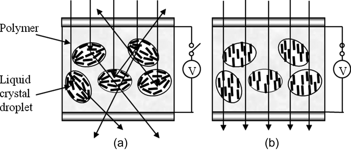
Liquid crystals (LCs) have been used to make switchable windows. The state-of-the-art technologies are polymer dispersed liquid crystals (PDLCs) and polymer stabilized cholesteric texture (PSCT) light shutters [1–4], which were developed at Kent State University. In PDLCs, liquid crystals exist in micron size droplets which are dispersed in an isotropic polymer. The concentration of the polymer is comparable to that of the liquid crystal. The polymer forms a continuous medium and the liquid crystal droplets are isolated from one another. The rod-like liquid crystal exhibits optical birefringence: ordinary refractive index no for light polarized perpendicular to the liquid crystal and extraordinary refractive index ne for light polarized parallel to the liquid crystal. The polymer is optically isotropic with the refractive index nP. The materials are chosen in such a way that nP = no < ne. In the absence of an electric field, either the droplet director orients randomly throughout the PDLCs or the liquid crystal director inside the droplet orients in all directions as shown in Figure 16.1a. When light propagates through a LC droplet, the encountered effective refractive index neff, which is between no and ne, is different from the refractive index nP of the polymer. Therefore light is scattered. When a sufficiently high electric field is applied across the PDLC film, the LC is aligned uniformly along the applied field (film normal direction) as shown in Figure 16.1b. For normal incident light, when it propagates through the LC droplet, the encountered effective refractive index is no which is matched to the refractive index nP of the polymer. Therefore light is transmitted.
Figure 16.1 Schematic diagram of the PDLC switchable window: (a) scattering state in the absence of electric field and (b) transparent state in the presence of electric field.
In a PSCT, the concentration of the cholesteric liquid crystal (ChLC) is usually much higher than that of the polymer. The liquid crystal forms a continuous medium while the polymer forms a network dispersed in the liquid crystal. Because of its helical structure, the ChLC exhibits three states: planar texture, focal conic texture, and homeotropic texture. The planar and homeotropic textures are uniform single domain structures and transmit light in broad wavelength regions. The focal conic texture is a poly-domain structure and scatters light. The dispersed polymer network stabilizes one or two of the three states in the absence of an electric field. An externally applied electric field can switch the PSCT between a scattering state and a transparent state.
There are many research papers, review papers, and books dedicated to PDLCs [5–9]. Since PSCTs have some superior optical properties, such as higher transmittance and larger viewing angle than the counterpart PDLC, this monograph will not discuss PDLCs further. Instead, it will concentrate on PSCT switchable windows.
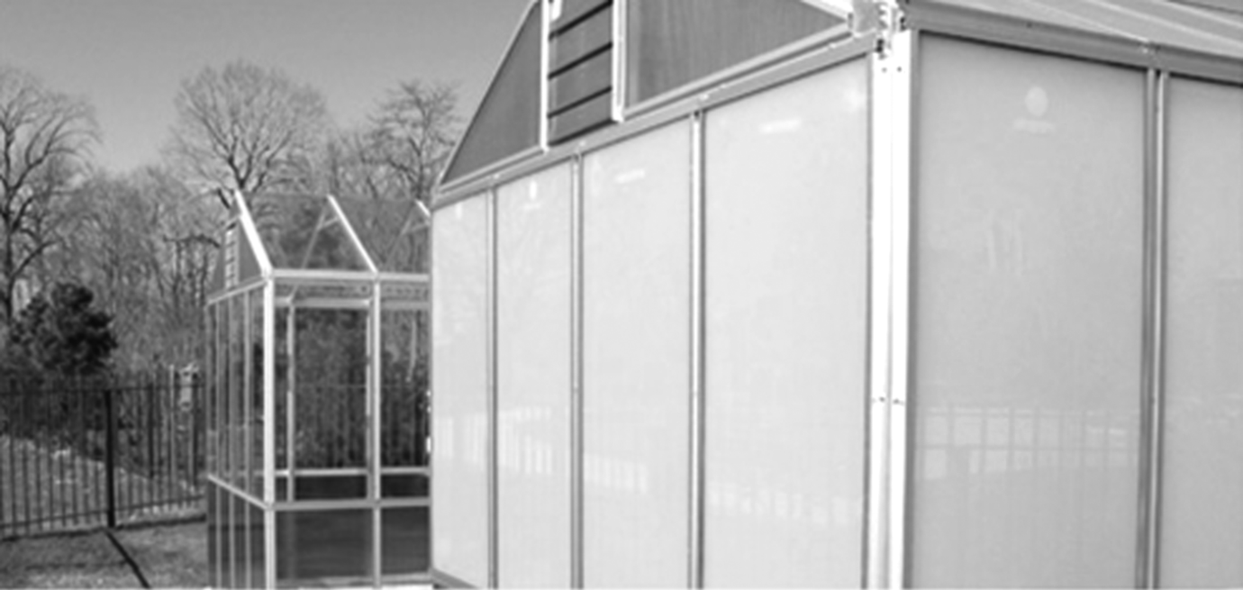
Scattering liquid crystal materials have been used for displays as well as for switchable windows because of the properties listed below. First, they do not use polarizers, and therefore they have high transmittance (~90%) and are compatible with flexible substrates with non-uniform birefringence. Second, they can be manufactured in large formats using a roll-to-roll process. Third, they have fascinating visual effects, no mechanically moving parts and instant switching. They can be used to make switchable windows to control not only privacy but also energy flow. In many situations privacy control is needed. Use in bathroom windows is such an example. The window usually should be transparent for open view and opaque occasionally for privacy. Figure 16.2 shows a liquid crystal switchable window manufactured by Polytronix Inc. Contemporary office buildings and residential houses have many windows. On bright sunny days, sunlight entering the buildings through windows attributes a lot to heating, which costs a significant amount of energy in air conditioning. Liquid crystal switchable windows can be used as architectural windows to control energy flow. When internal temperature is low (such as a cold winter day), the window is switched to the transparent state to allow sunlight to warm the building. In a hot summer day, the window is switched to the scattering state to stop sunlight entering the building, which reduces the heating effect. Also on a cold winter night, the window is switched to the scattering state to stop heat leakage by blackbody radiation out of the window. Figure 16.3 shows an experimental greenhouse with switchable liquid crystal window.
Figure 16.2 Photographs of liquid crystal switchable office window manufactured by Polytronix Inc. Photo courtesy of Polytronix Inc.
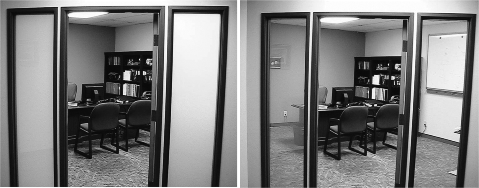
Figure 16.3 Photographs of green house with liquid crystal switchable window in Cleveland Botanic Garden. Photo courtesy of Cleveland Botanic Garden. (See the color version of this figure in Color Plates section.)
16.2 Cholesteric Liquid Crystal
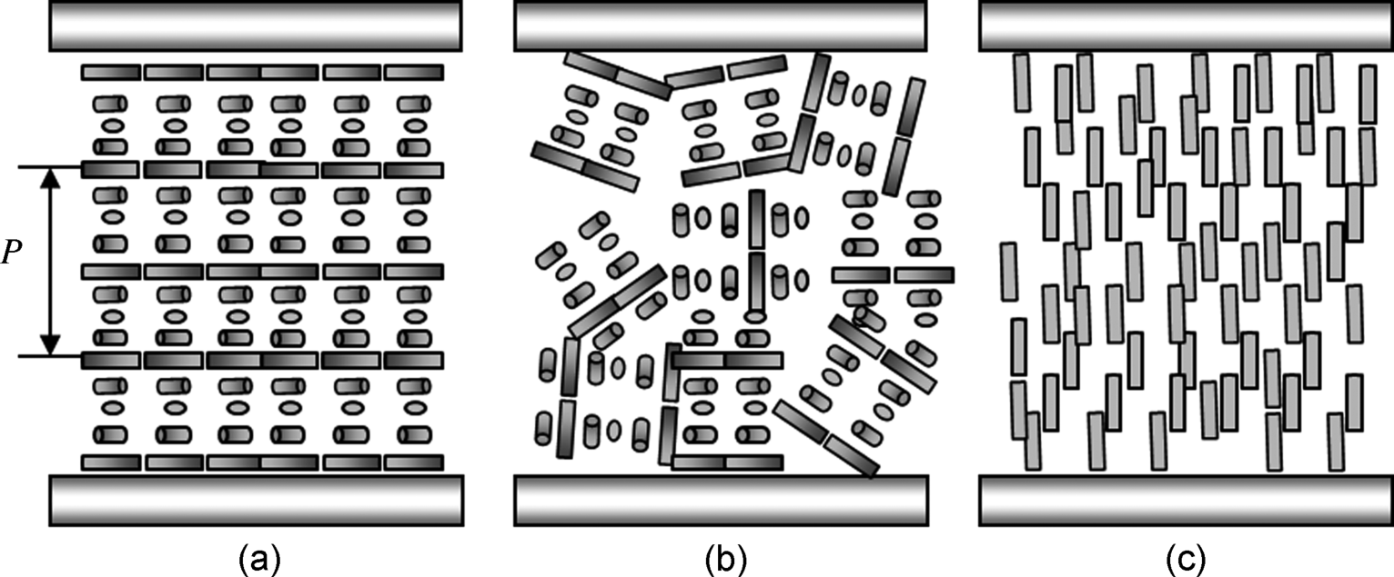
A ChLC possesses a helical structure where the liquid crystal twists around a helical axis as shown in Figure 16.4a [10–13]. The distance over which the liquid crystal rotates 360° is the pitch P. Depending on the orientations of the liquid crystal and the helical axis, the ChLC has three different states with different optical properties as shown in Fig. 16.4. In the planar texture, the LC possesses the helical structure with the helical axis parallel to the cell normal. In this state the liquid crystal exhibits a reflection band located at the wavelength λo = [(ne + no)/2]P with the bandwidth Δλ = (ne − no)P. Outside of the reflection band, the material is transparent. In the focal conic texture, the helical structure is preserved. The orientation of the helical axis, however, becomes random as shown in Figure 16.4b. The material has a poly-domain structure and scatters light, because the refractive index changes discontinuously from domain to domain. In the homeotropic texture, the helical structure is unwound by an external field, such as an electric field, and the liquid crystal is uniformly aligned as shown in Figure 16.4c. The liquid crystal is transparent.
Figure 16.4 Cholesteric textures: (a) planar texture, (b) focal conic texture, and (c) homeotropic texture.
16.3 Polymer Stabilization
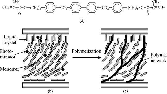
Polymer stabilized liquid crystals are composites of liquid crystal and polymer [14, 15]. They are constructed from a mixture of liquid crystal and monomers. The monomers usually have a rigid core and flexible tails like liquid crystal molecules as shown in Figure 16.5a. The concentration of the monomers is usually less than 10%. The monomers are directly dissolved in the liquid crystals as shown in Figure 16.5b. Although any type of polymerization method can be used, photo-initiated polymerization is fast and is usually used. The monomers are usually acrylate or methyl-acrylate because of their fast reaction rate. In order to form stable polymer networks, the (average) functionality of the monomers must be larger than 1. A small amount of photo-initiator, such as benzoin methyl ether, is added to the mixture. The concentration of the photo-initiator is typically 1–5% of the monomer. When irradiated under UV light, the photo-initiator produces free radicals which react with the double bonds of the monomer and initiate the chain reaction of polymerization. The UV intensity is usually a few mW/cm2 and the irradiation time is in the order of minutes.
Figure 16.5 Schematic diagram of polymer stabilized liquid crystal: (a) chemical structure of monomer 4,4′-bis-{4-[6-(acryloyloxy)-hexyloxy]benzoate}-1,1′-biphenylene, (b) before polymerization, and (c) after polymerization.
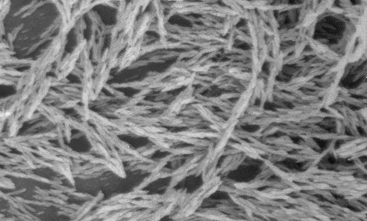
Before polymerization, the mixture of the monomer and the liquid crystal is in a liquid crystal phase. The polymerization environment is anisotropic due to the aligning effect of the liquid crystal on the monomer and the anisotropic diffusion of the monomer in the liquid crystal. Anisotropic fiber-like polymer networks, which mimic the structure of the liquid crystal during polymerization, are usually formed [14–17]. Figure 16.6 is an SEM (Scanning Electron Microscope) picture of a polymer network formed in the nematic phase. The lateral size of the polymer network is usually in the sub-micron region. Because the mixture of the liquid crystal and monomer is in a liquid crystal phase during polymerization, external fields and surface alignment techniques can be applied to create various polymer network structure, thereby achieving many fascinating structures.
Figure 16.6 SEM picture of the polymer network formed in homogenous aligned nematic phase. The picture was obtained by splitting the LC cell, immersing the cell in a solvent to remove the liquid crystal, evaporating the solvent and coating gold on the sample.
The morphology of the polymer network plays an important role in the performance of polymer stabilized cholesteric texture materials. In order to fabricate PSCTs with long-term stability, the monomers inside the network must be highly cross-linked and the lateral size of the network must be big enough [18]. The factors affecting the morphology are the structure of the monomer, UV intensity, photo-initiator type and concentration, and the temperature [16, 18]. Monomers with rigid core and two flexible tails usually form strong polymer networks which can withstand perturbation of external fields and temperature variations. Polymer networks formed by monomers without a rigid core usually reorient with liquid crystals when external electric fields are applied. The lateral size of polymer networks is determined by the polymerization rate, mobility, and concentration of monomers. Polymer networks with larger lateral sizes are obtained with lower polymerization rates which can be achieved with lower UV intensities or lower photo-initiator concentrations in photo-polymerization. Polymer network with larger lateral sizes are also obtained with high mobility of monomers, which can be achieved with higher polymerization temperature. When monomers are polymerized in the isotropic phase, the formed polymers have isotropic bead-like structures.
After polymerization, the anisotropic polymer networks formed affect the orientation of liquid crystals. They tend to keep the liquid crystal in the state (where the liquid crystal is parallel to the polymer network) during the polymerization [14, 15, 18–22]. The aligning effect of the polymer network on the liquid crystal can be considered as the anchoring imposed by the polymer network surface. The strength of the aligning effect depends on the structure of the monomer, the orientation order of the monomer in the polymer network, and the surface area of the polymer network. When the monomers in the polymer network are highly orientationally ordered, the aligning strength is strong; this can be achieved by polymerizing the monomers at a temperature much lower than the liquid crystal–isotropic transition temperature. The aligning strength is approximately linearly proportional to the polymer concentration. It is also linearly proportional to the surface area of the polymer network in per unit volume. Under a fixed polymer concentration, the surface area density is higher with smaller polymer network lateral size, and thus the aligning strength is stronger.
16.4 Polymer Stabilized Cholesteric Texture
PSCT materials can be operated in a variety of modes, depending on the curing condition, cholesteric pitch, polymer concentration, and dielectric anisotropy. The modes are normal mode, reverse mode, and bistable mode [23–25]. The normal mode PSCT material is scattering in the absence of voltage and becomes transparent when a voltage is applied across it. In contrast, the reverse mode PSCT material is transparent in the absence of voltage and becomes scattering when a voltage is applied cross it. The bistable PSCT material can be either scattering or transparent in the absence of voltage, depending on the history of voltage application. It can be switched between the scattering and transparent states by voltage pulses.
16.4.1 Normal Mode Polymer Stabilized Cholesteric Texture
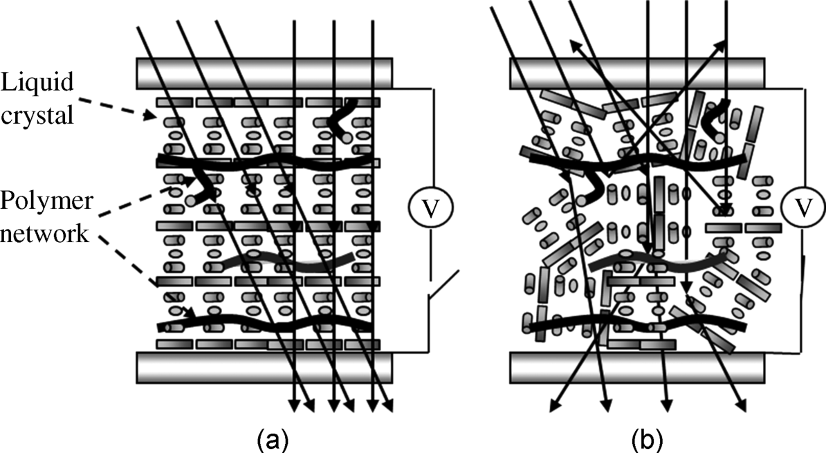
The normal mode polymer stabilized cholesteric texture material is made from a mixture of a ChLC with a positive dielectric anisotropy (Δε > 0) and a small amount of monomers [22, 23, 26–28]. The pitch of the ChLC is a few microns (~0.5–5 μm). No special cell surface treatment is needed. The substrates have a transparent ITO (Indium Tin Oxide) electrode. When the monomers are polymerized, the mixture is in the homeotropic texture in the presence of an external field in the cell normal direction. The polymer network formed is perpendicular to the cell surface as shown in Figure 16.7.
Figure 16.7 Schematic diagram showing how the normal mode polymer stabilized cholesteric texture switchable window works.
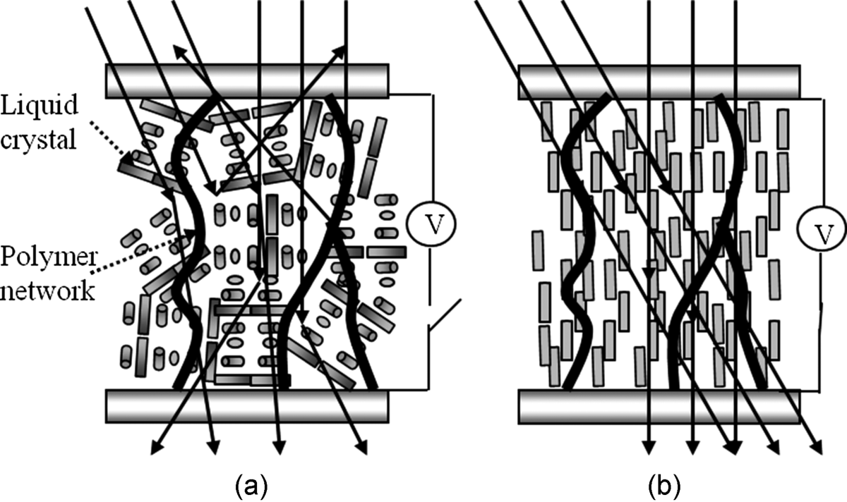
After the polymerization, the inter-molecular interaction between liquid crystal molecules tends to form the helical structure while the interaction between the liquid crystal and the polymer network tends to keep the liquid crystal in the unwound homeotropic texture. The competition between these two interactions results in the focal conic texture as shown in Figure 16.7a. In this texture, the ChLC forms many micron-size domains. In each domain, the LC is in the twisted Ch structure along a helical axis. The orientation of the helical axis, however, changes from domain to domain. The refractive index changes abruptly from domain to domain. When a light (incident normally or obliquely) propagates through the PSCT material, it is scattered away from the original incident direction and the material is opaque. Without the polymer network, the ChLC may relax to the planar texture or the focal conic domain size may change gradually, and become less scattering. The polymer network stabilizes the focal conic texture at zero voltage and maximizes the scattering. When a sufficiently high voltage is applied across the cell, the liquid crystal (Δε > 0) is switched to the homeotropic texture as shown in Figure 16.7b, because the liquid crystal tends to orient parallel to the applied electric field direction. The PSCT material is in the uniform aligned state and therefore it becomes transparent. Because the concentration of the polymer is low and both the liquid crystal and the polymer are aligned in the cell normal direction, the normal mode PSCT material is transparent at any viewing angle. The photograph of a normal mode PSCT switchable window is shown in Figure 16.8.
Figure 16.8 Photographs of normal mode polymer stabilized cholesteric texture switchable window: (a) scattering focal conic texture in the absence of voltage and (b) transparent homeotropic texture in the presence of voltage. Photo courtesy of Kent Optronics Inc.
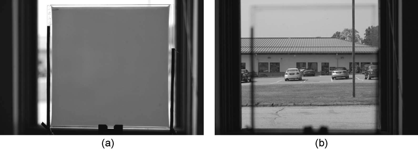
Figure 16.9 shows the transmittance of a normal mode PSCT switchable window [29]. The cell thickness is 15 μm. The helical pitch is about 0.8 μm. The monomer is RM257 (from Merck) which is bifunctional. The concentration of the monomer is 2.0 wt%. The light source for the measurement is a He–Ne green laser at wavelength of 543.5 nm. The full linear collection angle of a circular photo detector for measurement is 9.5°. At 0 V, the PSCT material is in the focal conic texture and the transmittance of the PSCT material is less than 2%. As the applied voltage is gradually increased, the liquid crystal is tilted toward the cell normal direction. The domain size increases and the effective birefringence decreases. Therefore the transmittance increases. When the voltage is increased above 40 V (the driving voltage), the helical structure is unwound and the liquid crystal is uniformly aligned in the cell normal direction (so is the polymer network). The maximum transmittance of 87% is reached. The transmittance is normalized to the incident light. The light loss is due to the reflections from the two air–glass interfaces and ITO–glass interfaces. The PSCT material is very transparent. When the voltage is gradually decreased, the PSCT material relaxes back to the focal conic texture and its transmittance decreases. It is worth noting that the transmittance at 0 V is about 5%, different from the initial transmittance at 0 V. This difference is caused by the fact that the focal conic domain size depends on how the applied voltage is removed. The scattering of the PSCT material depends on how close the domain size is to the wavelength of light. If the applied high voltage is removed suddenly, smaller domains form and the transmittance of 2% is obtained. If the applied high voltage is removed gradually, larger domains form and the transmittance of 5% is obtained.
Figure 16.9 Transmittance as a function of applied voltage of the normal mode PSCT switchable window.
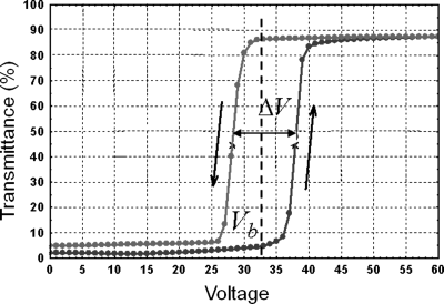
Also note in Figure 16.9 that there is a hysteresis in the transition between the focal conic state and the homeotropic state. With increasing voltage, the transmittance of {[(87% + 2%)/2] = 44.5%} is obtained at 38 V while with decreasing voltage, the same transmittance is obtained at 28 V. The hysteresis is ΔV = 38 V − 28 V = 10 V. On one hand, the normal mode PSCT is not suitable for gray scale operation because of the hysteresis. On the other hand, the hysteresis can be used to make multiplexed switchable window on a passive matrix [25, 30]. The PSCT material is bistable at the bias voltage Vb = (38 V + 28 V)/2 = 33 V. When the applied voltage is increased from 0 V to 33 V, the PSCT material is scattering. When the applied voltage is decreased from 50 V to 33 V, the PSCT material is transparent. The hysteresis can be enhanced by the polymer network. Figure 16.10 shows the transmittance–voltage curves of normal mode PSCT windows made with a variety of polymer concentrations. When the polymer concentration is increased from 2.5% to 4.5%, the hysteresis ΔV increases from 8 V to 16 V. When the polymer concentration is increased, the voltage to switch the PSCT material to the transparent homeotropic state decreases slightly, while the voltage at which the material relaxes to the scattering focal conic state decreases greatly. When the polymer concentration is sufficiently high, the PSCT material will remain in the homeotropic texture even when the applied voltage is completely removed. We will discuss this phenomenon in more detail in the bistable mode PSCT window. Figure 16.11 shows photos of normal mode PSCT multiplexed display on a passive matrix made by Kent Optronics Inc.
Figure 16.10 Transmittance as a function of applied voltage of the normal mode PSCT window with different polymer concentrations.
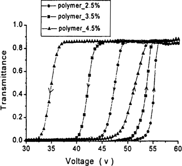
Figure 16.11 Photographs of PSCT multiplexed display on a passive matrix developed by Kent Optronics Inc. (KOI): (a) scattering state at zero voltage, (b) transparent state at high voltage, and (c) bistable states at bias voltage. Photo courtesy of KOI.

In order to scatter visible light strongly, the focal conic domain size of the PSCT material in the scattering state has to be around the wavelength of the light. The main factors affecting the domain size are helical pitch, polymer concentration, and curing UV intensity. The trend is that smaller domains are obtained with shorter helical pitch, higher polymer concentrations, higher photo-initiator concentrations, and higher curing UV intensities. The scattering of the focal conic texture also is stronger with larger birefringence and thicker cell thickness.
The driving voltage of a normal mode PSCT window is the voltage needed to obtain 90% of the maximum transmittance, determined by helical pitch, dielectric anisotropy of the liquid crystal, twist elastic constant, and polymer concentration. Without the polymer network, the driving voltage is governed by the equation (in SI unit) ![]() , where h is the PSCT cell thickness, P is the helical pitch, K22 is the twist elastic constant, and Δε is the dielectric anisotropy [10]. The polymer network tends to align the LC in the cell normal direction, the same as the applied electric field. Therefore the driving voltage decreases with increasing polymer concentration as shown in Figure 16.10.
, where h is the PSCT cell thickness, P is the helical pitch, K22 is the twist elastic constant, and Δε is the dielectric anisotropy [10]. The polymer network tends to align the LC in the cell normal direction, the same as the applied electric field. Therefore the driving voltage decreases with increasing polymer concentration as shown in Figure 16.10.
The normal mode PSCT switchable window has quite different rising and falling times. The rising time τr (from the scattering focal conic texture to the transparent homeotropic texture) is in the order of 10 ms when the applied voltage is 1.5 times higher than the driving voltage. The rising time can be dramatically reduced by applying higher voltage. It has a small dependence of the helical pitch and is independent of the polymer concentration. The falling time τf (from the transparent state to the scattering state) is in the order of ms. It can be dramatically reduced by using ChLC with shorter pitches, because the energy difference between the unwound state (homeotropic texture) and the twisted state (focal conic texture) is bigger for ChLCs with shorter pitches. The relation between them can be approximately described by ![]() , where γ is the rotational viscosity coefficient. In contrary, the falling time increases with increasing polymer concentration, because the polymer network tends to keep the PSCT material in the homeotropic texture.
, where γ is the rotational viscosity coefficient. In contrary, the falling time increases with increasing polymer concentration, because the polymer network tends to keep the PSCT material in the homeotropic texture.
16.4.2 Reverse Mode Polymer Stabilized Cholesteric Texture
The reverse mode PSCT switchable window is also made from a mixture of cholesteric liquid crystal (Δε > 0) and a small amount of monomers [22, 23, 31]. The pitch of the liquid crystal is a few microns (~3–15 μm). The mixture is filled into a cell with homogeneous alignment layers. The mixture is in the planar texture in the absence of voltage because of the alignment layers. The monomers are polymerized in the planar texture. The polymer network formed is parallel to the cell surface, as shown in Figure 16.12.
Figure 16.12 Schematic diagram showing how the reverse mode polymer stabilized cholesteric texture switchable window works.
After polymerization, the PSCT material is stabilized in the planar texture in the absence of voltage, as shown in Figure 16.12a. Because the pitch is in the infrared region, the material is transparent for visible light incident in all directions. When a sufficiently high voltage is applied across the cell, the field tends to align the liquid crystal in the cell normal direction while the polymer network tends to keep the liquid crystal in the planar texture. As a result of the competition between these two forces, the liquid crystal is switched to the poly-domain focal conic texture as shown in Figure 16.12b, and the material becomes scattering. When the applied voltage is removed, the PSCT material returns to the planar texture. A photograph of reverse mode PSCT switchable window is shown in Figure 16.13.
Figure 16.13 Photographs of normal mode polymer stabilized cholesteric texture switchable window: (a) transparent planar texture in the absence of voltage and (b) scattering focal conic texture in the presence of voltage.
The transmittance–voltage curves of two reverse mode PSCT switchable window are shown in Figure 16.14 [29]. The cell thickness is 10 μm and the pitch length is about 4 μm. The light source is a He–Ne green laser and the light is incident normally on the PSCT cells. The full linear collection angle of a circular photo detector for measurement is 9.5°. The concentration of the bifunctional monomer is about 5%. The transmittance is normalized to the incident light. At 0 V, the PSCT material is in the transparent planar texture with the transmittance about 85%. The main light loss is due to the reflection from the air–glass interfaces and ITO–glass interfaces. A small amount of the lost light is due to the residual scattering caused by the refractive index mismatch between the liquid crystal and the polymer network. When a voltage about a threshold value Vt is applied, the liquid crystal begins to tilt away from the cell plane. The material is gradually switched to the scattering focal conic texture and the transmittance decreases. The transmittance becomes a minimum when an appropriate voltage Vm is applied. When the applied voltage is increased further, the transmittance increases slightly, because the liquid crystal tilts too much to the cell normal direction and the effective birefringence start to decreases. When the applied voltage is decreased from Vm, the material relaxes back to the planar texture and the transmittance increases. It is worth to point out that in reverse mode PSCT, the polymer network must be strong. When the liquid crystal reorients under the influence of the applied electric field, it exerts a force on the polymer network. If the polymer network is not strong, it will reorient with the liquid crystal. When the applied electric field is removed, the polymer network may not be able to relax to the direction parallel to the cell surface, which will result in a residual scattering.
Figure 16.14 Transmittance as a function of applied voltage of the reverse mode PSCT switchable window.
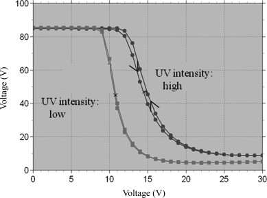
In order to scatter visible light, the focal conic domain size should be close to the wavelength of the light. The domain size is determined by the polymer concentration, morphology, and helical pitch. The trend is that the domain size becomes smaller with higher polymer concentration, higher curing UV intensity, and shorter pitch. As shown in Figure 16.14, the PSCT material cured under the high UV intensity has a lower scattering efficiency, because the domain size is too small. Higher scattering efficiency can be achieved with larger birefringence and thicker cell.
Reverse mode PSCT materials have fast response time. When the applied voltage is 1.5 times higher than the minimum transmittance voltage Vm, the falling time τr (from the planar texture to the focal conic texture) is about a few ms. The rising time τr (from the focal conic texture to the planar texture) is also about a few ms. The rising time can be reduced by increasing the polymer concentration, decreasing the helical pitch, and using low curing UV intensity.
In some applications, such as bathroom window, the window needs to be transparent most of the time, and opaque (scattering) occasionally. The reverse mode PSCT material is more suitable for this type of application. It is also more desirable for safety reason. For example, it can be used for automobile windows which will be transparent when electric power is lost.
16.4.3 Bistable Mode Polymer Stabilized Cholesteric Texture
The liquid crystal switchable windows (PDLC, normal, and reverse mode PSCT) discussed so far are mono-stable. They are opaque (optical scattering) at one voltage condition and transparent at another voltage condition. A voltage must be applied to sustain one of the optical states. Although liquid crystals are dielectric media, in reality their conductivities are not zero because of impurities. Therefore the switchable windows consume some energy when a voltage must be applied in prolonged periods. A bistable window is highly desirable, in which both the opaque and transparent states are stable in the absence of voltage; and window can be switched between the two states by a voltage pulse.
The bistable mode PSCT switchable window is based on the normal mode PSCT material [25]. As shown in Section 4.1, for the PSCT material with sufficiently high polymer concentration, it is switched from the scattering focal conic texture to the transparent homeotropic texture when a sufficiently high voltage is applied; it remains in the homeotropic texture when the applied voltage is removed. Therefore the PSCT material has two stable states in the absence of voltage: the scattering focal conic texture and the transparent homeotropic texture. What is needed now is a means to switch the material between the two states. Dual frequency liquid crystal can be used to accomplish this task. Under a low frequency electric field, it has a positive dielectric anisotropy and tends to align parallel to the electric field while under a high frequency electric field, it has a negative dielectric anisotropy and tends to align perpendicular to the electric field. When a dual frequency LC is used in the bistable mode PSCT, a low frequency voltage switches the material from the focal conic texture to the homeotropic texture and a high frequency voltage switch the material from the homeotropic texture to the focal conic texture.
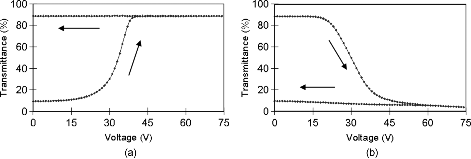
Figure 16.15 shows the response of the bistable mode PSCT window to applied voltages [28]. The dielectric anisotropy of the material is about +2.2 at 100 Hz and −2.0 at 20 kHz. The pitch of the material is about 1.6 μm. The concentration of a bi-functional acrylate monomer is 8.0%. The cell thickness is 10 μm. The switchable window is prepared in the same way as the normal mode PSCT window. The formed polymer network is perpendicular to the cell surface and tends to align the material in the homeotropic texture. In the electro-optical measurement, a white light from an arc lamp was used. The collection angle of the detection was 4.7°. Figure 16.15a shows the response of the bistable mode material to the applied voltage with a frequency of 100 Hz. It is initially in the focal conic texture with a low transmittance less than 10%. When the voltage is increased, the material is switched to the homeotropic texture with a high transmittance about 87%. When the voltage is removed, it remains in the homeotropic texture with the high transmittance. In the homeotropic texture, the liquid crystal molecules are parallel to the polymer network and the strong aligning force of the polymer prevents the liquid crystal from reorienting away from the polymer network direction when the applied voltage is removed. Figure 16.15b shows the response of the bistable mode PSCT window to the applied voltage with a frequency of 20 kHz. The material is initially in the homeotropic texture with the high transmittance. When the voltage is increased, it is switched to the focal conic texture with the low transmittance. When the voltage is removed, the material remains in the focal conic texture and the transmittance remains low. In the focal conic texture, the orientation of the liquid crystal molecules with respect to the polymer network is more or less random and the aligning force of the polymer network cannot unwind the helical structure. It is worth to point out that the concentration of the polymer must be properly chosen. If the polymer concentration is too low, its aligning effect will be weak and cannot hold the PSCT material in the homeotropic texture when the low frequency voltage is removed. If the polymer concentration is too high, its aligning effect will be strong and will pull the PSCT material from the focal conic texture to the homeotropic texture when the high frequency voltage is removed.
Figure 16.15 Response of the bistable mode PSCT switchable window to applied voltages with different frequencies: (a) 100 Hz and (b) 20 kHz.
In the absence of voltage, the bistable mode PSCT switchable window can be either in the focal conic texture with low transmittance or the homeotropic texture with high transmittance. Voltage pulses with different frequencies can be used to switch it back and forth. Figure 16.16a shows the response of the PSCT material initially in the homeotropic texture to a 500 ms wide high frequency voltage pulse [25]. The amplitude of the pulse is 50 V and the frequency is 20 kHz. Before the pulse the material is in the homeotropic texture with high transmittance. When the high frequency voltage pulse is applied, the material is switched to the focal conic texture and the transmittance decreases. After the pulse, the material remains in the focal conic texture except for a small reorientation of the LC as indicated by the slight increase of the transmittance. Figure 16.16b shows the response of the PSCT material initially in the focal conic texture to a 500 ms wide low frequency voltage pulse. The amplitude of the pulse is 50 V and the frequency is 100 Hz. Before the pulse, the material is in the focal conic texture with low transmittance. When the low frequency voltage pulse is applied, the material is switched to homeotropic texture and the transmittance increases. After the pulse, the material remains in the homeotropic texture with high transmittance. If the voltage pulse is short, it will not be able to switch the PSCT material into the maximum or minimum transmittance states. Gray scale is possible by varying the pulse width because of the multi-domain structure of the PSCT cell.
Figure 16.16 Response of the bistable mode PSCT switchable window to voltage pulses with different frequencies: (a) 20 kHz and (b) 100 Hz.
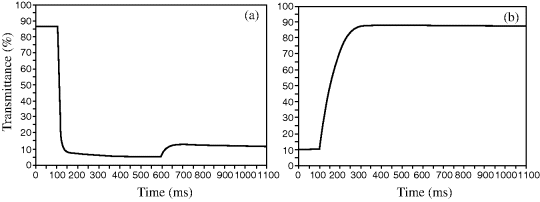
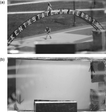
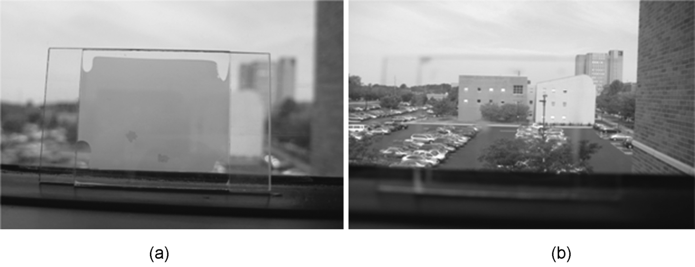
Figure 16.17a shows a photograph of the bistable mode PSCT switchable window in the absence of voltage after being switched to the focal conic texture by the high frequency voltage pulse [25]. The light shutter is scattering and blocks the scene behind. Figure 16.17b shows a photograph of the PSCT window in the absence of voltage after being switched to the homeotropic texture by the low frequency voltage pulse. The window is transparent and the scene behind is visible.
Figure 16.17 Photographs of the bistable mode PSCT switchable window in the absence of voltage: (a) opaque state and (b) transparent state.
The PSCT windows are used for privacy control. They can be used to control energy flow through architectural windows. Contemporary office buildings and resident houses have many windows. In a hot summer day, sunlight entering the buildings through windows heats the building and air conditioning the buildings costs a great amount of energy. It is desirable to have smart windows that can automatically block sunlight when the temperature inside the building increases to a preset value. It is indeed possible to develop this type of smart window, which is switched to the transparent homeotropic texture by applied voltage and is switched to the scattering focal conic texture by ambient temperature.
The smart window is also based on the normal mode PSCT material and prepared in the same way as the normal mode window [24]. The cholesteric liquid crystal has a positive dielectric anisotropy and the helical pitch about 1 μm. The cholesteric to isotropic transition temperature is about 50°C. The used monomer is bifunctional and its concentration is 5%. In the electro-optical measurement, a white light from an arc lamp is used. The collection angle of the detection was 4.7°. The voltage applied to the cells is AC voltage with the frequency of 1 kHz. The formed polymer network is perpendicular to the cell substrates and tends to align the LC into the homeotropic texture. Both the focal conic and homeotropic textures are stable in the absence of voltage.
Figure 16.18a shows the response of the smart PSCT material to applied voltage. Initially, it is in the scattering focal conic texture with a low transmittance of 2%. When the applied voltage is increased, it is gradually switched to the homeotropic texture with a high transmittance of 87%. When the voltage is removed, it remains in the homeotropic texture with the high transmittance, due to the strong aligning effect of the polymer network.
Figure 16.18 Response of the smart bistable mode PSCT switchable window to applied voltage and temperature: (a) 1 kHz voltage and (b) temperature.
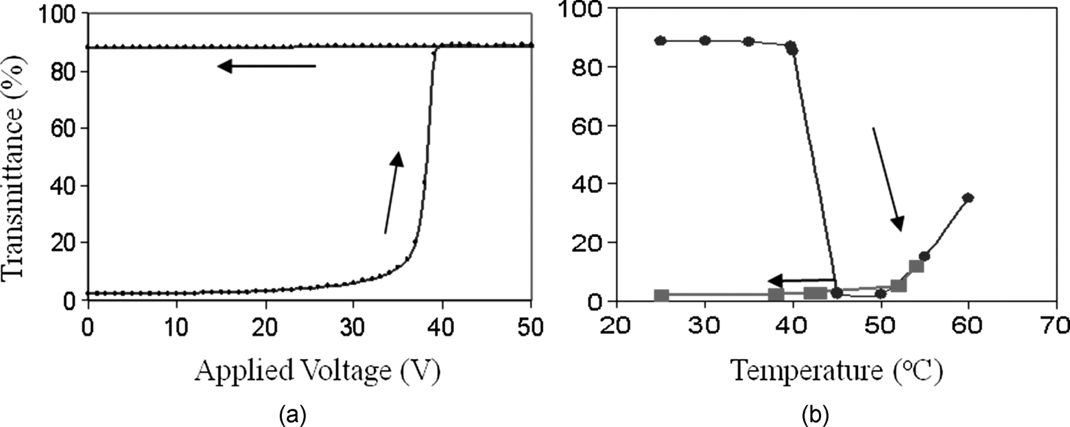
Figure 16.18b shows the transmittance of the smart PSCT material as a function of temperature. It is initially in the transparent homeotropic texture. It remains in the transparent state at temperature below 40°C. When the temperature is increased above that, the PSCT material transforms into the scattering focal conic texture and its transmittance decreases. The physics behind the transition is the decrease of the aligning force of the polymer network with increasing temperature. When the temperature is sufficiently high, the polymer network is no longer able to hold the liquid crystal in the homeotropic texture. The transmittance remains low until the cholesteric–isotropic transition. When the liquid crystal starts to transform into the isotropic state, transmittance of the PSCT material increases. Once the PSCT material is in the focal conic texture or isotropic state, it will remain in the focal conic texture with the low transmittance when the ambient temperature is decreased.
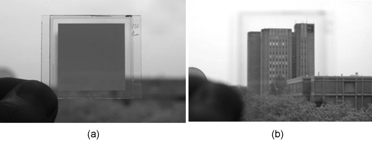
Figure 16.19 shows photographs of the smart PSCT window in the absence of voltage and at 25°C [24]. The PSCT window is bistable. Figure 16.19a show the photograph of the PSCT window in the scattering focal conic texture. It blocks the scene behind. Figure 16.19b shows the photograph of the window in the homeotropic texture. It is transparent and the scene behind is visible.
Figure 16.19 Photographs of the smart bistable mode PSCT switchable window in the absence of voltage: (a) opaque state and (b) transparent state.
16.5 Conclusion
Polymer stabilized cholesteric texture materials are used to make switchable windows for privacy control. They can be operated in normal mode, reverse mode, and bistable mode, depending on the polymer concentration, helical pitch, and curing condition. Polymer stabilized cholesteric texture switchable windows have the advantages of high transmittance transparent state, large viewing angle, and instant switching (in a few ms). They are good candidates for switchable architectural and greenhouse windows to control light energy flow. Research is underway to maximize the backward scattering in the scattering state.
1. J. W. Doane, N. A. Vaz, B.-G. Wu, and S. Zumer. Field controlled light scattering from nematic microdroplets. Appl. Phys. Lett. 1996, 48, 269.
2. P. S. Drzaic. Polymer dispersed nematic liquid crystal for large area displays and light valves, J. Appl. Phys. 1986, 60, 2142.
3. J. L. Fergason. Polymer encapsulated nematic liquid crystals for scattering and light control applications. SID Int. Symp. Digest Tech. Papers 1985, 16, 68.
4. D.-K. Yang, L. C. Chien, and J. W. Doane. Cholesteric liquid crystal/polymer gel dispersion for haze-free light shutter. Appl. Phys. Lett. 1992, 60, 3102.
5. P. S. Drzaic. Liquid Crystal Dispersions, World Scientific, NJ, 1995.
6. G. P. Crawford and S. Zumer. Liquid Crystals in Complex Geometries, Taylor & Francis, London, 1996.
7. J. W. Doane. Polymer dispersed liquid crystal displays. In: B. Bahadur, Ed., Liquid Crystals, Applications and Uses, vol. 1, World Scientific, Singapore, 1990, Chapter 14.
8. H.-S. Kitzerow. Polymer-dispersed liquid crystals, from the nematic curvilinear aligned phase to ferroelectric films. Liq. Cryst. 1994, 16, 1.
9. G. P. Crawford, J. W. Doane, and S. Zumer. Polymer dispersed liquid crystals: nematic droplets and related systems. In: P. J. Collings and J. S. Patel, Eds., Handbook of Liquid Crystal Research, Oxford University Press, New York, 1997, Chapter 9.
10. P. G. de Gennes and J. Prost. The Physics of Liquid Crystals, Oxford University Press, New York, 1993.
11. S. Chandrasekhar. Liquid Crystals, 2nd Edition, Cambridge University Press, New York, 1997.
12. D.-K. Yang and S.-T. Wu. Fundamentals of Liquid Crystal Devices, John Wiley & Sons, 2006.
13. S.-T. Wu and D.-K. Yang. Reflective Liquid Crystal Displays, John Wiley & Sons, Ltd., 2001.
14. D. J. Broer. Liquid crystalline networks formed by photoinitiated chain cross-linking. In: G. P. Crawford and S. Zumer, Eds., Liquid Crystals in Complex Geometries, Taylor & Francis, London, 1996.
15. R. A. M. Hikmet. Anisotropic gels obtained by photopolymerization in the liquid crystal state. In: G. P. Crawford and S. Zumer, Eds., Liquid Crystals in Complex Geometries, Taylor & Francis, London, 1996.
16. Y. K. Fung, D.-K. Yang, Y. Sun, L. C. Chien, S. Zumer, and J. W. Doane. Polymer networks formed in liquid crystals. Liq. Cryst. 1995, 19, 797.
17. G. A. Held, L. L. Kosbar, I. Dierking, A. C. Lowe, G. Grinstein, V. Lee, and R. D. Miller. Confocal microscopy study of texture transitions in a polymer stabilized cholesteric liquid crystal. Phys. Rev. Lett. 1997, 79, 3443.
18. R. Q. Ma and D.-K. Yang. Freedericksz transition in polymer stabilized nematic liquid crystals. Phys. Rev. E 2000, 61, 1576.
19. Y. K. Fung, A. Borstnik, S. Zumer, D.-K. Yang, and J. W. Doane. Pretransitional nematic ordering in liquid crystals with dispersed polymer networks. Phys. Rev. E 1997, 55, 1637.
20. P. Bos, J. Rahman, and J. Doane. SID Digest Tech. Pap. 1993, XXIV, 887.
21. H. Kikuchi, M. Yokota, Y. Hisakado, H. Yang, and T. Kajiyama. Polymer-stabilized liquid crystal blue phases. Nat. Mater. 2002, 1, 111.
22. R. E. Kraig, P. L. Taylor, R. Q. Ma, and D.-K. Yang. Nematic order in polymer stabilized liquid crystal. Phys. Rev. E 1998, 58, 4594.
23. D.-K. Yang, L.-C. Chien, and Y. K. Fung. Polymer stabilized cholesteric textures: materials and applications. In: G. P. Crawford and S. Zumer, Eds., Liquid Crystals in Complex Geometries, Taylor & Francis, London, 1996.
24. R. Bao, C.-M. Liu, and D.-K. Yang. Smart bistable polymer stabilized cholesteric texture light shutter. Appl. Phys. Express 2009, 2, 112401.
25. J. Ma, L. Shi, and D.-K. Yang. Bistable polymer stabilized cholesteric texture light shutter. Appl. Phys. Express 2010, 3, 021702.
26. R. Sun, W. Jang, and D.-K. Yang. Optimization of polymer stabilized cholesteric texture materials for high-brightness projection displays. SID Int. Symp. Digest Tech. Papers 1999, XXX, 652.
27. S. Hurley, J. Ma, and D.-K. Yang. A flexible display using dye-doped PSCT. SID Int. Symp. Digest Tech. Papers 2009, XXXX, 1520.
28. J. Ma, S. Hicks, S. Hurley, and D.-K. Yang. Effect of pressure on polymer stabilized cholesteric. SID Int. Symp. Digest Tech. Papers 2009, XXXX, 1532.
29. S. Hurley.Liquid crystal displays for pixelated glare shielding eyewear, Dissertation, Kent State University Publication, 2010.
30. F. Zhang and D.-K. Yang. Polymer stabilized cholesteric dichroic dye displays. SID Int. Symp. Digest Tech. Papers 2002, XXXIII, 469.
31. R. Q. Ma and D.-K. Yang. Polymer stabilized cholesteric texture reverse-mode light shutter: cell design. J. SID 1998, 6, 125.
