ATM—ASYNCHRONOUS TRANSFER MODE
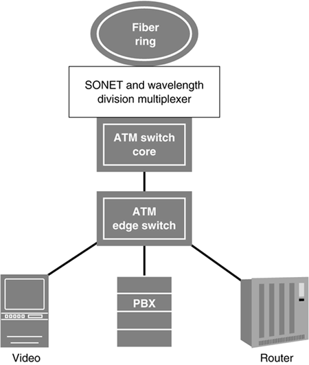
ATM, or asynchronous transfer mode, is a high-speed (up to 30 Gigabits) switching service capable of carrying voice, data, video and multimedia images. ATM is used primarily in Frame Relay networks and in newer carrier networks. The key advantage of ATM is that it enables providers and end users to carry multiple types of traffic without building separate networks for voice, video and data. Currently, many carriers have separate networks for voice, Frame Relay and Internet traffic. They merge the traffic in the core over SONET and dense wavelength division multiplexing (DWDM). (See Figure 6.12.) It was thought that IP routers in converged networks would replace ATM. However, because of ATM's superior quality of service capabilities, this has not happened.
Figure 6.12. ATM for many types of service.
While not widely used by retail customers, large enterprises deploy ATM as a way to send large files such as video between sites. For example, the entertainment industry uses it to ship film clips to other locations for editing. Gigabit Ethernet, where it's available, is a lower cost option than ATM for end users who need to send large files between sites.
The distinguishing point about asynchronous transfer mode (ATM) is that it can prioritize traffic. It assigns qualities of service (QoS) to different types of traffic. ATM carries parallel streams of traffic at different levels of service quality over the same circuit.
Asynchronous transfer mode (ATM) is used by:
Long distance providers
Bell telephone companies' data networks
competitive local exchange carriers
DSLAM connections to ISPs
Cable TV networks
Frame Relay networks
Fortune 500 companies
ATM's speed is due to three characteristics:
The cells are fixed in size.
The cells are switched in hardware in a connection-oriented manner.
Switching is performed asynchronously.
Fixed-Sized Cells—Less Processing
Asynchronous transfer mode (ATM) packages data into discrete groups called cells. This is analogous to putting the same number of letters into each envelope. Handling fixed-sized cells requires less processing than switching with variable-sized packets. The ATM switch does not have to look for bits telling it when the cell is over. Each cell is 53 bytes long. The switch knows when the cell ends.
Five of the 53 bytes contain header information. This includes bits that identify the type of information contained in the cell (e.g., voice, data or video) so that the cell can be prioritized. Voice and video need constant bit-rate transmission so that there is no interruption in the voice or picture. LAN data typically uses variable bit-rate service. Other header information is used for routing, putting the cells in the correct sequence and error checking. The remaining 48 bytes are the “payload”—user data such as voice, video or sales proposals.
Switching in Hardware—Less Address Lookup
A significant reason why ATM is fast is that the cells are switched in the hardware. This means that an ATM switch does not have to look up each cell's address in software. Rather, an ATM switch sets up a route through the network when it sees the first cell of a transmission. It puts this information into its hardware and sends each cell with the same header routing information down the virtual path previously established. For example, all cells with XXX in the header use route 234. Using the same path for each cell makes ATM a connection-oriented service.
Asynchronous Switching—Improving Network Utilization
With asynchronous switching, every bit of the network capacity is available for every cell. This is different than synchronous multiplexing technologies such as T-1 and T-3. With T-3 multiplexing, every one of the 672 input transmissions is assigned a time slot. For example, terminal A may be assigned time slot 1 and terminal B assigned time slot 2. If terminal A has nothing to send, the time slot is sent through the network empty. ATM has no synchronous requirements. It statistically multiplexes cells onto the network path based on quality of service information in the header. For example, voice and video need better service, fewer delays and higher aggregate speeds than e-mail messages. With ATM, this is accomplished without wasting network capacity. Every cell is used.
Bursting—Selling More Than the Total Capacity
Because not every device connected to a public network sends data all of the time, Frame Relay and DSL carriers that use ATM have the capability to sell aggregate capacity that is higher than the total available capacity. This is called the capability to oversubscribe. For example, Frame Relay customers may order ports at 64 Kbps. However, they can “burst” to higher speeds, for example, 512 Kbps. Their data is sent in pauses between other customers' data. The same thing happens with digital subscriber line access multiplexers (DSLAMs). DSLAMs that use ATM connections to send DSL data to Internet service providers have a top speed that is lower than the sum of the DSL modems connected to them. (See Figure 6.7 earlier in this chapter.)
Scalability—The Ability to Use ATM for High- and Low-Speed Applications and IP Traffic
ATM can carry traffic of various speeds. It accepts streams from different inputs (e.g., central office switches and routers) and sends them across paths, or virtual circuits established by the ATM switch. This is scalability. ATM can be scaled from low-speed (56 kilobit) to high-speeds used for video and multimedia applications. ATM is installed mainly in carrier networks. Many new carriers have built networks capable of transmitting traffic from many sources including ISP Internet traffic, CLEC voice traffic and Gigabit Ethernet traffic. Some ATM switches also carry IP traffic. Some of them have the capability to read IP routing information in packets. The switch puts IP packets into cells and reassembles the cells back into packets at the end of the transmission. This is referred to as mapping IP onto ATM.
ATM—Edge and Core Devices
Frame Relay carrier networks use ATM switches extensively for switching multiple customers' traffic at gigabit speeds over their core or backbone facilities. Frame Relay vendors use Frame Relay devices to connect directly to their customers at the edge of the network. The edge of the network is the point where traffic enters and leaves the network. The edge of the network where traffic exits the network is known as the egress point. Most carriers now deploy multiplatform switches with both Frame Relay and ATM ports. The switch converts the frames to cells and transports them through the network.
Some carriers are conducting trials of the use of ATM switches as a replacement for tandem central offices. Tandem central offices switch traffic between central offices and do not have connections directly to end users. The use of ATM would increase the speed of circuits between tandem offices, which now use T-3 service. The ATM switches would be able to carry data as well as voice in the backbone of metropolitan area networks.
Elements of an ATM Network
The ITU has defined the elements of an ATM network. The elements are:
User Network Interface
Quality of service
Connections between customer locations
These elements are important because they create a common way to prioritize traffic, send traffic between sites and create connections to ATM networks.
Communicating Between ATM and Frame Relay Services—Frame Relay ATM Interworking
Frame Relay networks use ATM to transmit customer data. This requires Frame Relay to ATM Interworking where frames are converted to ATM cells as they enter the network. The ATM cells are converted back to frames when they are sent to customers Frame Relay access devices (FRADs) at the receiving end. Frame Relay ATM Interworking is possible on multiplatform switches. Manufacturers such as Lucent Technologies, Cisco Systems and Nortel Networks make switches that can accommodate cards for both Frame Relay packets and ATM cells. The carrier's switch internally modifies the frames and cells for the Interworking between Frame Relay and ATM-equipped sites.
User Network Interface (UNI)—The Physical Connection to the ATM Network
The UNI, or user network interface, is the dedicated digital telephone line connection between the customer and the ATM equipment. The dedicated connection to ATM can be implemented at various speeds including:
T-1
T-3
Fractional T-3
OC-1 (52 megabits per second)
OC3 (155 megabits per second)
OC12 (622 megabits per second) and above
ATM service is known as native ATM when customers (often local carriers) contract with wholesale network providers for ATM service. In native ATM where customers lease ATM connections from network service providers, each ATM access line is connected to the carrier's network via the UNI physical telephone line. Figure 6.12 shows ATM over a public ATM network.
Quality of Service Categories—For Different Applications
Quality of service (QoS) parameters include availability, information transfer accuracy, priority and delay. These criteria assume that there is a scarcity of available bandwidth. Customers and carriers have the option of deciding which traffic should be given priority and paying for the priority service. If customers want fewer delays on video and voice communications, they select constant bit-rate quality of service. Level-of-service information is communicated to the network in the ATM cell's 5-byte header.
Carriers that lease ATM services from wholesale carriers pay more for higher levels of constant bit-rate and real-time variable bit-rate services (see bulleted list). Variable bit-rate services are suitable for Internet traffic. This enables service providers to pay for only what they need and use. ISPs that send only data need not pay for constant bit-rate services suited for real-time voice.
Constant bit rate provides the highest priority and lowest delay through a network. Typical applications include videoconferencing, voice, television and video-on-demand.
Real-time variable bit-rate applications are assumed to be able to tolerate small variations in the rate of transmission and small losses of cells. Applications include compressed voice and some types of interactive video.
Non–real-time variable bit-rate applications are bursty, not constant in nature. LAN-to-LAN communications fit into this category. More delay and variation on speeds can be tolerated. Internet service providers use this service for carrying Internet traffic.
Available bit-rate services are intended for applications that can adjust their requirements according to the speed of the available network resources. These applications can tolerate variations in speed and delay. Applications include TCP/IP and Frame Relay router traffic.
Unspecified bit-rate services are for non–time-sensitive applications such as file transfer, email, and message and image retrieval. They take advantage of unused bandwidth and are lower in cost.
Cell Rate Transfers—ATM Speeds
Speeds on ATM services are thought of in terms of cell rate transfer. Cells are sent through the network at specific rates in increments of 64 kilobits per second. For constant bit-rate and variable bit-rate quality of services, the following cell rate transfer parameters are specified:
Peak cell rate— The highest speed cells will be transmitted in increments of 64 kilobits per second.
For constant bit-rate service, the peak cell rate is sustained throughout the service.
For variable bit-rate service, the peak is the highest rate for an instantaneous “burst” of speed.
Sustained cell rate— For variable bit rates, the sustained cell rate is the length of time the peak cell rate is sustained.
ATM Connections: Permanent Virtual Connections (PVCs)
ATM supports multiple, parallel communications. For example, a videoconference can be transmitted on the same line carrying large file transfers. Thus, even though there is only one physical connection, multiple communications are taking place in parallel. This is a major strength of ATM. Predefined paths between network locations are called PVCs or Permanent Virtual Connections.
The two types of permanent virtual connections are:
Virtual path connection (VPC)— Has many virtual channels running within it. This is analogous to conduit carrying many cables.
Virtual Channel Connection (VCC)— A single channel within the ATM circuit that is defined when the service is put in place.
Each virtual channel can be assigned a different quality of service. Figure 6.13 illustrates the way ATM is used to carry communications at multiple qualities of service.
Figure 6.13. An ATM virtual path connection carrying virtual channels.
