T-1—24 Voice or Data Paths Over One Telephone Circuit
The T-1 multiplexing scheme was developed by AT&T in the 1960s as a way to save money on cabling between telephone company switches by enabling one circuit to carry 24 voice or data conversations. (A circuit is a path for electrical transmissions between two points.) The technology was not made available directly to end-user locations until 1983.
In the mid-to-late 1980s, large organizations such as universities, financial institutions and Fortune 100 companies used T-1 circuits to tie locations to host computers for applications such as order entry, payroll and inventory. The T-1 often replaced having to physically carry large computer tapes between locations. Once installed, companies found digital T-1 to be light-years ahead of old analog data lines in terms of reliability.
When T-1 first became available, only the very largest organizations could justify paying its (at that time) high rates. Not only were rates high, but the service itself took from six months to a year to install. The lead times became shorter when competitors such as alternate access providers and interexchange carriers (IEXs) such as WorldCom and Sprint offered T-1. A major problem in providing T-1 was that the service, which is digital, often needed to be connected to older, analog telephone switches. This was accomplished through using channel banks between the T-1 line and the central office switch.
Channel Banks—Connecting T-1 to Analog PBXs and Central Offices
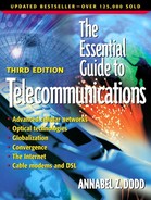
Channel banks, as illustrated in Figure 6.1, are the multiplexing devices that connect digital T-1 circuits to analog private branch exchanges (PBXs) and central office switches. The channel bank takes the signals from analog systems such as older analog PBXs and samples each of a possible 24 analog voice or data streams 8000 times each second. It digitizes these voice and data connections and sends them down the digital channel. At the receiving end of the T-1 circuit, the channel bank decodes digital signals back to analog. The methodology used for sampling and coding these signals is pulse code modulation (PCM). Decoders within the channel bank perform coding and decoding functions of converting analog voice to digital, and vice versa. All new PBXs, central office switches and most key systems are digital and channel banks are not required for T-1 connections.
Figure 6.1. Using a channel bank so that a T-1 circuit can be shared for voice and data.
DS-0 and DS-1—64,000 or 56,000 vs. 1,544,000 bps
The speed of a T-1 circuit is 1.54 million bits per second. The letters “DS” stand for digital signal level. DS-0 refers to the 56-Kbps or 64-Kbps speed of each of the 24 individual channels of the T-1 or E-1 circuit. DS-1 refers to the entire 1.54-megabit T-1 line. The terms DS-1 and T-1 are used interchangeably. An entire T-1 or single digital DS-0 line with a speed of 64-Kbps can be purchased. Fractional T-1 service, which is made up of more than one but less than 24 channels of the T-1 circuit, is covered below.
DS-0 = 64,000 bps
DS-1 = 1,544,000 bps
Often, organizations want digital connections between their locations, but they don't have enough traffic to warrant paying for a full T-1 line. For example, a T-1 circuit between New York City and Boston costs about $5000 per month. A 56,000-bps DS-0 line might cost only $800 monthly. A publishing organization in Boston with a sales/marketing office in New York has a single 56,000-bps line connecting the two offices. The line is used primarily for transmission of email and sales proposals between the two sites, and the 56-Kbps capacity is sufficient.
Clear Channel Signaling
All DS-0s run at 64,000 bps. However, depending on the signaling available in the telephone company's network, 8000 of the bits might be required for signaling and maintenance functions, leaving only 56 Kbps for user data. Clear channel signaling must be available with the chosen carrier to be able to use the full 64 Kbps for user data. With clear channel signaling, the 8000 bits don't have to be “robbed” for network maintenance. Thus, the full 64,000 bits are available for user data.
The total bandwidth of a T-1 circuit is higher than the sum of all of the channels—24 × 64,000, which equals 1,536,000. The extra 8000 bits (1,544,000 – 1,536,000 = 8000) are used for synchronization, keeping the timing set between frames. A frame is a grouping of bits with samples of data from each of the 24 channels. Data from devices connected to the T-1 are sampled, put into frames and sent sequentially on the T-1 line.
Media Used for T-1 Signals
T-1 can be installed on a variety of media, including the following:
Fiber optics
Twisted pair
Coaxial cabling
Microwave
Infrared light
In the 1980s, when T-1 was first used by large corporations, the medium it was installed on was mainly twisted pair copper. When T-1 circuits are run over twisted pair, two pairs (four wires) are used. One pair is used for transmitting and one pair for receiving. Telephone companies that used T-1 in its early days (the 1960s and 1970s) used a combination of coaxial cables, twisted pair and microwave media. Microwave works well for hard-to-cable areas such as the Grand Canyon.
As fiber optic cabling became available in the 1980s, its lightweight, high-capacity and low-maintenance characteristics made it a good choice for telephone companies. Local phone companies often bring fiber directly into users' premises when they install T-1 circuits. When fiber is brought into a user's premise, the end user must supply the electricity for the equipment that converts the signals between electrical pulses for internal copper cabling and light pulses for the outside telephone company fiber. If there is no backup power, customers lose their T-1s when they lose power.
European vs. American and Japanese T-1—24 vs. 30 Channels
The only digital signal speed that is standard throughout the world is the DS-0 speed of 64 kilobits. There are two standard DS-1 speeds: The U.S., Canada and Japan use 1.544 for T-1 with 24 channels, while the rest of the world uses 2.048 with 32 channels—30 channels for user data, one channel for signaling and a channel for framing and remote maintenance (see Table 6.2). People who want to run a T-1 from the U.S. to an office in Europe need rate adaptation equipment so that the carrier in the U.S. can connect the domestic T-1 to the European T-1 line. T-3 speeds also are different in North America, Japan and Europe. DS-0, DS-1 and DS-3 are the most prevalent T carrier speeds. Some people refer to European speeds as E1, E3, and so forth, and Japanese speeds as J-1, J-2 and so forth.
| Level | North America | Japan | Europe | |||
|---|---|---|---|---|---|---|
| User Channels | Speed | User Channels | Speed | User Channels | Speed | |
| DS-0 | 1 | 64 Kb | 1 | 64 Kb | 1 | 64 Kb |
| T-1 (DS-1) | 24 | 1.544 Mb | 24 | 1.544 Mb | 30 | 2.048 Mb |
| T-2 (DS-2) | 96 | 6.312 Mb | 96 | 6.312 Mb | 120 | 8.448 Mb |
| T-3 (DS-3) | 672 | 44.7 Mb | 480 | 32.06 Mb | 480 | 34.368 Mb |
| T-4 (DS-4) | 4032 | 274.17 Mb | 5760 | 400.4 Mb | 1920 | 139.3 Mb |
Speeds higher than DS-3 are called optical carrier (OC) in North America, and synchronous transfer mode (STM) in Europe. See section on SONET later in this chapter.
A Sampling of T-1 Configurations Using T-1 for Combining Voice, Fax, Video and Data
To save costs on wide area networks (WANs), organizations combine voice, fax, video and data over T-1 circuits. The voice lines usually are connected to a PBX and the data is sent to the LAN. An option for these connections is to terminate the T-1 in a drop-and-insert multiplexer. The drop-and-insert multiplexer drops off some channels of the T-1 to data devices. It then “stuffs” bits into the channels it dropped off to the data devices and sends a full T-1, including the “bit-stuffed” channels to the PBX's T-1 multiplexing equipment. See Figure 6.2 for a visual depiction of the drop-and-insert concept.
Figure 6.2. A drop-and-insert multiplexer with a digital PBX, so voice, data and video can share a T-1 circuit.

Digital Cross Connects—Flexible Capacity
Digital cross connect services are commonly used in organizations that have multiple sites they want to connect with private, dedicated lines. T-1 service often is used for dedicated lines for the exclusive, full-time use of organizations. (See Chapter 5.) If a firm needs a full T-1 at headquarters but partial T-1s at its remote sites, one option is to use digital cross connections. With digital cross connects, the network service provider runs a full T-1 from its telephone switch to the organization's headquarters. The carrier divides up 24 channels between the customer's other locations, as shown in Figure 6.3.
Figure 6.3. Digital cross connect switching used in a four-site WAN—wide area network. The digital cross connect enables the headquarters to change the configuration to, for example, 8 lines to Site A and 10 lines to Site C if traffic patterns change.

Some carriers provide customers the capability to reconfigure their T-1 channels from a terminal or PC at the customer's location. This is useful for applications such as rerouting traffic in the event of a disaster or time-of-day peaks in data communications traffic.
Fractional T-1—When 24 Paths Are Not Required
Customers who require more than 64 Kbps, but less than a full 1.54 megabit T-1, often opt for fractional T-1. Fractional T-1 is sold at speeds of less than full T-1, for example 256, 512 and 768 kilobits per second. Four channels at 256 Kbps (4 × 64 = 256 Kbps) cost less than 1.544 megabits. Some ISPs offer Internet access at fractional T-1 speeds of, for instance, 768,000 bits per second. This is equivalent to 12 DS-0 channels or half of a T-1. This is a lower cost option for small and medium-sized firms than full T-1 access.
Fractional T-1 services are available in increments of two channels starting at 128 Kbps (2 × 64). Customers don't purchase fractional T-1 at higher than eight or twelve DS-0 channels because the price becomes equivalent to the cost of a full T-1. Fractional T-3, E-1 and E-3 service is sold as well.
T-3—The Capacity of 28 T-1 Lines, 672 Channels
A T-3 circuit is equivalent to 28 T-1s, or 672 channels (28 × 24 = 672). The total speed of a T-3 line is 44.736 megabits per second. This speed is higher than 28 × 1.544 because some bits are needed for overhead (i.e., signaling and maintenance).
Large call centers often require several T-1 circuits at a single location. Rather than install multiple T-1s, companies install T-3 circuits. T-3 services start to cost less than multiple T-1s when customers have between eight to ten T-1s at the same site. Catalog sales, financial institutions, insurance companies and service bureaus that provide call center functions for smaller companies are examples of call centers that might require T-3 capacity.
Fortune 100 companies use T-3 service to carry voice, video and data traffic on private lines connecting their largest sites.
Internet service providers and telephone companies utilize the 672-channel capacity of T-3. Large ISPs use T-3 to connect their switches to the Internet backbone. They also provide T-3 service as a point where customers access their network. For example, customers call into the T-3 network entrance points from individual 56 Kbps to 1.54 T-1 lines. Many telephone carriers and Internet service providers are upgrading from T-3 to optical carrier-level service in their backbone networks.
An Explanation of Time Division Multiplexing and Its Limitations
All T carrier signals (e.g., T-1, E-1, E-3 and T-3) are based on time division multiplexing. Each device that communicates over a T-1 line is assigned a time slot. If there are eight telephones contending for a T-1 circuit, a time slot is saved for each telephone for the duration of the particular telephone call. For example, telephone 1 might be assigned slot A; telephone 2, slot B and so forth. Similarly, if PCs use the T-1, PC 1 is assigned time slot A, PC 2 is assigned time slot B and so forth. If a PC pauses and does not send for a few minutes, the slot is not assigned to another computer. The assigned time slot is transmitted without any bits. This is why time division multiplexing is not an efficient way to use a wide area network. Pauses in data transmission result in idle time slots. In a network with millions of time slots, this can result in many idle time slots and wasted bandwidth (see Figure 6.4). Incumbent local telephone companies' networks around the world use T-3 and E-3 to transmit traffic between tandem central offices.
Figure 6.4. Time slots wasted in a time division multiplexing circuit.

Newer transmission techniques such as ATM and IP do not assign specific time slots to each device. Rather, only transmitted bits use bandwidth. This results in a more efficient use of transmission capacity. (See the end of this chapter for ATM.)