Network Intelligence and Signaling
Signals in public networks are used for billing, monitoring, links to advanced features and for carriers to exchange traffic with each other. The public network owes much of its reliability, advanced features and interoperability to signaling.
Overview of Signaling
Signaling is used to process every switched call on the public switched network and the public cellular network. The caller dials a number and hears progress tones such as dial tone, ringing, busy signals or reorder tones. These are all signaling tones carried within the public network. In addition to tones, callers might hear digital messages telling them the number they dialed is not in service or has been changed.
Signaling innovations represent a major improvement in the public network's capabilities. They not only enable carriers to manage their networks more efficiently, but they also provide the means for the introduction of profitable, new services.
Signaling innovations led to:
Cost reductions and cost stabilization in the price of long distance.
A platform for new, network-based services such as fax-on-demand, prepaid calling cards and voice mail.
Toll-free 800, 877 and 888 number portability between carriers (the ability for an organization to retain its toll-free numbers when changing carriers).
Local number portability, which allows users to keep their telephone number when they change telephone provider.
Improved network reliability.
ISDN Integrated services digital network is a way to carry 2 or 23 voice and data channels over the same cables. The signals are carried in a separate channel on the same cable.
Lucrative “smart” services such as caller ID, call trace, call return and call waiting.
In addition, signaling is the backbone for interconnection between cellular, global wireless and multiple carriers' networks. The architecture of the signaling network was established by AT&T in conjunction with Bell Labs in the l970s. Prior to the 1984 divestiture, AT&T owned all of the 22 Bell Operating Companies (BOCs). It had the necessary control of the public network that enabled it to set a standard that was followed across the country and later adopted by the international community.
A new way to carry signals such as ringing, dialing and disconnects was developed by AT&T in the 1970s, resulting in increased efficiency, automation and functionality. The new signaling, known as common channel interoffice signaling, carries signals on a separate data communications network rather than on the same path as a person's voice. Out-of-band signals are faster than in-band signals and use less network time for nonbillable call setup.
Background
Common channel interoffice signaling, also known as out-of-band signaling, is in reality a data communications network laid over carriers' switching networks. It has opened markets for new products and enhancements to carriers' features. Common channel signaling was developed as a way to increase network efficiency by setting up separate channels for signals. It evolved into the basis for intelligent networks. Routing instructions, database information and specialized programs are stored in computers in the carriers' networks and are accessible over out-of-band signaling links.
Beginning in the late 1970s, the public network evolved from purely carrying voice and data calls to a vehicle with intelligence, greater capacity and faster recovery from equipment failure. The impetus to upgrade the network came from AT&T's desire to manage and add capacity to the network more cost-effectively. This upgrade laid the foundation for new services such as enhanced 800 services, prepaid calling cards, roaming in cellular networks, ISDN, call forwarding, three-way calling and call waiting.
Signaling System 7 (SS7)—Lowering Costs and Increasing the Reliability of Public Networks
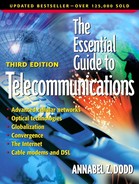
The Signaling System 7 (SS7) protocol, which is based on common channel signaling, is a factor in lowering barriers to entry into the common carrier market. Routing intelligence is located in lower cost computer-based peripherals rather than in central office switches. For example, powerful parallel processing computers hold massive databases with information such as routing instructions for toll-free and 900 calls. One processor with its database supports multiple central office switches. (See Figure 5.15.) In this case, each central office switch is not required to maintain sophisticated routing information. The expense of the upgrade is shared among many central offices.
Figure 5.15. Common channel signaling.

The significance of advancements in signaling technology should not be underestimated. When network problems are detected, alerts are sent over the signaling network to centralized network operation centers (NOCs) where technicians see visual indications of alarms on wall-mounted, computerized displays. Moreover, sections of carrier networks can be quickly reconfigured from commands sent by centralized network control centers over signaling channels. Immediately after the 1989 earthquake in California, the network was reconfigured such that no calls were allowed into California. This left paths open for Californians to make calls out of the state to reassure relatives that they were safe.
Adding Features to Carriers' Networks
Specialized servers and central office switches communicate with each other over out-of-band signaling links. For example, databases located in carriers' public networks are capable of storing the profiles of both the telephone number dialed and the telephone number of the caller for each call. This intelligence enables firms to customize call treatment. For example, from 8:00 a.m. to 5:00 p.m. Eastern Standard Time, 800 calls may be routed to a firm's east coast call center. After 5:00 p.m. Eastern Standard Time, all calls may be routed to California.
Because the databases and specialized processors are on separate computers from the central office switch, the central office and its switch do not have to be upgraded each time new “intelligence” is added to the network. This is a significant factor in allowing faster additions of features to the public network. In addition, multiple central offices access the specialized servers and databases. Thus, adding upgrades through the signaling network provides additional functionality to multiple central offices.
Examples of features available on networks with common channel signaling include:
Voice-activated dialing for calling cards, car phones and home phone lines supported by speech recognition systems in the network.
Custom-calling features from local telephone companies such as call forwarding, call conferencing and call waiting.
Load balancing by call volume (e.g., 50% of the calls sent to California and 50% to the call center in Iowa).
Calling number and calling name delivery (display of the calling telephone number and name associated with the telephone placing the call).
Customer links to carrier networks, where customers specify new call destinations for the 800 services into their call centers. For example, calls may be redirected based on unusual traffic patterns.
Cellular networks use SS7 technology for roaming service as well as for the traditional routing and tracking of calls used by landline networks. Every cellular provider has a database called the home location register (HLR) where complete information is kept for each subscriber. They also have a visitor location register (VLR), which keeps temporary records for callers who are visiting from other areas. When a cellular subscriber roams, each visited system exchanges SS7 messages with the “home” system. The home system also marks its home location register so it knows where to send calls for its customers that are roaming.
As cellular providers upgrade their networks to support higher data rates and more capacity, new signaling services will need to be implemented. For example, general packet radio services (GPRS), which is being planned for higher speed data services, requires GPRS Roaming Exchange. GPRS Roaming Exchange standardizes addressing, security and call routing between networks.
Residential, business and cellular voice mail purchased from local telephone companies are examples of services made possible by common channel signaling. Single voice mail systems manufactured by vendors such as Lucent and Comverse Technology support multiple central offices. Following are some of the messages communicated between network-located voice mail and central office switches (see Figure 5.16):
Initiate stutter dial tone or light message-waiting indicators to tell users they have voice mail messages
Instruct the voice mail system as to which person should receive specific voice messages (e.g., play Mr. Smith's greeting for this call)
Turn stutter dial tone and message-waiting indicators off when voice mail messages have been listened to
Figure 5.16. Central office links to voice mail.

Common Channel Signaling, Efficiency and Redundancy
SS7 is a separate data network that carries all of the signaling in each carrier's network. The efficiency of common channel signaling is achieved by having one signaling link support multiple voice and data transmissions. The fact that one signaling link supports many trunks (high-speed links between telephone switches) highlights the requirement for reliability. If one signaling link crashes, many trunks are out of service. Redundancy is an important consideration in the design of carriers' signaling networks. (See Figure 5.16 for an illustration of redundant signaling links.)
Signaling System 7—The Glue for Links Between Carriers
A major value of Signaling System 7 (SS7) is its capability to enable all carriers to work in concert with each other. It is a standard protocol approved by the International Telecommunications Union (ITU). Signals are sent between central office, interexchange carriers, international phone companies and to specialized processors and databases. Global billing, toll free and 900 services and international roaming for wireless calls all are dependent on SS7.
Early SS7 ImplementationsThe Swedish PTT trialed SS7 in 1983. The United Kingdom and France also had early implementations in the early 1980s. MCI (now part of WorldCom) first implemented SS7 in its network in April 1988 in Los Angeles and Philadelphia. According to a May 2, 1988 article in Network World, MCI stated that it had halved call setup time on calls over the Philadelphia/Los Angeles route. Freeing up voice paths from signaling enabled carriers to pack more calls on their existing network paths. |
The precursor to SS7, Signaling System 6 (SS6), was developed by AT&T in the 1970s for the old Bell system. AT&T took advantage of computer-controlled switching to develop an overlay signaling network. In essence, it created a data communications network that could send more complex messages than the limited in-band tones that notified the network when calls were completed, how they were addressed, and so forth. The first implementation of Signaling System 6 in 1976 by AT&T was automation of calling card validation. SS6 enabled AT&T to eliminate operators for calling card validation.
With common channel interoffice signaling (CCIS), authorization for calling card calls is done automatically by checking the telephone company databases, called line information databases (LIDBs). Line information databases contain all valid telephone and calling card numbers. An operator is not required to check a computer database to determine if the calling card number is valid. Instead, the central office sees from the number dialed that the call was made from a calling card. It then initiates a call to the LIDB to determine the validity of the calling card.
AT&T mandated the implementation of Signaling System 6 throughout the entire Bell system in the late 1970s. The faster SS7, a layered protocol with signaling links of 64,000 bps, was specified by AT&T in 1980. SS7 now supports 1.54 megabit per second signaling links. SS7 is used, with variations, on a global basis.
As with many standards, implementation of SS7 differs among countries. For example, the U.S., Canada, Japan and parts of China implemented the American National Standards Institute (ANSI) version of SS7. Europe implemented the European Telecommunications Standards Institute (ETSI) version. Parts of the world also use an International Telecommunications Union (ITU) version of SS7.
Gateways translate these various SS7 protocols so that international carriers can understand each other's signaling. This enables central office switches to communicate, for instance, with Chinese and European SS7 implementations.
SS7 Components
SS7 components include:
Packet switches, or signal transfer points that route signals between databases and central offices
Service switching points, software and ports in central offices that enable switches to query databases
Service control points, specialized databases with billing and customer feature information
See Figure 5.17 for an overview of the following SS7 components. Not all carriers own and operate their SS7 networks. They may, for example, use SS7 networks from companies such as Illuminet. Carriers that use Illuminet have links from their central office to the Illuminet signal transfer points.
Figure 5.17. SS7 components.

Signal Transfer Points (STPs)
Signal transfer points are packet switches that route signals between central offices and specialized databases. Messages are sent between points on the SS7 network in variable-length packets with addresses attached. (Think of the packets as envelopes of data containing user information such as the called and calling telephone number, error correction information and sequencing numbers so that the correct packets or envelopes are grouped together in the correct order at the receiving end.) Signal transfer switches read only the address portion of the packets and forward the messages accordingly.
The fact that the signals are sent in a packet format is a significant factor in SS7's efficiency. Packets associated with multiple calls share the same pipe. Packets from transmissions a, b, c, and so forth are broken into small chunks (packets) and sent down over the same 64 or 1540 kilobit SS7 links and reassembled at the destination.
Service Switching Points (SSPs)
Service switching points enable central offices to initiate queries to databases and specialized computers. Service switching points consist of software capable of sending specialized messages to databases and ports connected to the S77 network. For example, when a 900 call is dialed, SSPs set up a special query to a 900 database (the service control point) for information on routing the call.
Service switching points convert the central office query from the central office “machine language” to SS7 language. When signals are received from the signaling network, the service switching points convert the SS7 language to language readable by the central office switch.
Service Control Points (SCPs)
Service control points hold specialized databases with routing instructions for each call based on the calling party and/or the called party. For example, service control points tell the network which carrier to route an 800 call to. Services such as network-based voice mail, fax applications and voice-activated dialing are located on service control points or intelligent peripherals.