LANs, MANs and WANs
The difference between LANs, MANs and WANs is the distance over which devices can communicate with others. See Table 1.4. As the name implies, a local area network is local in nature. It is owned by one organization and is located in a limited geographic area, usually a single building. In larger organizations, LANs can be linked together within a complex of buildings on a campus. Devices such as computers linked together within a city or metropolitan area are part of a metropolitan area network (MAN). Similarly, devices that are linked together between cities are part of a wide area network (WAN).
| Term | Definition |
|---|---|
| LAN (Local Area Network) | A group of devices, such as computers, printers and scanners, that can communicate with each other within a limited geographic area such as a floor, department or small cluster of buildings. |
| MAN (Metropolitan Area Network) | A group of data devices, such as LANs, that can communicate with each other within a city or a large campus area covering many city blocks. |
| WAN (Wide Area Network) | A group of data devices, usually LANs, that can communicate with each other from multiple cities. |
| Hub | The intelligent wiring center to which all devices, printers, scanners, PCs and so forth are connected within a segment of a LAN. Hubs enable LANs to be connected to twisted pair cabling instead of coaxial cable. Only one device at a time can transmit via a hub. Hubs provide a point for troubleshooting and relocating devices. Speed is usually 10 Mbps. |
| Backbone | Wiring running from floor to floor in single buildings and from building to building within campuses. A backbone connects to hubs or switches located in wiring closets on each floor. |
| Bridge | Bridges usually connect LANs using the same type of protocol together. They have limited intelligence and generally only connect a few LANs together. Bridges were in limited use as of the early 1990s when the price of routers dropped. Layer 2 switches also have replaced bridges. |
| Layer 2 switch (also called switching hub) | Layer 2 switches are bridges that allow multiple simultaneous transmissions within a single LAN. Total speeds range from 10 Mbps to 100 Mbps (megabits per second). Layer 2 switches provide a dedicated connection during an entire transmission. |
| Layer 3 switch (also known as routing switch) | Layer 3 switches have the capability to route traffic across the LAN backbone. They are used to connect wiring closets and buildings within a campus. This is typically the LAN backbone. |
| Router | Routers connect multiple LANs. They are more complex than bridges and can handle a greater number of protocols and LANs. Routers select the best available path over which to send data between LANs. New routers do not look up each packet's address in the CPU's memory. Routing is done in chips on each module or card. |
| Server | A centrally located computer with common departmental or organizational files, such as personnel records, sales data, price lists, student information and medical records. Servers connect to a hub or a Layer 2 or 3 switch. Access to servers can be restricted to authorized users only. |
LANs—Local Area Networks
LANs are used to communicate within a limited area such as a building or campus. Examples of devices within LANs are: shared printers, PCs, alarm devices, factory automation gear, quality control systems, shared databases, factory and retail scanners and security monitors (see Figure 1.6). A discrete LAN is typically located on the same floor or within the same department of an organization.
Figure 1.6. A local area network.

LANs grew out of the proliferation of PCs. Once people had PCs on their desktops, the next step was to connect these PCs together. LANs first appeared in 1980. The initial impetus for tying PCs together was to share costly peripherals such as high-speed printers. LANs are the building blocks for connecting multiple locations together for the purpose of sending email and sharing databases and applications with remote locations and telecommuters. These email and corporate information files are located in specialized computers called file servers. Access to file servers can be limited by password to only approved users.
The software that runs local networks is called LAN network operating systems and is located on servers connected to the LAN. Most operating systems in use today are built on the client-server model. Clients (PCs) request services such as printing and access to databases. Applications such as print and fax servers run access to services (e.g., printers and databases). The network operating system controls access to the LAN where resources such as files, printers and modems are located. Microsoft NT and Novell NetWare are client-server-based LAN network operating systems.
Each device connected to the local area network can communicate with every other device. The connections between devices may be any of the following: twisted pair, coaxial cable, fiber optics or wireless media. For the most part, devices are connected to a LAN by twisted pair cabling that is similar to but sometimes of a higher quality than that used to tie business telephones together. (Media options are covered in Chapter 2.)
When local area networks became popular in the 1980s, many individual departments purchased their own LANs independent of the central computer operations staff. As the need arose to tie these LANs together for email and file sharing, compatibility between LANs from different manufacturers became a problem. The TCP/IP suite of protocols became a popular choice for overcoming these incompatibilities. Devices called bridges and routers were developed to send data between LANs.
LAN and WAN Devices
New LAN and WAN gear are being developed to handle increases in traffic in carrier and enterprise networks. Lower prices for some of this equipment is making LANs feasible for small businesses and residences.
Server Farms and Multimedia—High-Bandwidth Applications
Original LAN designs lent themselves to “bursty” traffic such as brief email and text messages. Not only are new applications adding traffic to LANs, but the traffic is no longer the short, bursty type with pauses that give other devices a chance to transmit. The fact that the world is more networked is causing huge increases in corporate bandwidth requirements. People are typically sending PowerPoint® attachments with 6 to 16 million bytes between companies. Server farms are centralized locations in corporations' or carriers' networks with groups of servers containing enterprises databases or Web pages. Downloads from server farms are often long, continuous streams of images, audio and video files. In addition, more organizations are connecting applications such as voice mail, call centers and IP-based telephone systems to LANs. (See Chapter 2 for unified messaging, call centers and IP-based telephone systems.)
More Powerful PCs
In addition to applications that require large amounts of data to be transmitted on LANs, more powerful PCs impact LAN requirements. In the 1980s when LANs were first implemented, people had computers with 286 chips on their desks with small amounts of memory and hard disks. In recent years, staffs have Pentium computers with 132 megabytes of memory and gigabyte-sized hard drives. These robust PCs have multimedia capability. This enables them to participate in desktop videoconferences, download large files from the Internet and share large JPEG files. All of this traffic is carried over the LAN.
Hubs
Hubs enable devices on LANs to be linked together by twisted pair copper wire instead of the heavier, thicker coaxial cable typically used in the cable TV industry. When LANs were initially implemented, they were installed using coaxial cable to interconnect devices on the LAN. Coaxial cable is expensive to install and move. It is not unusual in large organizations for entire departments and individuals to move at least once a year. The use of coaxial cabling resulted in a loss of space in dropped ceilings and conduit for the cable.
With a hub, instead of wiring devices to each other, each node or device is wired back to the hub in a star pattern. Using a hub changes the topology of a LAN. The hub creates a star design, or topology. (Topology is “the view from above”—in the case of hubs, a star where each device is connected to a central device.) Without a hub, each device in a LAN is wired to another device in a “bus” arrangement. In the bus topology, if one device is taken out of the line or bus, or if there is a break in the line, each device is affected. By employing a hub, a device can be moved or taken out of service if it is defective without affecting other devices on the LAN. A hub is kept in the wiring closet of each floor within a building, as shown in Figure 1.7.
Figure 1.7. Top: LAN with a hub to link devices with twisted pair wiring. Bottom: LAN without a hub.
Layer 2 switches are replacing hubs because of hubs' limitations. Only one device at a time can communicate on hub equipped LANs, and speeds are limited to 10 megabits per second. Moreover, hubs are suited to networks with bursty (short in length), messages and LANs now carry more multimedia traffic.
Layer 2 Switches
Layer 2 switches are faster than hubs and provide more bandwidth per device on LANs. Some Layer 2 switches are non-blocking. They have enough capability so that each device can communicate at the same time. For example, a switch capable of forwarding packets at 100 million bits per second would be non-blocking if 10 users were connected to the switch and each needed 10 million packets per second of capacity.
When LANs were first implemented, in addition to assumptions regarding burstiness, it was assumed that applications such as email would not require immediate response. This is not true for newer applications such as unified messaging where users receive voice mail as well as email over the LAN. Delays (latency) are not acceptable when downloading graphics from the World Wide Web or transmitting video and voice on the LAN.
Some Layer 2 switches have cut-through capability, which enables them to start sending frames to their destination as soon as they see the address at the beginning of the frame. They don't have to wait to receive the entire frame before they start sending. A frame is an arrangement of bits in a predefined order that includes addressing, error control, user data and bits that mark the end of the frame. Layer 2 switches are located either in work groups where they are connected to a group of ten or so users or in wiring closets serving a few hundred users. The number of nodes connected to a switch depends on the switch's speed and the users' requirements.
Layer 3 Switches—Also Known as Switching Routers
A Layer 3 switch has connections to multiple Layer 2 switches and has routing capability. It generally is located in wiring closets (connecting hundreds of users) or LAN backbones (connecting many wiring closets or buildings together). Some enterprises install Layer 3 switches to replace routers within the LAN or campus. However, they usually keep their router to connect to the Internet and to WANs because routers have more sophisticated WAN protocols and hardware for connections to services such as Frame Relay and T-1. (See Chapter 6 for T-1 and Frame Relay.)
Layer 3 switches are faster and less complex to install than routers. Each port only needs to be programmed with information on the identity of the user connected to the port and what level of priority to assign the port.
Switches support Ethernet, Fast Ethernet and Gigabit Ethernet. Ten-Gigabit Ethernet standards are being developed.
Bridges
Bridges became available in the 1980s as a way to connect a small number of LANs together. Bridges provide one common path over which multiple LANs may be connected together (see Figure 1.8). For example, if an organization has two locations in different cities that need to exchange data, a bridge can be used. Bridges also are used as a way to cut down LAN congestion. The bridge can connect two different departments so that each departmental LAN is not congested with intradepartmental traffic. Bridges most often connect two LANs with like protocols such as an Ethernet LAN to an Ethernet LAN. There are more sophisticated bridges that connect an IBM token ring network to an Ethernet LAN.
Figure 1.8. A bridge connecting two local area networks.

Bridges are easy to configure because there are a limited number of choices in configuring them. Each piece of data sent via a bridge takes the same path and is sent to every device on the network. The lack of routing and congestion control puts bridges at Layer 2 in the OSI model. Only the device to which the message is addressed takes the message off the network. This broadcast feature of bridges can choke the network with too many messages, slowing down the network for everyone. As LANs proliferated and router prices dropped, people turned to routers and then switches rather than bridges.
Routers
Routers connect multiple local area networks. They also connect LANs to the Internet and to wide area networks. These LAN connections are usually between LANs located in distant buildings on a campus or in different buildings in diverse cities. Routers in carriers' networks pick the least congested paths over which to forward packets. To illustrate a user may send two messages from Chicago to Los Angeles. The first message might route via Alaska and the second via Texas. Because of congestion and routing, the second message might arrive before the first one. Routers are more sophisticated and have additional capabilities not available in bridges. A major advantage of routers is their capability to forward differing protocols from varied departmental local area networks. It is important to note that routers do not translate application protocols. A UNIX computer cannot read a Microsoft Windows word processing document. The router merely transports differing LAN protocols in corporate and carrier networks.
Router capabilities include:
Flow control— If the path the data takes is congested, the router can hold the data until capacity is available on the path between the routers.
Path optimization— The sending router selects the best available path by checking routing tables contained within the router.
Sequencing— Routers send data in packets, or envelopes. These packets might arrive out of order at the destination router. From information in the packet, the receiving router knows the correct order and arranges the data accordingly.
Receipt acknowledgment— The receiving router sends a message to the router that sent the message acknowledging that the data was received correctly.
Intelligence inherent in routers leads to two major disadvantages: First, routers are complex to install and to maintain. Every router in an organization's network must have up-to-date address tables. Each device on a LAN is called a node and has an address. For example, if a printer or PC is moved from one LAN to another, the router table must be updated or messages will not reach that device. To illustrate the complexity of managing routers, it is common to hear of consultants with full-time contracts for updating router tables for organizations. Second, routers are slower than bridges. The need to look up tables within the router slows down the router's speed. The functions of congestion control, routing, sequencing and receipt acknowledgment make routers network Layer 3 devices.
Home LANs—Sharing Printers and High-Speed Internet Access—A Lack of Technical Support
People with home-based businesses and school-aged children often have multiple computers. Multiple computers per residence is not uncommon. According to International Data Corporation statistics quoted in an article titled “Home Networking,” published in The Boston Globe, page C2, 12 December 2000, by Hiawatha Bray, 13% of American homes have more than one computer. International Data Corporation predicts that by 2004, 28% of homes will have more than one computer. Many of these consumers have high-speed DSL or cable modem access to the Internet that they wish to use for all their computers. They also share laser or color printers among their computers.
Although often slower and less complex, home networks are created along the same line as corporate networks. Hubs are required to share devices and routers are used to give all PCs access to high-speed telephone lines. The PCs, hub, printers and scanners are connected together wirelessly or by data grade (usually category 5), unshielded twisted pair cabling. (See Chapter 2 for media.) To share a printer, users need an inexpensive hub in which to plug their printer and each of their computers. Each computer connected to the LAN needs an Ethernet card connected to the hub or if the computer is in another room, an RJ-45 data jack connected by unshielded twisted pair cabling to the hub. RJ-45 jacks are similar to jacks that analog phones plug into except that they have four wires (two pair) instead of one pair needed for the phone jack.
To share high-speed DSL or cable modem service, the hub is connected to a router that plugs into the modem. Devices that combine hub and router functions in one “box” are available from vendors such as LinkSys, 3Com, NETGEAR and Xsense (for Macintosh computers). (See Figure 1.9.) In addition to cabling to connect routers and hubs, computer software needs to be added for work on home LANs to operate.
Figure 1.9. Home LANs.

The issue of customer support is a major stumbling block to implementation of home networks. Most carriers that sell high-speed Internet access to consumers do not provide telephone support for routers. Some are concerned that home LANs will generate too much traffic and are considering charging higher fees to customers with more than one computer. Customers get support from router companies, friends and MIS staff where they work.
Wireless LANs for Homes and Small Businesses
For customers who don't want the expense and trouble of running unshielded twisted pair cabling to each computer, wireless LANs are an option. With a wireless LAN, laptop computers can be used in any room of the house within range of the wireless antenna. Most systems support devices located about 150 to 200 feet from the transmitter. Moreover, as more devices such as games and appliances are networked, they can be more easily added wirelessly than with cabling. The most prevalent wireless standard is based on 802.11b and is called Wi-Fi. Apple's 802.11b wireless product is called Airport.
Both Macintosh- and Windows-based computers need a radio card added to them. On Windows laptops, the radio card currently uses the PCMCIA slot on the side of the laptop. The PCMCIA slot is not required for new Macintosh laptops because their wireless interface is installed internally. Windows-based laptops are expected to follow suit shortly. In addition, an external base station equipped with a transmitter is plugged into the DSL or cable modem. Each computer communicates wirelessly with the transmitter. Agere Systems (formerly part of Lucent), 3Com, LinkSys and Apple all sell wireless home networks. As with wired home and small office networks, setting up the software is complex in some of these systems.
MANs—Metropolitan Area Networks
Metropolitan area networks, or MANs are connections between local area networks, within a city or over a campus. Campus MANs are spread out over many blocks of a city. Examples of MANs are those of large hospitals and university complexes. For example, a hospital in downtown Boston keeps its x-rays and other records in a nearby section of the city. Instead of trucking records and x-rays between the two sites, the hospital leases high-capacity telephone lines to transmit records and images. The connections between these two sites are metropolitan area network connections. These connections can be leased from a telephone company or constructed by the organization. They can be fiber optic, copper or microwave-based services. They also include the same services mentioned for WANs, such as ISDN and T-1.
WANs—Wide Area Networks
The term WAN refers to connections between locations over long distances via telephone lines. For example, a warehouse in Alabama connected to a sales office in Massachusetts by a T-1 line is a wide area network (WAN) connection. In contrast to a local area network, a WAN is not contained within a limited geographical location. The variety of WAN connections available is complex. Selection of an appropriate WAN service depends on the amount of traffic between locations, quality of service needed, price and compatibility with the organization's computer systems. WAN technologies and WAN vendors are reviewed in Chapters 6. These include ISDN, T-1, T-3, ATM and Frame Relay.
Instead of complex WANs, many organizations now have high-speed connections either to the Internet or to carriers instead of directly to other corporate locations. Carriers manage the security and transmission of their customers' telecommunications in virtual private network (VPN) arrangements. (See Chapter 5 for VPNs.)
Higher Speed Services for LAN Traffic
The following protocols are being used to transmit multimedia, engineering and other high-bandwidth LAN traffic.
Fast Ethernet is a shared protocol. However, it has a speed of 100 megabits—10 times the speed of standard 10-megabit Ethernet, the most prevalent LAN protocol. Standard two-pair wiring is used. New cards are required in each PC attached to the LAN.
Gigabit Ethernet works with existing Ethernet LAN protocols. Because of its high speed, 1000 megabits, Gigabit Ethernet requires either fiber optic cabling or Level 6 unshielded twisted pair. On LANs, servers often have direct Gigabit Ethernet connections because of their high-bandwidth requirements. Gigabit Ethernet is used to connect LAN segments to each other within buildings and campuses.
Layer 3 switches are faster than routers used in corporations to connect multiple LANs together on campuses and within buildings. They don't have the router requirement of looking up each packet's address in software.
Fibre Channel protocols are used for gigabit speed, highly reliable short distance access to devices such as disks, graphics equipment, video input/output devices and storage devices that hold massive amounts of data and are often located in server farms. One example of a high-bandwidth application is movie file transfers by movie studios to save time during production. Fewer overhead bits for tasks such as error control and addressing are included in the Fibre Channel Protocol, which uses a device's input/output interface to communicate directly with switches. Enterprise System Connection (ESCON) is another storage-oriented protocol.
Tag switching, supported by Cisco, is a proprietary protocol based on multiprotocol label switching (MPLS) to increase the speed of connections between LANs. In tag switching, bits representing the address are placed in the router's short-term cache memory. A fixed-length tag is added to each packet. With MPLS, short, fixed-length “labels” tell the router how to route each packet so that the router does not have to examine the entire header of each packet after the first point in the carrier's network. The router merely looks at the tag for routing instructions. This shortens the amount of time required to route packets.
New Devices for Carrier and Internet Service Provider Networks
Manufacturers are developing new high-speed routers for the anticipated continued growth in the amount of data versus voice carried in the public network. They envision a network that will carry a preponderance of data, video and audio rather than voice traffic. Data communications equipment manufacturers such as Cisco Systems and Juniper Networks have high-speed routers that they sell to carriers and Internet service providers. They see their equipment as being primarily designed for data traffic but also fast enough to carry voice and video without any degradation in the quality of the voice or video.
Traditional manufacturers of central office equipment designed to carry voice are developing new equipment to carry data more efficiently. These manufacturers include Siemens AG, Lucent Technologies, LM Ericsson and Nortel Networks. All of these organizations have purchased companies that specialize in equipment that can carry high-speed data services. For example, Lucent purchased Yurie Systems and Ascend Communications. Ascend Communications had previously acquired Cascade, a manufacturer of ATM switches, and Stratus. LM Ericsson bought Torrent Networking Technologies and Cisco Systems purchased Cerent Corporation.
Availability vs. ReliabilityWhen carriers purchase telephone company equipment, key criteria for purchases are reliability and availability: Reliability refers to how often a device breaks. Carriers typically require NEBS Level 3 compliance on equipment they purchase. NEBS stands for Network Equipment Building System. Bellcore, (now Telcordia) the former R&D arm of the Regional Bell Operating Companies, developed NEBS standards. The standards include compliance with thermal, electrical, redundancy and earthquake resistance tests. Availability refers to how long it takes to repair equipment, or having the equipment in service even though part of it is not working. For example, if ports are inoperable, the other ports should be available to route calls normally handled by the inoperable ports. In the same vein, backup central processing units (CPUs) should be able to automatically take over if the main CPU goes down. |
Core routing—Terabit Routers
The term terabit router was coined by Avici Systems in 1997. Terabit routers route packets at trillions of bits per second (1,000,000,000,000). Terabit routers generally are geared toward the ISP and carrier market. In planning for and designing their routers, Avici Systems spoke with carriers who stated that they wanted hardware that would be capable of handling the huge amounts of data they expected on the public network from applications such as virtual private networks (VPNs). (See Chapter 5 for VPNs.) They felt that VPNs would be handling a large amount of e-commerce, Extranet and Intranet traffic in the near future. (See Chapter 8 for Extranets and Intranets.)
Avici's terabit routers are computers made on the model of super computers. The switching fabric is made up of up to 560 routers in a single device. If any one of the 560 computers fails, the router still functions and uses the input/output ports associated with the remaining computers. The router uses multiprotocol label switching (MPLS). The smaller headers in MPLS routers enable them to forward packets at high speeds. Avici plans to ship routers at terabit speeds in 2001. One OC-192 equals 10,000 million bits per second of optical carrier (OC) capacity on fiber. 100 OC-192 equals 1 terabit per second. Most new core routers have OC-192 capacity.
Juniper Network core routers are based on Application-Specific Integrated Circuit (ASIC) processors for high performance. ASICs are specialized chips built with the capability of many chips integrated within them. Advances in computers such as memory and connectors have benefited routers that need to check addresses and forward packets at consistently high speeds. For example, the Juniper routers have separate CPUs to select routes and to do the actual forwarding of packets. The routing engine (a CPU) looks up routing tables to select the closest, least congested path through the network. The forwarding engine then puts the packet onto the network.
Other manufacturers of high-speed core routers include Pluris, Nortel Networks and Cisco Systems. Startup Hyperchip in Montreal, Canada has announced that it is developing a router capable of petabit speeds. A petabit equals 1 quadrillion bits per second, or 1000 terabits.
Edge Routers
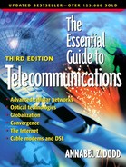
Edge routers connect enterprises to carriers' networks. They are located at the edge of carrier networks. Edge routers aggregate large numbers of relatively slow circuits from end users at speeds such as T-1 (1.54 megabits) and OC-3 (155 megabits) and send them to core routers at speeds of OC-12 (622 megabits) and OC-48 (2.5 gigabits). See Figure 1.10. Connections between core and edge routers are hierarchical in nature, similar to connections between Layer 2 and Layer 3 switches in LANs.
Figure 1.10. Edge and core routers.

Edge routers are slower than core routers. They also provide more services because they connect directly to customers as opposed to core routers that transmit to other core routers and to edge routers. When used by ISPs, edge routers furnish services such as filtering, rate limiting and traffic shaping. Filters are used to block traffic to sites such as pornography, Napster and Internet sites of ISP customers who don't want their employees to use the Internet for personal use. With rate limiting, an ISP can equip its router with T-3, 44.5 megabit ports but allow an access speed of 1.54 megabits per customer. An ISP can sell an aggregate speed of more than 44.5 megabits because it assumes that not everyone will use the service to its full capacity. To illustrate, it might sell 36 T-1s, which equals 55.44 megabits (36 × 1.54), 10.9 megabits more than the port's capacity of 44.5 megabits. Edge routers also provide VPN service. VPN networks furnish security and remote access to enterprise customers. (See Chapter 5 for VPNs.)
Vendors that sell edge routers include Juniper Networks, Cisco and Unisphere.
| Compression Standard | Description |
|---|---|
| MNP 5 | Microcom Network Protocol compression protocol developed by Microcom for modems. Provides 2:1 compression. |
| V.42bis | Data compression protocol for modems. Provides 4:1 compression. |
| H.320 | A family of standards for video adopted by the ITU (International Telecommunications Union). Quality is not as high as proprietary video compression algorithms. Most video codecs employ both proprietary and standard compression algorithms. The proprietary compression is used to transmit to another “like” video unit and the standard algorithm is used when conferencing between differing brands. |
| H.323 | A family of standards for video adopted by the ITU for sending video over packet networks. Microsoft Corporation and Intel Corporation adopted the standard in 1996 for sending voice over packet networks. It is installed on Windows®-based PCs and used to packetize and compress voice when callers with PCs make calls from their computers over the Internet. See Chapter 5. |
| MPEG3 | Moving Picture Experts Group 3 is Layer 3 of MPEG1. It is a compression standard for streaming audio. MPEG3 is the compression algorithm used to download audio files from the Internet. For example, some Internet e-commerce sites allow people with compression software to download samples of music so they can decide if they wish to purchase a particular CD. In addition, people with multimedia computers are playing CDs on their computers or on CD burners and distributing copies to friends without paying royalties. |
| MPEG2 | A Moving Picture Experts Group standard approved in 1993 for coding and decoding video images. MPEG2 uses past images to predict future images and color, and transmits only the changed image. For example, the first in a series of frames is sent in a compressed form. The ensuing frames send only the changes. A frame is a group of bits representing a portion of a picture, text or audio section. |