Optical Networking
New passive optical network (PON) technologies lower the cost of deploying fiber optic cabling in cable TV and landline local access networks. They essentially enable one fiber pair from the network provider's facility to the neighborhood to be shared by many customers. They have the added benefits of lowering the maintenance and operating costs of these networks. Changes can be made by computer commands rather than by dispatching a technician. Passive optical networks also have lower space and power requirements than alternative technologies.
Other optical technologies, optical add and drop multiplexers and optical switches are used in high-speed backbone networks. They lower the cost of bringing high-speed service to medium-sized cities and suburban areas. They also lower the cost of providing redundancy in networks.
Most carriers have routes between the following U.S. cities: Manhattan, Washington, D.C., Atlanta, Miami, Dallas, Chicago, Kansas City, Denver, San Francisco, Sacramento and Los Angeles. These routes are like private lines between carriers' points-of-presence (POPs). The majority of routes using dense wavelength division multiplexers (DWDM) are about 2000 kilometers (km) long (1250 miles) and are built along railroad tracks and other rights-of-ways. Smart optical networking devices let carriers drop off smaller amounts of capacity, single wavelengths or lambdas, to local carriers, ISPs or end-user customers in metropolitan or suburban centers. Optical add and drop multiplexers and optical switches (also referred to as optical cross connects) link fiber rings at large hubs. The fiber rings carry traffic between cities. The hubs connect local traffic to the backbone.
The term lambda comes from the Greek. It is the eleventh letter of the Greek alphabet. Channels of traffic in fiber networks are known as lambdas. They represent one wavelength or stream of traffic in a strand of fiber.
Passive Optical Networks
Passive optical networks (PONs) are devices located in the access network that enable carriers to dynamically allocate capacity on a single strand or pair of fibers to multiple small and medium-sized customers. Access networks comprise the cabling and infrastructure between the customer and the telephone company. The allocation of bandwidth is done through computer control rather than by dispatching a technician when more bandwidth is requested. PONs increase the capacity, flexibility and efficiency of fiber deployed in the last mile, which can cost $2500 to $3000 per building to provision. In addition, the programmability of passive optical network devices enables carriers to manage complex networks more efficiently. Passive optical networking technologies make it cost effective to provide fiber to small and medium-sized businesses. Just as T-1 multiplexers increased the reliability and efficient deployment of copper, passive optical networks do the same for fiber optic cabling in the last mile.
Passive optical networks are lower in cost than digital loop carriers for serving small and medium size customers. They also connect directly to LANs at speeds of one megabit to 100 megabits. With a data connection served by a PON, a customer does not need a DSU/CSU (digital modem) or a T-1 multiplexer. The service connects directly to a router on the customer's premise.
The PON Standard—Carrier Defined
Full Service Access Network (FSAN) is an organization of 21 carriers that has defined the G.983.1 standard for passive optical networks. Carriers in FSAN include British Telecommunications, BellSouth, France Telecom, KPN-Dutch Telecom and SingTel. The standard is based on asynchronous transfer mode (ATM) technology. ATM is a protocol used to aggregate voice and data traffic for transmission across networks. (See Chapter 6.) It is hoped that having a standard will bring down manufacturing costs for PON equipment. PON equipment is sold by companies such as Terawave Communications and Quantum Bridge to network service providers worldwide who are building out fiber networks in metropolitan areas.
PON Technology—Saving Space, Electricity and Costs on Technicians
The equipment consists of a switch that sits at the central office or the cable TV head end called an Optical Line Terminal (OLT). The Optical Line Terminal controls splitters, Optical Network Unit (ONU) and Optical Network Termination (ONT) devices. The Optical Network Termination sits at the customer's premise. See Figure 5.11. The following are an overview of PON devices as defined by FSAN:
The Optical Line Terminal is located at the central office and has multiple cards, each of which supports up to 32 end users. It has ports for the fiber and backup fiber connected to the splitter. It also interfaces to the network service providers' high-speed backbone network.
The splitter is like a garden hose with a T splitter that splits the capacity of the fiber among up to 32 end users.
The Optical Network Unit can be used in cable TV networks or traditional telephone company networks. It converts optical signals to those compatible with coaxial cable and twisted pair. It has interfaces for DSL, cable TV and plain old telephone service (POTS). It brings fiber to the curb or fiber to a neighborhood cabinet.
The Optical Network Termination, which brings fiber to the building, has cards that connect the fiber to customer premise equipment (CPE). These interfaces include T-1 (24 voice and/or data channels) and E-1 (the European version of T-1 with 30 channels) and LAN ports. Twisted pair copper or fiber connections are supported.
Figure 5.11. Passive optical network components. Drawing courtesy of Terawave

Passive vs. Active PON Devices—Low Electrical and Space Requirements Decrease Costs
The term passive in passive optical networks refers to the splitters. The splitters are passive—no electricity is required to operate them. The other devices in PON networks, Optical Line Terminals (OLTs) and Optical Network Terminations (ONTs), are active. They require electricity to operate. The small size of the splitters, about the size of a Personal Digital Assistant (PDA), and the fact that they don't require electricity, lowers the cost of PON service. These are key factors because space in the network is at a premium and electrical costs are soaring.
ASIC High-Speed Processing
Processing speed is critical for Optical Line Terminal (OLT), also called the optical access switch, because it can only communicate with one Optical Network Termination device at a time. Thirty-two devices contend for service from the central office based OLT over fiber links that operate at 155 million bits per second.
Because of this requirement for speed, most PON networks use application-specific integrated circuit (ASIC) chips. An ASIC chip has the whole design of the system burned into the silica on one chip. Because they are “burned” into hardware, they process information faster than field programmable gate array (FPGA) chips. FPGA chips are in software. The up-front design work on ASICs is expensive—it takes 9 to 12 months to develop an ASIC design. However, costs to produce them after the initial design are low.
Passive Optical Network Benefits
Bandwidth can be dynamically allocated through computer commands; customers can call their provider to increase speed on their data services up to 20 megabits for data and three T-1 or E-1 ports for voice or data without the addition of new customer premise equipment. (Greater capacities will be available in later releases.)
One strand of fiber is brought to the neighborhood and multiple strands are run from there. This is particularly cost effective in areas that do not have digital loop carrier equipment or where the DLC equipment is at capacity.
Because of the low cost of the electronics between the carrier-located switch and the customer, redundant routes can be deployed relatively cheaply.
Maintenance of PON equipment is relatively low because technicians can remotely monitor the system all the way out to the Optical Network Termination at customers' premises.
PON equipment can be interfaced with DSL service to make low-cost Internet access available where customers are far from the central office.
Passive optical networks are not suitable for large customers because of the limit of three T-1s or E-1s per Optical Network Termination. There is a particular interest in PONs in Asia where much of the infrastructure is being built from scratch. Carriers in Asian countries are interested in bringing fiber to apartments and small businesses with PON electronics, which are lower cost than SONET. (See Chapter 6.) SONET is used for redundancy and to merge voice and data traffic carried over fiber in carriers' networks.
Optical Add and Drop Multiplexers (OADM)
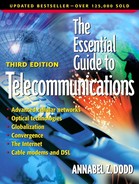
Optical add and drop multiplexers (OADMs) reroute traffic that comes into a carriers' point of presence (POP) from the backbone network. For example, a pair of fibers might carry traffic on 40 different wavelengths. Each wavelength also is called a lambda. Each wavelength (lambda) is essentially a high-speed path of, for example, 10 gigabits per second (Gbps) of data. A filter in an add and drop multiplexer reroutes a single wavelength in the strand of fiber at, for example, the Detroit POP and “drops” it off, or reroutes it to, Cleveland. (See Figure 5.12.) An add and drop multiplexer obviates the need for more expensive amplifiers in Detroit to convert the signal back to an electronic format before sending the traffic to Cleveland.
Figure 5.12. An optical add and drop multiplexer

Optical Cross Connects (OXC)—Optical Switches
Optical cross connect (OXC) systems, (optical switches) have more capability than optical add and drop multiplexers (OADMs). They are used in POPs with higher traffic than those where OADMs are used. They switch light waves in core, high-speed carrier networks. In the future, they may also be used in the backbone, high-traffic portion of metropolitan networks between central office switches. Optical cross connect (OXC) systems let carriers redirect wavelengths through computer commands without physically unplugging fiber optic cables. A technician at a computer can redirect an individual wavelength from one destination to another on the network using software. Demultiplexers in the optical cross connect separate out the wavelengths to their different routes.
The advantages of optical switches are:
Scalability— Optical switches have ports that run at variable speeds. For example, the Tellium, Inc. switch has a capacity for 512 OC 48 (2.48 gigabits) ports or 128 OC 192 (10 gigabits) ports or a mix of the two up to a total of 1.28 terabits per second. Different parts of the network can be equipped with larger or lower amounts of bandwidth.
Reliability: If one route becomes busy, more capacity can be assigned to it by computer command. This is less prone to error than manually plugging and unplugging cables from a fiber patch panel. It is not uncommon for technicians to mistakenly unplug a route with traffic on it. As networks become larger and more complex with more routes, reconfiguring routing needs to be done by computer control.
Less capacity required for service restoration— SONET rings carry traffic in one direction. If the ring malfunctions, the traffic is carried on the backup ring in the reverse direction. Each 10-gigabit segment needs a 10-gigabit segment for backup. Thus, half of the network capacity generally sits idle. Networks configured using optical switches have a mesh topology. If a route crashes, traffic can be rerouted to any other network location. Thus, each backup route does not have to have the capacity to carry all of the traffic on the main route. See Figure 5.13 for mesh disaster recovery routes.
Figure 5.13. Mesh topology. Drawing courtesy of Tellium

Optical switches come in two “flavors”: all optical, and optical switches with electrical switching.
Optical Electrical Optical (OEO) Switches
Optical electrical optical (OEO) switches have direct optical interfaces. Fiber optic cables plug directly into them. However, they process traffic electronically. The chips that perform the switching do so electrically. The bits in the electrical signals tell the switch where the traffic should be routed. OEO switches use the same protocols used in the Internet Protocol (IP) such as multi-protocol label switching (MPLS). MPLS looks at the address in the first packet in a stream of data, puts that in hardware on the switch and routes the rest of the stream using the abbreviated address in the hardware. It doesn't have to keep looking up the address. The Resource Reservation Protocol (RSVP) is part of MPLS. It routes packets and circuits based on a user's requested quality of service (QoS).
OOO—All Optical Switches
All optical switches (OOO) have direct fiber connections and they switch wavelengths (lambdas) as light pulses without converting them to electrical signals. The OOO refers to optical incoming, optical switching (internal) and optical outgoing. All optical switches use out-of-band signals to direct light pulses to routes. The traffic itself remains optical and the out-of-band electrical signals generated by routers tell the switch where to send the traffic. The advantage of all optical switches is speed. They are potentially faster than optical electrical optical (OEO) switches because they aren't slowed down by the optical-to-electrical and electrical-back-to-optical conversions. All optical switches use MPLS (previously described), as well as automated switched transport network (ASTN). ASTN is an emerging standard for controlling wavelengths. It provides dynamic class of service assignment and flexible restoration of service. Routers at carriers' points of presence (POPs) send out of band signals to each other for managing the traffic handled by optical switches. The signals are sent separately from the traffic.
Mirrors for Routing Traffic in All Optical Switches
Tiny little mirrors, a few milimeters wide, redirect traffic in OOO optical switches by beaming light to other mirrors. Switches such as those made by Nortel Networks have 1000 mirrors facing another 1000 mirrors in arrays. (See Figure 5.14.) The mirrors route light beams between the two arrays of mirrors. For the switching to operate, two mirrors must face each other at the same time and direct a beam of light to another mirror.
Figure 5.14. Mirrors in optical OOO switches. Drawing courtesy of Xros, part of Nortel Networks

Laying Fiber in Metropolitan AreasIn the year 2000, carriers started laying fiber in the 25 largest metropolitan areas in the United States in order to connect them to long haul backbone networks that carry traffic across the country. Routes in cities typically run to incumbent telephone company central offices and carrier hotels, which often are clustered together in the same areas, frequently near AT&T's switches. From there, they have runs to customers, data centers, Internet service providers and application service providers (ASPs). According to the article “Can They Dig It?” published in Teledotcom, 19 March 2001, by Kate Gerwig, right-of-way permits for laying new fiber amount to close to 20% of the cost of building new networks. Difficulties in getting permits can delay projects by a year to 16 months. Cities, with their often-narrow streets, politically powerful neighborhoods, historic districts and public works bureaucracy are more complex than suburban and long haul routes in which to get permits. According to Bob Albee, Director, Telecommunications Engineering for Vanasse Hangen Brustlin, Inc., a Boston-based structural engineering firm, public works departments feel a responsibility to protect:
In an effort to simplify the process, cities such as Minneapolis and Boston have started joint build processes. With joint builds, a lead fiber supplier is required to canvass all of the registered carriers and ask them if they wish to participate in laying cable. Carriers don't have another opportunity for 5 to 10 years to trench if they turn down the joint build. In Boston, Level 3 canvassed 34 companies and 15 opted to share the costs of the construction. Fiber is being run to 5 central offices with 134 pathways. Another issue is that intersections are sometimes jammed with manholes for water, sewers, surface drains, electricity and telecommunications cables. To promote efficient manhole utilization, some cities require that carriers share manholes. The lead carrier provides security for access for repair and maintenance. Network service providers are looking at creative ways to avoid the worldwide problem of digging up streets. CityNet Telecommunications, Inc. of Silver Springs, Maryland uses miniature robots from Ka-Te System AG of Zurich to run fiber in sewers. Other carriers are attempting to get rights-of-way in subway systems for fiber. Because of the complexity of the process and the capital crunch, projects to lay fiber in cities are behind schedule. Mr. Albee expects fiber builds to be complete in most of the 25 largest cities by the beginning of 2002. Smaller network developers such as CTC Fiber are building infrastructure in smaller metropolitan and suburban areas. These areas will be completed later than those in the largest cities. |
Two hinges attached to the side and top of the mirrors direct the movement of the mirrors. The mirrors move in response to voltage applied between the mirror and the silica substrate to which the mirror is attached.
Some optical switches, such as those made by Agilent (formerly Hewlett Packard) use bubbles off which light is transmitted. The bubbles are generated by technology similar to that used in ink jet printers.
Tunable Lasers
Tunable lasers save manufacturing costs. In dense wavelength division multiplexing (DWMD) a separate laser is used for each color (frequency) of light transmitted. Each color carries a separate channel of traffic. If a DWDM device carries 40 colors of light, 40 lasers are required. With tunable lasers, the same manufacturing process makes lasers for all colors. At the end of the manufacturing process, the laser is “set” to a particular frequency. This saves the manufacturer from having to keep spare lasers for each frequency. Prices of tunable lasers are still high. Many carriers solve the problem of keeping spare lasers by keeping some spare frequencies on their fiber optic networks. If a laser on a particular color fails, they reroute traffic to the spare lambda or color.