Chapter Five. Assembly Drawings
Chapter Objectives
Learn how to create assembly drawings
Learn how to create a family of drawings
Learn how to animate assembly drawings
Learn how to edit assembly drawings
Introduction
This chapter explains how to create assembly drawings using a group of relatively simple parts to demonstrate the techniques required. The idea is to learn how to create assembly drawings and then gradually apply the knowledge to more difficult assemblies. For example, Chapter 6 introduces threads and fasteners and includes several exercise problems that require the use of fasteners when creating assembly drawings. Assembly drawings will be included throughout the remainder of the text.
This chapter also shows how to create bills of materials, isometric assembly drawings, title blocks, and other blocks associated with assembly drawings, as well as how to animate assembly drawings.
Bottom-Up and Top-Down Assemblies
There are three ways to create assembly drawings: bottom up, top down, or a combination of the two. A bottom-up approach uses drawings that already exist. Model drawings are pulled from files and compiled to create an assembly. The top-down approach creates model drawings from the assembly drawing. It is also possible to pull drawings from a file and then create more drawings as needed to complete the assembly.
Creating an assembly drawing by compiling files from existing drawings.
Creating an assembly drawing by creating model drawings on the assembly drawing.
Starting an Assembly Drawing
Assembly drawings are created using the .iam format. In this example, the bottom-up approach will be used. It is assumed that a model called SQBLOCK already exists. The SQBLOCK figure was created from a 30 mm × 30 mm × 30 mm cube with a 15 mm × 15 mm × 30 mm cutout. See Figure 5-1.

Figure 5-1
Exercise 5-1 Starting an Assembly Drawing
![]() Click on the New tool (the Create New File dialog box appears), select the Metric tab, then Standard (mm).iam. Click Create.
Click on the New tool (the Create New File dialog box appears), select the Metric tab, then Standard (mm).iam. Click Create.
See Figure 5-1. The Assemble tab will appear. See Figure 5-2.

Figure 5-2
![]() Click the Place tool located under the Assemble tab.
Click the Place tool located under the Assemble tab.
The Place Component dialog box will appear. See Figure 5-3.

Figure 5-3
Note
Be sure to select the drive and file where the component is located.
![]() Click the desired file name, then OPEN.
Click the desired file name, then OPEN.
In this example, the SQBLOCK file was selected. The selected model (component) will appear on the screen.
![]() Zoom the component to an appropriate size, then right-click the mouse and select the Place Grounded at Origin option to locate and ground the component.
Zoom the component to an appropriate size, then right-click the mouse and select the Place Grounded at Origin option to locate and ground the component.
A second copy of the component will automatically appear.
![]() Move the second component away from the first. Left-click the mouse to locate the second component, then right-click the mouse and select the OK option.
Move the second component away from the first. Left-click the mouse to locate the second component, then right-click the mouse and select the OK option.
See Figure 5-4.

Figure 5-4
Note
The mouse wheel is used to zoom the drawing. Moving the mouse while holding the wheel down will move the drawing.
Degrees of Freedom
Components are either free to move or they are grounded. Grounded components will not move when assembly tools are applied. Grounded components are identified by a pushpin icon in the browser box. See Figure 5-5.

Figure 5-5
A component of a drawing that will not move when assembly tools are applied.
Exercise 5-2 Displaying the Degrees of Freedom
Components that are not grounded will have degrees of freedom. The available degrees of freedom for a component may be seen by using the Degrees of Freedom option.
![]() Click the View tab at the top of the screen.
Click the View tab at the top of the screen.
![]() Click the Degrees of Freedom tool located on the Visibility panel.
Click the Degrees of Freedom tool located on the Visibility panel.
See Figure 5-6. The available degrees of freedom will appear on the components. See Figure 5-7. Note that in Figure 5-7 the SQBLOCK:1 does not have any degrees of freedom; it is grounded. See the pushpin in the browser box.

Figure 5-6

Figure 5-7
Exercise 5-3 Ungrounding a Component
![]() Right-click on the SQBLOCK:1 heading in the browser box.
Right-click on the SQBLOCK:1 heading in the browser box.
A dialog box will appear. See Figure 5-8.

Figure 5-8
![]() Ensure that there is a checkmark next to SQBLOCK:1 indicating that the block is Grounded.
Ensure that there is a checkmark next to SQBLOCK:1 indicating that the block is Grounded.
![]() The configuration should be one block grounded, one block not grounded.
The configuration should be one block grounded, one block not grounded.
Free Move and Free Rotate Tools
The Free Move and Free Rotate tools are found on the Position panel under the Assemble tab. The tools are used, as their names imply, to move and rotate individual components.
Note
Hold down the mouse wheel to move the entire drawing, and the ViewCube to rotate the entire drawing.
Exercise 5-4 Moving a Component
![]() Click the Free Move tool, and click the component SQBLOCK:2.
Click the Free Move tool, and click the component SQBLOCK:2.
Note
SQBLOCK:1 is a grounded component and cannot be moved or rotated. If you want to reorient SQBLOCK:1, right-click the component callout in the browser box and remove the grounded constraint.
![]() Hold the left mouse button down and move the component about the screen.
Hold the left mouse button down and move the component about the screen.
![]() When the desired location is reached, release the left button.
When the desired location is reached, release the left button.
![]() Right-click the mouse and select the OK option.
Right-click the mouse and select the OK option.
Exercise 5-5 Rotating a Component
![]() Click the Free Rotate tool, and click the component to rotate.
Click the Free Rotate tool, and click the component to rotate.
A circle will appear around the component. See Figure 5-9.

Figure 5-9
![]() Click and hold the left mouse button outside the circle and move the cursor.
Click and hold the left mouse button outside the circle and move the cursor.
The component will rotate. Click various points outside the circle to see how the component can be rotated.
![]() When the desired orientation is achieved, press the right mouse button and select the Done option.
When the desired orientation is achieved, press the right mouse button and select the Done option.
Constrain
The Constrain tool is used to locate components relative to one another. Components may be constrained using the Mate, Flush, Angle, Tangent, or Insert option.
Exercise 5-6 Using the Mate Option
![]() Click the Constrain tool located on the Relationship panel under the Assemble tab.
Click the Constrain tool located on the Relationship panel under the Assemble tab.
The Place Constraint dialog box will appear. See Figure 5-10. The Mate option will automatically be selected.

Figure 5-10
![]() Click the front face of SQBLOCK:1 as shown.
Click the front face of SQBLOCK:1 as shown.
![]() Click the front face of SQBLOCK:2 as shown.
Click the front face of SQBLOCK:2 as shown.
![]() Click the Apply box on the Place Constraint dialog box or right-click the mouse and select the Apply option.
Click the Apply box on the Place Constraint dialog box or right-click the mouse and select the Apply option.
See Figure 5-11. The blocks will be joined at the selected surfaces. The blocks may not be perfectly aligned when assembled. This situation may be corrected using the Flush option.

Figure 5-11
The Mate option may also be used to align centerlines of holes, shafts, and fasteners and the edges of models. See Figure 5-12.

Figure 5-12
Exercise 5-7 Using the Flush Option
![]() Move and rotate the components approximately into the position shown in Figure 5-13.
Move and rotate the components approximately into the position shown in Figure 5-13.

Figure 5-13
![]() Click the Flush tool on the Place Constraint dialog box.
Click the Flush tool on the Place Constraint dialog box.
![]() Click the top surface of each block as shown.
Click the top surface of each block as shown.
![]() Click the Apply button.
Click the Apply button.
![]() Make other surfaces flush as needed to align the two blocks.
Make other surfaces flush as needed to align the two blocks.
Exercise 5-8 Using the Offset Option
Figure 5-14 shows two SQBLOCKs.

Figure 5-14
![]() Click the Constrain tool and select the Mate option.
Click the Constrain tool and select the Mate option.
![]() Use the Mate tool and mate the components’ edges as shown.
Use the Mate tool and mate the components’ edges as shown.
![]() Enter a value of 10 mm into the Offset box.
Enter a value of 10 mm into the Offset box.
The two mated edges will move apart 10 mm.
Tip
Offset values may be negative. Negative values create an offset in the direction opposite that of positive values.
Exercise 5-9 Positioning Objects
Sometimes components are not oriented so they can be joined as desired. In these cases, first rotate or move one of the components as needed, then use the Constrain tools. See Figure 5-15. The left component has been rotated using the Rotate Component tool.

Figure 5-15
![]() Click the Constrain tool on the Position panel under the Assemble tab.
Click the Constrain tool on the Position panel under the Assemble tab.
![]() Click the edge lines of the two components as shown.
Click the edge lines of the two components as shown.
![]() Click the Apply box.
Click the Apply box.
See Figure 5-16.

Figure 5-16
![]() Use the Flush option to align the components.
Use the Flush option to align the components.
![]() Click the Apply button.
Click the Apply button.
Tip
Components cannot be moved or rotated if they are grounded. If a component does not respond to the Rotate Component tool, check to see whether it is grounded; that is, whether there is a push pin to the left of its heading in the browser box.
Exercise 5-10 Using the Angle Option
![]() Click the Constrain tool on the Position panel under the Assemble tab.
Click the Constrain tool on the Position panel under the Assemble tab.
The Place Constraint dialog box will appear. See Figure 5-17.

Figure 5-17
![]() Use the Mate constraint and align the edges of the SQBLOCKs shown in Figure 5-18.
Use the Mate constraint and align the edges of the SQBLOCKs shown in Figure 5-18.
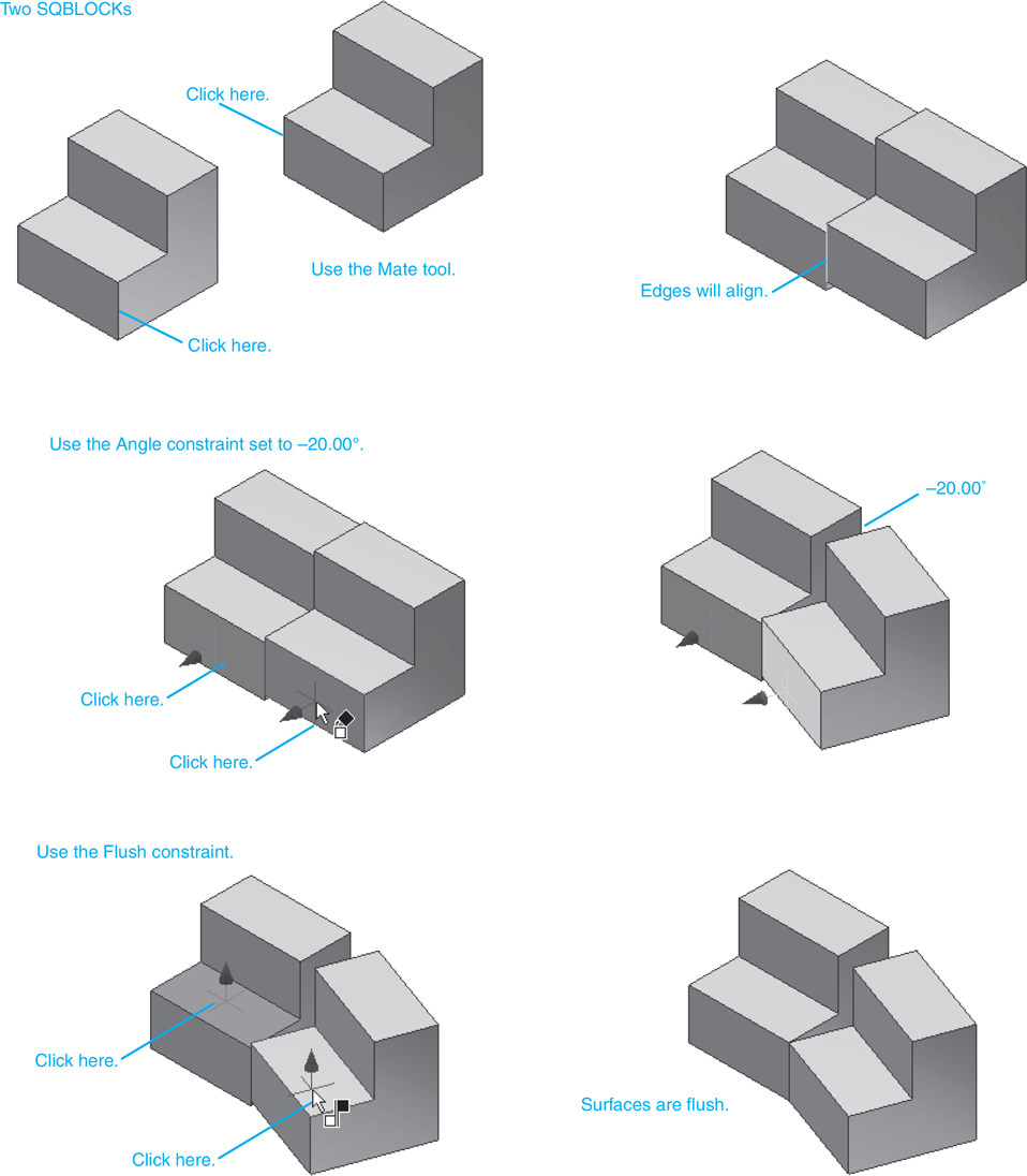
Figure 5-18
![]() Access the Angle constraint, set the angle for −20.00, and click the two front surfaces of the SQBLOCKs as shown.
Access the Angle constraint, set the angle for −20.00, and click the two front surfaces of the SQBLOCKs as shown.
![]() Click the Apply box.
Click the Apply box.
![]() Click the Flush constraint and align the two surfaces as shown.
Click the Flush constraint and align the two surfaces as shown.
Exercise 5-11 Using the Tangent Option
Figure 5-19 shows two cylinders. The smaller cylinder has dimensions of Ø10 × 20, and the larger cylinder has dimensions of Ø20 × 20 with a Ø10 centered longitudinal hole.

Figure 5-19
![]() Click the Constrain tool.
Click the Constrain tool.
The Place Constraint dialog box will appear. See Figure 5-20.

Figure 5-20
![]() Click the Tangent box under the Type heading.
Click the Tangent box under the Type heading.
The Outside option will be selected automatically.
![]() Select the outside edge of the large cylinder, then the outside edge of the smaller cylinder.
Select the outside edge of the large cylinder, then the outside edge of the smaller cylinder.
Figure 5-21 shows the resulting tangent constraint for the cylinders.

Figure 5-21
Exercise 5-12 Using the Insert Option
![]() Click the Constrain tool.
Click the Constrain tool.
The Place Constraint dialog box will appear. See Figure 5-22.

Figure 5-22
![]() Click the Insert box under the Type heading, then click the Aligned box under the Solution heading.
Click the Insert box under the Type heading, then click the Aligned box under the Solution heading.
Note that the Aligned box is the right-hand box.
![]() Click the top surface of each cylinder as shown.
Click the top surface of each cylinder as shown.
See Figure 5-23.

Figure 5-23
![]() Click the Apply button.
Click the Apply button.
Figure 5-23 also shows the result of using the Opposed option under the Solution heading.
Sample Assembly Problem SP5-1
Figure 5-24 shows three models that will be used to create an assembly drawing. The dimensions for the models are given in the figure.

Figure 5-24
![]() Create a new drawing using the Standard (mm).iam format.
Create a new drawing using the Standard (mm).iam format.
![]() Use the Place tool on the Component panel under the Assemble tab and place the Block, Bottom; Block, Top; and Post, Ø10 × 20 on the drawing screen.
Use the Place tool on the Component panel under the Assemble tab and place the Block, Bottom; Block, Top; and Post, Ø10 × 20 on the drawing screen.
This will be a bottom-up assembly.
![]() Click the Constrain tool and use the Mate option to align the two edges as shown.
Click the Constrain tool and use the Mate option to align the two edges as shown.
![]() Use the Flush constraint to align the front surfaces of the two blocks.
Use the Flush constraint to align the front surfaces of the two blocks.
![]() Use the Insert tool to locate the post in the holes in the blocks. See Figure 5-25.
Use the Insert tool to locate the post in the holes in the blocks. See Figure 5-25.

Figure 5-25
![]() Save the assembly.
Save the assembly.
Exercise 5-13 Saving an Assembly
![]() Create the assembly, then click the Save As heading under the I icon pull-down menu.
Create the assembly, then click the Save As heading under the I icon pull-down menu.
The file will be saved as an .iam file.
![]() Save the assembly using the file name BLOCK, ASSEMBLY; click Save.
Save the assembly using the file name BLOCK, ASSEMBLY; click Save.
Presentation Drawings
Presentation drawings are used to create exploded assembly drawings that can then be animated to show how the assembly is to be created from its components.
An exploded assembly drawing that can be animated to show how the assembly is to be created.
Exercise 5-14 Creating a Presentation Drawing
![]() Click on the New tool.
Click on the New tool.
The Create New File dialog box will appear. See Figure 5-26.

Figure 5-26
![]() Click the Standard (mm).ipn tool, then Create.
Click the Standard (mm).ipn tool, then Create.
The Presentation tab will appear. See Figure 5-27.

Figure 5-27
![]() Click the Insert Model tool on the Model panel under the Presentation tab.
Click the Insert Model tool on the Model panel under the Presentation tab.
The Insert dialog box will appear, listing all the existing assembly drawings. See Figure 5-28.

Figure 5-28
![]() Select the appropriate assembly drawing, then click Open.
Select the appropriate assembly drawing, then click Open.

Figure 5-29
The assembly will appear. See Figure 5-29.
Exercise 5-15 Creating an Exploded Assembly Drawing
![]() Click the Tweak Components tool located on the Component panel under the Presentation tab.
Click the Tweak Components tool located on the Component panel under the Presentation tab.
The Tweak Component tools will appear. See Figure 5-30.

Figure 5-30
![]() Select the post (the post will change to the color blue outline when selected).
Select the post (the post will change to the color blue outline when selected).
See Figures 5-31 and 5-32. An axis system will appear. Click, hold, and drag the Z-direction arrow (the arrow will be colored gold when selected). Right-click the mouse and select OK when a final post position is selected. See Figure 5-33.

Figure 5-31

Figure 5-32

Figure 5-33
![]() Select the top block and drag it to a position above the bottom block.
Select the top block and drag it to a position above the bottom block.
See Figure 5-34.

Figure 5-34
![]() Right-click the mouse and select OK.
Right-click the mouse and select OK.
Exercise 5-16 Saving the Presentation Drawing
![]() Click the Save As heading on the File pull-down menu under the I icon.
Click the Save As heading on the File pull-down menu under the I icon.
The Save As dialog box will appear.
![]() Enter the file name and click the Save box.
Enter the file name and click the Save box.
The drawing will be saved as an .ipn drawing. In this example the assembly drawing file named BLOCK, ASSEMBLY was used. The same name can be used because the file is saved using a different extension. In this example, the presentation drawing was labeled BLOCK, ASSEMBLY (2).
Exercise 5-17 Hiding a Trail
![]() Right-click the trail.
Right-click the trail.
![]() Select the Hide Trail Segment, Current option.
Select the Hide Trail Segment, Current option.
Tip
Note that if you delete a trail rather than using the Visibility option, the tweaking also will be deleted, and the models will return to their original assembled positions.
Animation
Presentation drawings can be animated using the Animate tool.
Exercise 5-18 Animating a Presentation Drawing
![]() Click on the Capture Camera tool on the Camera panel under the Presentation tab.
Click on the Capture Camera tool on the Camera panel under the Presentation tab.
The Animation dialog ribbon will appear. See Figure 5-35. The control buttons on the Animation dialog box are similar to those found on CD players.

Figure 5-35
![]() Click the Play forward button.
Click the Play forward button.
The assembly will be reassembled to original assembly drawing format, then exploded in the sequence used to define the tweaks.
![]() Save the exploded presentation drawing. The file name BLOCK, ASSEMBLY was used as this drawing has no trail lines.
Save the exploded presentation drawing. The file name BLOCK, ASSEMBLY was used as this drawing has no trail lines.
Isometric Drawings
Isometric drawings can be created directly from presentation drawings. Assembly numbers (balloons) can be added to the isometric drawings, and a parts list will automatically be created.
Exercise 5-19 Creating an Isometric Drawing
![]() Click on the New tool, then the Metric tab.
Click on the New tool, then the Metric tab.
The Create New File dialog box will appear. See Figure 5-36.

Figure 5-36
![]() Select the ANSI (mm).idw tool, and click Create.
Select the ANSI (mm).idw tool, and click Create.
The Place Views tools will appear in the tab. See Chapter 4 for a further explanation of the Place Views tools.
![]() Click the Base View tool.
Click the Base View tool.
The Drawing View dialog box will appear. See Figure 5-36.
![]() Click the Open an existing file button.
Click the Open an existing file button.
The Open dialog box will appear. See Figure 5-37.

Figure 5-37
Tip
Set the Files of type box for Inventor Files (*.ipt, *.iam, *.ipn) to assure that all files are available.
Ensure that all files are listed.
![]() Select the appropriate presentation drawing (file type is .ipn), then click Open.
Select the appropriate presentation drawing (file type is .ipn), then click Open.
The Drawing View dialog box will reappear. See Figure 5-38.

Figure 5-38
![]() Click OK (if needed).
Click OK (if needed).
![]() Click the Projected tool on the Create panel under the Place Views tab. Click the top view of the assembly and move the cursor up and to the right.
Click the Projected tool on the Create panel under the Place Views tab. Click the top view of the assembly and move the cursor up and to the right.
An exploded isometric view will appear.
![]() Left click a location for the Isometric view, right-click the mouse, and select the Create option. Delete the initial top view.
Left click a location for the Isometric view, right-click the mouse, and select the Create option. Delete the initial top view.
Figure 5-39 shows the resulting isometric view. Figure 5-40 shows the isometric drawing created using the Shaded option.

Figure 5-39

Figure 5-40
Assembly Numbers
Assembly numbers are added to an isometric drawing using the Balloon tool.
Exercise 5-20 Adding Balloons
![]() While still working on the ANSI (mm).idw template, click the Annotation tab, then click the Balloon option. Click the BLOCK, BOTTOM component.
While still working on the ANSI (mm).idw template, click the Annotation tab, then click the Balloon option. Click the BLOCK, BOTTOM component.
See Figures 5-41 and 5-42.

Figure 5-41

Figure 5-42
The BOM Properties dialog box will appear. See Figure 5-42.
![]() Click the topmost edge line of the BLOCK, BOTTOM.
Click the topmost edge line of the BLOCK, BOTTOM.
![]() Click OK, then drag the cursor away from the selected edge line.
Click OK, then drag the cursor away from the selected edge line.
![]() Locate a position away from the component and click the left mouse button. Move the cursor in a horizontal direction and click the left mouse button again.
Locate a position away from the component and click the left mouse button. Move the cursor in a horizontal direction and click the left mouse button again.
![]() Right-click the mouse and select the Continue option.
Right-click the mouse and select the Continue option.
![]() Add balloons to the other components.
Add balloons to the other components.
![]() Press the <Esc> key after all balloon numbers have been assigned.
Press the <Esc> key after all balloon numbers have been assigned.
Note
Balloon numbers (assembly numbers) are also referred to as bubble numbers and are used to identify parts within an assembly. Assembly numbers are different from part numbers.
See Figure 5-43. The balloon numbers will be in the order the parts were added to the drawing.

Figure 5-43
Tip
Making the balloon leaders lines the same angle will give the drawing a well-organized appearance.
Exercise 5-21 Editing Balloons
In general, the biggest parts have the lowest numbers. The assigned numbers can be edited.
![]() Right-click the balloon to be edited and select the Edit Balloon option. See Figure 5-44. The Edit Balloon dialog box will appear. See Figure 5-45.
Right-click the balloon to be edited and select the Edit Balloon option. See Figure 5-44. The Edit Balloon dialog box will appear. See Figure 5-45.

Figure 5-44

Figure 5-45
![]() Make any needed changes in the Edit Balloon dialog box and click OK.
Make any needed changes in the Edit Balloon dialog box and click OK.
TIP
The terms parts list and BOM are interchangeable.
Parts List
A parts list can be created from an isometric drawing after the balloons have been assigned using the Parts List tool located on the Table panel under the Annotate tab.
Exercise 5-22 Creating a Parts List
![]() Click the Parts List tool on the Table panel.
Click the Parts List tool on the Table panel.
The Parts List dialog box will appear. See Figure 5-46.

Figure 5-46
![]() Move the cursor into the area around the isometric drawing.
Move the cursor into the area around the isometric drawing.
A broken red line will appear when the cursor is in the area.
![]() Click the left mouse button, then click the OK button on the Parts List dialog box. Move the cursor away from the isometric drawing area.
Click the left mouse button, then click the OK button on the Parts List dialog box. Move the cursor away from the isometric drawing area.
An outline of the parts list will appear and move with the cursor.
![]() Select a location for the parts list and left-click the mouse.
Select a location for the parts list and left-click the mouse.
Figure 5-47 shows the resulting drawing. The parts list was generated using information from the original model drawings and the presentation drawings. Your part numbers may be different. They will be the file names you assigned the part drawings.

Figure 5-47
Exercise 5-23 Editing a Parts List
![]() Move the cursor onto the parts list and right-click the mouse. The lettering in the parts list will turn red when activated.
Move the cursor onto the parts list and right-click the mouse. The lettering in the parts list will turn red when activated.
![]() Click the Edit Parts List option.
Click the Edit Parts List option.
The Parts List: BLOCK, ASSEMBLY (2).iam box will appear. See Figure 5-48. Click on a cell and either delete or add text. Figure 5-49 shows an edited parts list.

Figure 5-48

Figure 5-49
Inventor will automatically insert the file name of a component into the PART NUMBER column. In this example, the file names were removed, and part numbers and descriptions were added. See Figure 5-48. To add or delete information from a parts list, click the appropriate box, delete existing text, and type in the new text.
Naming and Adding New Columns
Each company or organization has its own system for naming parts. In the examples in this book, the noun, modifier format was used.
Exercise 5-24 Adding a New Column
Say two additional columns were required for the parts list shown in Figure 5-49: Material and Notes.
![]() Move the cursor onto the parts list area and right-click the mouse.
Move the cursor onto the parts list area and right-click the mouse.
![]() Select the Edit Parts List option.
Select the Edit Parts List option.
The Parts List dialog box will appear.
![]() Select Column Chooser.
Select Column Chooser.
The Parts List Column Chooser dialog box will appear. See Figure 5-50.

Figure 5-50
![]() Scroll down the Available Properties listing to see if the new column headings are listed.
Scroll down the Available Properties listing to see if the new column headings are listed.
![]() MATERIAL is listed, so click on the listing, then click the Add box in the middle of the screen.
MATERIAL is listed, so click on the listing, then click the Add box in the middle of the screen.
The heading MATERIAL will appear in the Selected Properties area. Use the Move Down and Move Up boxes to sequence the column headings.
The heading NOTES is not listed, so it must be defined.
![]() Click on the New Property box.
Click on the New Property box.
The Define New Property dialog box will appear. See Figure 5-51.

Figure 5-51
![]() Type in the name of the new column, then click OK.
Type in the name of the new column, then click OK.
In this example, a NOTES column was added.
Note that only uppercase letters are used to define column headings.
![]() Click the Add-> Option and arrange the Selected Properties in the desired sequence, and click OK.
Click the Add-> Option and arrange the Selected Properties in the desired sequence, and click OK.
The Parts List dialog box will reappear.
![]() Click Save, then click Done.
Click Save, then click Done.
![]() Delete the old parts list and enter a new one. The new parts list will include the edits.
Delete the old parts list and enter a new one. The new parts list will include the edits.
Figure 5-52 shows the revised column in the parts list. If no material is defined, the word Generic will appear. The material for a model will be assigned to the model drawing and brought forward into the parts list. The MATERIAL column can be edited like the other columns.

Figure 5-52
Figure 5-53 shows the edited parts list on the drawing.

Figure 5-53
Title Block
All drawings include a title block, usually located in the lower right corner of the drawing sheet, as Figure 5-54 shows. Text may be added to a title block under existing headings, or new headings may be added.

Figure 5-54
Exercise 5-25 Adding Text to a Title Block
![]() Right-click the drawing name (BLOCK, ASSEMBLY) in the Model browser box, then click the Properties option.
Right-click the drawing name (BLOCK, ASSEMBLY) in the Model browser box, then click the Properties option.
See Figure 5-55. The drawing’s iProperties dialog box will appear. Text can be typed into the iProperties dialog box and will appear on the title block. Figure 5-56 shows the Summary input.

Figure 5-55

Figure 5-56
![]() Click the Summary tab on the iProperties dialog box and enter the appropriate information.
Click the Summary tab on the iProperties dialog box and enter the appropriate information.
In this example, the Title, Author, and Company were added.
![]() Click the Project tab and add the Part Number. See Figure 5-57. In this example, the number AM312 was added. This is an assembly drawing number. Each individual part has its own number.
Click the Project tab and add the Part Number. See Figure 5-57. In this example, the number AM312 was added. This is an assembly drawing number. Each individual part has its own number.

Figure 5-57
![]() Click Apply and OK.
Click Apply and OK.
See Figure 5-57. Figure 5-58 shows the completed title block.

Figure 5-58
The title block included with Inventor is only one possible format. Each company and organization will have its own specifications.
Subassemblies
Figure 5-59 shows a slightly more complicated assembly than the BLOCK assembly used in the previous sections. It is called a PIVOT assembly. Figure 5-60 shows the components needed to create the assembly. This will be a bottom-up assembly. The dimensions for the parts are found in Project 5-14.

Figure 5-59

Figure 5-60
It is sometimes difficult to control the assembly constraints. The parts seem to move randomly about the screen when constraints are added. Figure 5-61 shows an example of an incorrect application of an assembly constraint. If this occurs, undo the incorrect application and consider temporarily fixing some constraints. The constraints can be deleted when no longer needed. The assembly sequence presented here is one of many different ones that could be used.

Figure 5-61
The PIVOT is grounded because it was the first component entered on the screen.
![]() Right-click HANDLE in the browser box and ground the handle.
Right-click HANDLE in the browser box and ground the handle.
More than one component may be grounded at one time. See Figure 5-62.

Figure 5-62
![]() Use the Insert constraint and insert the POST,LARGE into the top hole of the HANDLE.
Use the Insert constraint and insert the POST,LARGE into the top hole of the HANDLE.
Use the Offset option to center the post.
![]() Use Insert and position the POST,SMALL into the HANDLE.
Use Insert and position the POST,SMALL into the HANDLE.
See Figure 5-63.

Figure 5-63
![]() Use Insert and position the LINK onto the POST,SMALL.
Use Insert and position the LINK onto the POST,SMALL.
See Figure 5-64.

Figure 5-64
![]() Unground the HANDLE.
Unground the HANDLE.
![]() Save the assembly drawing as PIVOT ASSEMBLY.
Save the assembly drawing as PIVOT ASSEMBLY.
![]() Use Insert to position the subassembly into the PIVOT.
Use Insert to position the subassembly into the PIVOT.
See Figure 5-65.

Figure 5-65
![]() Use the Angle constraint to position the HANDLE relative to the LINK.
Use the Angle constraint to position the HANDLE relative to the LINK.
In this example, an angle of 100° was used. See Figure 5-66.

Figure 5-66
![]() Use Insert to position the BALL on top of the HANDLE.
Use Insert to position the BALL on top of the HANDLE.
See Figure 5-59.
Figure 5-67 shows a presentation drawing of the PIVOT ASSEMBLY, and Figure 5-68 shows an exploded isometric drawing of the assembly and a parts list.

Figure 5-67

Figure 5-68
Drawing Sheets
Some assemblies are so large they require larger paper sheet sizes. Drawings are prepared on predefined standard-size sheets of paper. Each standard size has been assigned a letter value. Figure 5-69 shows the letter values and the sheet size assigned to each. All these sizes and more are available within Inventor.

Figure 5-69
Figure 5-70 shows a drawing done on a C-size drawing sheet. Note the letter C in the title block. The drawing is crowded on the sheet, so a larger sheet size is needed.

Figure 5-70
Exercise 5-26 Changing a Sheet Size
![]() Locate the cursor on the Sheet:1 heading in the browser box and right-click the mouse.
Locate the cursor on the Sheet:1 heading in the browser box and right-click the mouse.
![]() Select the Edit Sheet option.
Select the Edit Sheet option.
The Edit Sheet dialog box will appear. See Figure 5-71.

Figure 5-71
![]() Select the D option and click OK.
Select the D option and click OK.
See Figure 5-72. Note that the letter C has been replaced with the letter D, and the sheet size has changed.

Figure 5-72
Exercise 5-27 Adding More Sheets to a Drawing
Sometimes assembly drawings are so large they require more than one sheet.
![]() Click the New Sheet tool located on the Sheets panel under the Place Views tab.
Click the New Sheet tool located on the Sheets panel under the Place Views tab.
![]() A Sheet:2 listing will appear in the browser box. See Figure 5-73.
A Sheet:2 listing will appear in the browser box. See Figure 5-73.
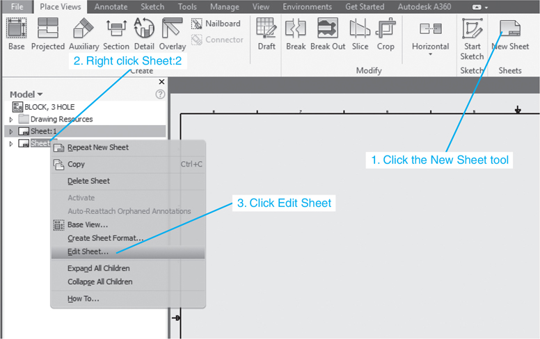
Figure 5-73
![]() Right-click the Sheet:2 callout and select the Edit Sheet option.
Right-click the Sheet:2 callout and select the Edit Sheet option.
![]() Select the desired sheet size and click OK.
Select the desired sheet size and click OK.
A new sheet will appear on the screen. See Figure 5-74.

Figure 5-74
Other Types of Drawing Blocks
Release Blocks
Figure 5-75 shows an enlarged view of the title block. The area on the left side of the block is called a release block. After a drawing is completed, it is first checked. If the drawing is acceptable, the checker will initial the drawing and forward it to the next approval person. Which person(s) and which department approve new drawings varies, but until a drawing is “signed off”—that is, all required signatures have been entered—it is not considered a finished drawing.
The area in a title block where required approval signatures are entered.
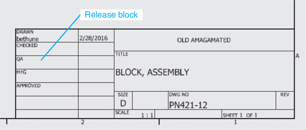
Figure 5-75
Revision Blocks
Figure 5-76 shows a sample revision block. It was created using the Revision Table tool located on the Table panel under the Annotate tab. Drawings used in industry are constantly being changed. Products are improved or corrected, and drawings must reflect and document these changes.
The area in a drawing where changes are listed by number with a brief description of the change.

Figure 5-76
Drawing changes are listed in the revision block by number. Revision blocks are usually located in the upper right corner of the drawing.
Exercise 5-28 Creating a Revision Block
![]() Click the Revision Table tool on the Table panel.
Click the Revision Table tool on the Table panel.
The Revision Table dialog box will appear on the screen. See Figure 5-77. Revisions are usually numbered starting with 1. The default Start Value shown in the Revision Table dialog box is 1. The numbers shown in the revision tag should correspond to numbers listed under the REV heading in the revision block.

Figure 5-77
![]() Click OK.
Click OK.
An outline of the revision block will appear on the screen. Revision blocks are usually located in the upper right corner of the drawing. Move the rectangular outline to the upper right corner of the drawing and click the mouse.
Each drawing revision is listed by number in the revision block. A brief description of the change is also included. It is important that the description be as accurate and complete as possible. The zone on the drawing where the revision is located is also specified.
The revision number is added to the field of the drawing in the area where the change was made. The revision letter is located within a “flag” to distinguish it from dimensions and drawing notes. The flag is created using the Revision Tag tool located on the Table panel under the Annotate tab. See Figure 5-76. The Revision Tag tool is a flyout from the Revision Table tool.
To change the number within a revision tag, right-click the tag and select the Edit Revision Tag option. A text dialog box will appear, and the tag number may be changed. See Figure 5-78.

Figure 5-78
Exercise 5-29 Editing the Revision Block
![]() Move the cursor onto the revision block.
Move the cursor onto the revision block.
Filled green circles will appear around the revision block. See Figure 5-79.

Figure 5-79
![]() Right-click the mouse and select the Edit option.
Right-click the mouse and select the Edit option.
The Revision Table dialog box will appear. The block’s headings may be edited or rearranged as needed. See Figure 5-80.

Figure 5-80
ECOs
Most companies have systems in place that allow engineers and designers to make quick changes to drawings. These change orders are called engineering change orders (ECOs), engineering orders (EOs), or change orders (COs), depending on the company’s preference. Change orders are documented on special drawing sheets that are usually stapled to a print of the drawing. Figure 5-81 shows a sample change order attached to a drawing.

Figure 5-81
After a number of change orders have accumulated, they are incorporated into the drawing. This process is called a drawing revision, which is different from a revision to the drawing. Drawing revisions are usually identified by a letter located somewhere in the title block. The revision letters may be included as part of the drawing number or in a separate box in the title block. Whenever you are working on a drawing, make sure you have the latest revision and all appropriate change orders. Companies have recording and referencing systems for listing all drawing revisions and drawing changes.
A version of a drawing into which change orders have been incorporated.
Drawing Notes
Drawing notes are used to provide manufacturing information that is not visual; for example, finishing instructions, torque requirements for bolts, and shipping instructions.
Drawing notes are usually listed on the right side of the drawing above the title block. Drawing notes are listed by number. If a note applies to a specific part of the drawing, the note number is enclosed in a triangle. The note numbers enclosed in triangles are also drawn next to the corresponding areas of the drawing. See Figure 5-82.

Figure 5-82
Top-Down Assemblies
A top-down assembly is an assembly that creates new parts as the assembly is created. Figure 5-83 shows a ROTATOR ASSEMBLY that was created using the top-down method. This section will explain how the assembly was created.

Figure 5-83
Exercise 5-30 Starting an Assembly
When creating a top-down assembly, start by saving the assembly drawing. Individual components can then be added to the assembly drawing.
![]() Click on the New tool.
Click on the New tool.
![]() Click the Metric tab, and select Standard (mm).iam.
Click the Metric tab, and select Standard (mm).iam.
The Assemble tab will appear.
![]() Left-click on the heading Assembly1 in the browser box.
Left-click on the heading Assembly1 in the browser box.
See Figure 5-84.


Figure 5-84
![]() Click the File tab and select the Save As tool from the cascading menu.
Click the File tab and select the Save As tool from the cascading menu.
The Save As dialog box will appear. See Figure 5-84.
![]() Name the assembly, then click Save.
Name the assembly, then click Save.
In this example, the assembly was named ROTATOR ASSEMBLY.
Exercise 5-31 Changing the Sketch Plane
The parts created for this assembly were created on the XZ plane. This gives the assembly a more realistic orientation.
![]() Click the Tools tab at the top of the screen and select Application Options.
Click the Tools tab at the top of the screen and select Application Options.
![]() Click the Part tab.
Click the Part tab.
![]() Select the Sketch on x-z plane button, then Apply and Close.
Select the Sketch on x-z plane button, then Apply and Close.
See Figure 5-85.

Figure 5-85
Exercise 5-32 Creating a Part
![]() Click the Create Component tool on the Component panel under the Assemble tab.
Click the Create Component tool on the Component panel under the Assemble tab.
The Create In-Place Component dialog box will appear. See Figure 5-86.

Figure 5-86
![]() Change the file name to PLATE. Select a file location.
Change the file name to PLATE. Select a file location.
![]() Click the Browse Templates box located to the right of the Template box.
Click the Browse Templates box located to the right of the Template box.
The Open Template dialog box will appear.
![]() Click the Metric tab, then select the Standard (mm).ipt option, then OK.
Click the Metric tab, then select the Standard (mm).ipt option, then OK.
![]() The Create In-Place Component dialog box will appear. Click OK. Type in the New Component Name, PLATE, then click OK.
The Create In-Place Component dialog box will appear. Click OK. Type in the New Component Name, PLATE, then click OK.
A cursor will appear with a 3D box next to it.
![]() Left-click the mouse.
Left-click the mouse.
![]() Move the cursor into the ViewCube area and click the icon that looks like a house.
Move the cursor into the ViewCube area and click the icon that looks like a house.
This is the Home tool. An axis will appear on the screen.
![]() Click the Create 2D Sketch tool.
Click the Create 2D Sketch tool.
The Sketch panel will appear in the panel box area.
![]() Select a sketch plane.
Select a sketch plane.
![]() Use the Two Point Rectangle, Line, and Dimension tools to create the PLATE shown in Figure 5-87.
Use the Two Point Rectangle, Line, and Dimension tools to create the PLATE shown in Figure 5-87.

Figure 5-87
The line labeled “Central line” is not an edge. It is a single line that will be used to help assemble the parts.
Exercise 5-33 Adding Work Points and a Work Axis
![]() Right-click the mouse and select the Finish 2D Sketch option, and click the 3DModel tab.
Right-click the mouse and select the Finish 2D Sketch option, and click the 3DModel tab.
The 3D Model panel will appear.
Tip
Do not select the Finish Edit option.
![]() Click the Work Point option located on the Work Features pane under the 3D Model tab, and locate work points at both ends of the central line.
Click the Work Point option located on the Work Features pane under the 3D Model tab, and locate work points at both ends of the central line.
![]() Click the Work Axis tool and add a work axis between the two work points.
Click the Work Axis tool and add a work axis between the two work points.
The new work axis will be through the points and parallel to the baseline of the plate. The work points and work axis will be listed in the browser area.
![]() Click on Origin under PLATE in the browser area.
Click on Origin under PLATE in the browser area.
![]() Click the XY Plane under Plate:1 and add a work axis through both work points.
Click the XY Plane under Plate:1 and add a work axis through both work points.
The planes used to create this assembly are unique to this example. Other combinations of planes can be used.
![]() Right-click the mouse and select the Finish Edit option.
Right-click the mouse and select the Finish Edit option.
See Figure 5-88.

Figure 5-88
![]() Save the drawing.
Save the drawing.
Tip
The work axis perpendicular to the XZ plane must appear on both sides of the PLATE.
Each of the four parts that make up the assembly must be created as individual drawings. Be sure to use the Create Component tool for each part. Each part should be listed in the browser box.
Exercise 5-34 Creating LINK-L
![]() Click the Assemble tab in the browser box, click on the Create Component tool, and create a new component named LINK-L.
Click the Assemble tab in the browser box, click on the Create Component tool, and create a new component named LINK-L.
The Create In-Place Component dialog box will appear. See Figure 5-86. Click the Browse Templates box, and click the Metric tab in the Open Template dialog box that will appear. Create the LINK-L component using the Standard (mm).ipt format. Define the new component’s file name. In this example the name LINK-L was assigned.
![]() Click the drawing screen, click the Create 2D Sketch tool, select the appropriate plane, and use the Circle, Line, and Dimension tools on the Sketch panel to create LINK-L as shown in Figure 5-89.
Click the drawing screen, click the Create 2D Sketch tool, select the appropriate plane, and use the Circle, Line, and Dimension tools on the Sketch panel to create LINK-L as shown in Figure 5-89.

Figure 5-89
![]() Right-click the mouse and select the Finish 2D Sketch option.
Right-click the mouse and select the Finish 2D Sketch option.
![]() Click the 3D Model tab, and use the Work Point tool to create work points at the center points of both circles. Use the Work Axis tool to create a work axis between the two holes’ centers.
Click the 3D Model tab, and use the Work Point tool to create work points at the center points of both circles. Use the Work Axis tool to create a work axis between the two holes’ centers.
![]() Use the Work Axis tool and the XZ Plane option listed under Origin under LINK-L in the browser area to create two work axes through the two work points, perpendicular to the XZ plane.
Use the Work Axis tool and the XZ Plane option listed under Origin under LINK-L in the browser area to create two work axes through the two work points, perpendicular to the XZ plane.
See Figure 5-90.

Figure 5-90
![]() Right-click the mouse and select Finish Edit.
Right-click the mouse and select Finish Edit.
Exercise 5-35 Copying a Component
Figure 5-91 shows the drawing screen with the PLATE and LINK-L components. The LINK-L component will be copied and the copy’s name changed to LINK-R.

Figure 5-91
![]() Right-click the LINK-L:1:1 in the browser box. See Figure 5-92.
Right-click the LINK-L:1:1 in the browser box. See Figure 5-92.


Figure 5-92
A dialog box will appear.
![]() Click the Copy option.
Click the Copy option.
![]() Move the cursor next to Link-L, right-click the mouse, and select the Paste option.
Move the cursor next to Link-L, right-click the mouse, and select the Paste option.
A copy of the LINK-L will appear on the screen. LINK-L will be renamed LINK-L:1 and the copied link will be named LINK-L:2. The new names will appear in the browser box.
![]() Click the LINK-L:2 heading in the browser box and change the name to LINK-R. See Figure 5-93.
Click the LINK-L:2 heading in the browser box and change the name to LINK-R. See Figure 5-93.

Figure 5-93
Check to see that the work points and axis created for LINK-L have been copied onto LINK-R in the browser box. See Figure 5-94.

Figure 5-94
Exercise 5-36 Creating the CROSSLINK
![]() Double-click the assembly name in the browser box, and use the Create Component tool to create the CROSSLINK using the dimensions presented in Figure 5-95.
Double-click the assembly name in the browser box, and use the Create Component tool to create the CROSSLINK using the dimensions presented in Figure 5-95.

Figure 5-95
Click the Create Component tool. See Figure 5-86. Click the Browse Templates box, and click the Metric tab in the Open Template dialog box that will appear. Create the new component using the Standard (mm).ipt format. Define the new component’s file name as CROSSLINK.
Note
All four components that make up the assembly should now be listed in the browser box.
![]() Click OK and move the cursor into the drawing area and click the left mouse button.
Click OK and move the cursor into the drawing area and click the left mouse button.
![]() Use the Create 2D Sketch tool and draw the CROSSLINK using the dimensions shown in Figures 5-95 and 5-96.
Use the Create 2D Sketch tool and draw the CROSSLINK using the dimensions shown in Figures 5-95 and 5-96.

Figure 5-96
![]() Right-click the mouse and select the Finish 2D Sketch option.
Right-click the mouse and select the Finish 2D Sketch option.
![]() Select the appropriate orientation.
Select the appropriate orientation.
![]() Add work points and axes as shown.
Add work points and axes as shown.
Note
The work axis should appear equal on both sides of the work point. If it appears on only one side, undo and redefine the sketch.
![]() Right-click the mouse and select the Finish Edit option.
Right-click the mouse and select the Finish Edit option.
The browser box should look like the one shown in Figure 5-96.
Exercise 5-37 Assembling the Parts
![]() Return to the Assemble tab.
Return to the Assemble tab.
![]() Click the Constrain tool.
Click the Constrain tool.
The Place Constraint dialog box will appear.
![]() Select the Mate option.
Select the Mate option.
![]() Select the work axes as shown in Figure 5-97.
Select the work axes as shown in Figure 5-97.

Figure 5-97
![]() Click Apply.
Click Apply.
![]() Assure that the Mate tool is still active and mate the work axes as shown in Figure 5-98.
Assure that the Mate tool is still active and mate the work axes as shown in Figure 5-98.

Figure 5-98
![]() Assure that the Mate tool is still active and mate the work axes shown in Figures 5-99 and 5-100.
Assure that the Mate tool is still active and mate the work axes shown in Figures 5-99 and 5-100.

Figure 5-99

Figure 5-100
Tip
Select the work axes that are perpendicular to the XZ plane. Do not select the work points. Make the selections on the perpendicular work axis away from the work points.
Figure 5-101 shows the resulting assembly drawing.

Figure 5-101
Exercise 5-38 Animating the LINKs
![]() Access the Assemble tab.
Access the Assemble tab.
![]() Right-click the PLATE heading in the browser box and create a work axis on the edge of the PLATE, as shown in Figure 5-101.
Right-click the PLATE heading in the browser box and create a work axis on the edge of the PLATE, as shown in Figure 5-101.
![]() Right-click the mouse and click the Finish Edit box. Click the Constrain tool.
Right-click the mouse and click the Finish Edit box. Click the Constrain tool.
The Place Constraint dialog box will appear.
![]() Select the Angle option.
Select the Angle option.
The default angle setting is 0.00 deg.
![]() Click the vertical work axis on the PLATE created in step 2, click the vertical axis of LINK-L:2, and click the vertical work axis on the PLATE again. See Figure 5-102.
Click the vertical work axis on the PLATE created in step 2, click the vertical axis of LINK-L:2, and click the vertical work axis on the PLATE again. See Figure 5-102.

Figure 5-102
The Apply option will be activated when the selections have been made.
NOTE: Click the axis line located on the edge of the PLATE above the edge’s centerline.
![]() Click Apply.
Click Apply.
Exercise 5-39 Setting the Assembly in Motion
![]() Right-click the Angle:1 (0.00 deg) constraint in the browser area, and select the Drive option.
Right-click the Angle:1 (0.00 deg) constraint in the browser area, and select the Drive option.
See Figure 5-103. The Drive Constraint dialog box will appear. See Figure 5-104.

Figure 5-103

Figure 5-104
![]() Set the End angle for 720.00 deg.
Set the End angle for 720.00 deg.
![]() Click the Forward button.
Click the Forward button.
The assembly should rotate freely. If the rotation is not correct, check the constraints.
Exercise 5-40 Controlling the Speed of the Rotation
![]() Click the >> button in the lower right corner of the Drive Constraint dialog box.
Click the >> button in the lower right corner of the Drive Constraint dialog box.
The box will expand. See Figure 5-105.

Figure 5-105
![]() Set the Increment value to 5.00 deg.
Set the Increment value to 5.00 deg.
![]() Click the Forward button.
Click the Forward button.
The higher the Increment value, the faster the assembly will rotate. The Repetitions setting is used to control the number of revolutions generated.
Exercise 5-41 Completing the PLATE
So far, only outlines of the components have been created. This is a good way to check the motion. Now we will complete the components, turning them into solid models.
![]() Right-click the heading PLATE in the browser box.
Right-click the heading PLATE in the browser box.
![]() Select the Open option, and click the Home icon to create an isometric view.
Select the Open option, and click the Home icon to create an isometric view.
![]() Select the Extrude tool and set the Extents Distance to 15 mm.
Select the Extrude tool and set the Extents Distance to 15 mm.
See Figure 5-106.

Figure 5-106
![]() Click OK.
Click OK.
![]() Click the Hole tool. Use the two existing work points as center points for two Ø10.0 holes.
Click the Hole tool. Use the two existing work points as center points for two Ø10.0 holes.
See Figure 5-107.

Figure 5-107
![]() Save the PLATE changes.
Save the PLATE changes.
![]() Click the X in the upper right corner to return to the assembly drawing. Save the drawing.
Click the X in the upper right corner to return to the assembly drawing. Save the drawing.
Exercise 5-42 Completing LINK-L and LINK-R
![]() Right-click LINK-L:1 in the browser area and select the Open option.
Right-click LINK-L:1 in the browser area and select the Open option.
![]() Right-click the word Sketch 1 under the LINK-L:1 heading and select the Edit Sketch option.
Right-click the word Sketch 1 under the LINK-L:1 heading and select the Edit Sketch option.
![]() Draw two tangent lines as shown in Figure 5-108.
Draw two tangent lines as shown in Figure 5-108.


Figure 5-108
![]() Click the Finish 2D Sketch tool and extrude LINK-L 5 mm.
Click the Finish 2D Sketch tool and extrude LINK-L 5 mm.
![]() Right-click the mouse and select the New Sketch option. Sketch a Ø10 circle. Right-click the mouse and click the Finish 2D Sketch option.
Right-click the mouse and select the New Sketch option. Sketch a Ø10 circle. Right-click the mouse and click the Finish 2D Sketch option.
![]() Extrude the top circle 11 forward.
Extrude the top circle 11 forward.
The 11 extrusions will create a 1 offset from the CROSSLINK.
![]() Reorient LINK-L:1 so that the back surface is visible, right-click the mouse, and select the New Sketch option.
Reorient LINK-L:1 so that the back surface is visible, right-click the mouse, and select the New Sketch option.
![]() Sketch a Ø10 circle, right-click the mouse, and select the Finish 2D Sketch option.
Sketch a Ø10 circle, right-click the mouse, and select the Finish 2D Sketch option.
![]() Extrude the circle a distance of 16.
Extrude the circle a distance of 16.
The 16 extrusion will create a 1 offset from the PLATE.
![]() Edit LINK-L:2 to the same dimensions and features.
Edit LINK-L:2 to the same dimensions and features.
![]() Save the LINKs.
Save the LINKs.
![]() Click the X in the upper right corner of the screen to return to the assembly drawing.
Click the X in the upper right corner of the screen to return to the assembly drawing.
Exercise 5-43 Completing the CROSSLINK
![]() Right-click CROSSLINK in the browser area and select the Open option.
Right-click CROSSLINK in the browser area and select the Open option.
![]() Add two tangent lines and extrude the CROSSLINK 10 mm.
Add two tangent lines and extrude the CROSSLINK 10 mm.
See Figure 5-109.

Figure 5-109
![]() Create two Ø10 holes as shown.
Create two Ø10 holes as shown.
![]() Save the CROSSLINK.
Save the CROSSLINK.
![]() Click the X in the upper right corner of the screen to return to the assembly drawing.
Click the X in the upper right corner of the screen to return to the assembly drawing.
Aligning the Assembly
Now that the components have thickness, they may not be aligned correctly; that is, they interfere with each other. The alignment could have been created as the components were constrained in the last section by defining offset values. Rotate the assembly and see if there is any interference or if the components are too far apart. See Figure 5-110. Use the Flush constraint and create a 1 offset between the parts if needed. The extrusion distances of 11 and 16 should help create the offset. Align the front surface of the CROSSLINK with the top of the Ø10 × 11 post on the LINKs and the back of the PLATE with the top of the Ø10 × 16 post. The finished assembly should look like Figure 5-111.

Figure 5-110

Figure 5-111
Presentations
Figure 5-112 shows a presentation drawing of the ROTATOR, and Figure 5-113 shows an exploded isometric drawing created using the .idw format.

Figure 5-112

Figure 5-113
Editing a Part within an Assembly Drawing
Figure 5-114 shows an assembly drawing called 114-ASSEMBLY. It is made from three components: 114-PLATE, 114-BRACKET, and 114-POST. The 114 PLATE is 40 × 90 with six evenly Ø10 holes, 10,10 from the corners. The 114 BRACKET is 30 × 30 × 40 with two Ø holes 10,10 from the corners. The 114 POST is Ø10 × 20. All thicknesses equal 10.

Figure 5-114
Exercise 5-44 Editing a Feature
It has been determined that the Ø10 mm holes in the bracket are too small. They are to be increased to Ø11 mm. The holes are features.
![]() Right-click the 114-BRACKET heading in the browser box.
Right-click the 114-BRACKET heading in the browser box.
See Figure 5-115. A list of options will appear. See Figure 5-116.

Figure 5-115

Figure 5-116
![]() Click the Open option.
Click the Open option.
![]() Right-click the Extrusion 2 heading and select the Edit Sketch option. See Figure 5-116.
Right-click the Extrusion 2 heading and select the Edit Sketch option. See Figure 5-116.
The Sketch drawing will appear. See Figure 5-117.

Figure 5-117
![]() Change the hole’s diameter value from 10 to 11 mm. Click Finish 2d Sketch.
Change the hole’s diameter value from 10 to 11 mm. Click Finish 2d Sketch.
Tip
The hole’s locational dimensions could also be edited at this time.
The bracket will appear on the screen. Click the Close button (the X in the upper right corner of the bracket’s screen). See Figure 5-118.

Figure 5-118
![]() Click the Yes box.
Click the Yes box.
The assembly will appear.
![]() Click the bracket.
Click the bracket.
Figure 5-119 shows the edited bracket. Note the gap between the diameter 10 posts and the edited diameter 11 holes.

Figure 5-119
Exercise 5-45 Editing a Sketch
It has been determined that the length of the plate is to be increased from 90 mm to 100 mm. This change is a change to the initial sketch.
![]() Right-click the 114-PLATE:1 heading in the browser box.
Right-click the 114-PLATE:1 heading in the browser box.
A list of options will appear. See Figure 5-120.

Figure 5-120
![]() Select the Open option.
Select the Open option.
The browser box will change.
![]() Right-click the Extrusion1 heading in the browser box, then click the Edit Sketch heading.
Right-click the Extrusion1 heading in the browser box, then click the Edit Sketch heading.
See Figure 5-121. The original rectangular sketch will appear. See Figure 5-122.

Figure 5-121

Figure 5-122
![]() Double-click the 90 dimension value and enter a new value of 100; click the checkmark on the Edit Dimension box. See Figure 5-123.
Double-click the 90 dimension value and enter a new value of 100; click the checkmark on the Edit Dimension box. See Figure 5-123.

Figure 5-123
![]() Right-click the mouse and select the Finish 2D Sketch option.
Right-click the mouse and select the Finish 2D Sketch option.
The plate will appear on the screen.
![]() Click the Close box in the upper right corner of the plate’s screen.
Click the Close box in the upper right corner of the plate’s screen.
A warning box will appear. See Figure 5-124.

Figure 5-124
![]() Click the Yes box.
Click the Yes box.
The assembly will appear on the screen. See Figure 5-125.

Figure 5-125
![]() Click the plate.
Click the plate.
Note the increase in the plate’s length.
Patterning Components
Figure 5-126 shows an assembly in which a post is inserted into a plate. Posts are to be inserted into all 16 holes in the plate. The plate is 80 × 80 × 10. There are 16 Ø10 holes located 10 from each edge and 20 apart. The post is Ø10 × 20.


Figure 5-126
Exercise 5-46 Creating a Pattern of Components
![]() Select the Pattern Component tool located on the Component panel under the Assemble tab.
Select the Pattern Component tool located on the Component panel under the Assemble tab.
The Pattern Component dialog box will appear. See Figure 5-126.
![]() Select the Post as the component.
Select the Post as the component.
![]() Select the Rectangular tab.
Select the Rectangular tab.
![]() Define the Column direction, the number of components, and the spacing between components.
Define the Column direction, the number of components, and the spacing between components.
In this example, the holes in the plate are 20 mm apart.
![]() Define the Row direction and spacing.
Define the Row direction and spacing.
![]() Click OK.
Click OK.
Mirroring Components
Components within an assembly may be mirrored and added to the assembly. See Figure 5-127.


Figure 5-127
Exercise 5-47 Mirroring an Assembly
![]() Click the Mirror Component tool located on the Component panel under the Assemble tab.
Click the Mirror Component tool located on the Component panel under the Assemble tab.
The Mirror Components: Status dialog box will appear.
![]() Click the components to be mirrored.
Click the components to be mirrored.
In this example, all the components were selected. A listing of the selected components will appear in the Mirror Components: Status dialog box.
![]() Click the Mirror Plane box.
Click the Mirror Plane box.
![]() Select the right front vertical plane as the mirror plane.
Select the right front vertical plane as the mirror plane.
![]() Click Next.
Click Next.
The Mirror Components: File Names dialog box will appear. This is a listing of all components that are mirrored and have been added to the assembly. The box may be edited as needed. In this example, no changes were made.
![]() Click OK.
Click OK.
Copying Components
Components already on an assembly may be copied and added to the assembly. See Figure 5-128. In this example, the bracket and posts will be copied.

Figure 5-128
Exercise 5-48 Copying a Component
![]() Click the Copy Component tool located on the Pattern panel under the Assembly tab.
Click the Copy Component tool located on the Pattern panel under the Assembly tab.
The Copy tool is a flyout on the Pattern panel. The Copy Components: Status dialog box will appear.
![]() Select the bracket and two posts.
Select the bracket and two posts.
![]() Select OK.
Select OK.
The Copy Components: File Names dialog box will appear. This is a listing of all components that have been copied and added to the assembly.
![]() Move the copied component away from the assembly.
Move the copied component away from the assembly.
![]() Use the Constrain tool to position the copied component into the assembly.
Use the Constrain tool to position the copied component into the assembly.
Chapter Summary
This chapter explained how to create assembly drawings from individual parts. The tools in the Assemble tab were introduced and used in a bottom-up approach to create the first assembly drawing from an existing model. The method for grounding components was demonstrated. The Move and Rotate tools as well as all the options of the Constrain tool were used to manipulate components of the drawing.
The tools in the Presentation tab were used to explode an assembly drawing to show how the assembly is created from its components. The presentation drawing was then animated. Assembly numbers were added and edited to isometric views of the presentation drawing.
The other elements of a presentation drawing—the parts list or bill of materials, the title block, release blocks, and revision blocks—were also demonstrated.
The top-down approach to creating an assembly drawing was also illustrated, and various techniques for editing assembly drawings were explained, including patterning, mirroring, and copying components.
Chapter Test Questions
Multiple Choice
Circle the correct answer.
1. Which of the following is not an assembly constraint tool?
a. Flush
b. Insert
c. Bisect
d. Angle
2. Which tool is used to locate a shaft into a hole?
a. Flush
b. Insert
c. Bisect
d. Angle
3. Why is the Tweak tool used in presentation drawings?
a. To pull components apart
b. To edit components
c. To rotate components
4. What is the function of the Column Chooser option of the Edit Parts List dialog box?
a. To change the size of the columns
b. To arrange the columns in numerical order
c. To add, subtract, and edit columns
5. What is a subassembly?
a. Another name for an assembly drawing
b. A group of parts assembled together and then inserted as a group into an assembly
c. An assembly that is located below other assemblies
6. What are the dimensions of a C-size drawing sheet?
a. 8.5 × 11
b. 11 × 17
c. 17 × 22
7. What is the purpose of drawing revisions?
a. To document recent changes to a drawing
b. To indicate future changes to a drawing
c. To specify the drawing’s tolerances
8. Why are drawing notes added to a drawing?
a. To explain the functions of the drawing’s parts
b. To list the comments of the drawing’s engineer
c. To define manufacturing information that cannot be shown visually
9. Which tool is used to animate an assembly drawing?
a. Drive Constraint
b. Increment Constraint
c. Repetition Constraint
10. Which tool may be used to change the dimensions of an individual part?
a. Change Drawing
b. Edit Component
c. Modify Entity
Matching
Write the number of the correct answer on the line.
Column A |
Column B |
|---|---|
a. A4 ______ |
1. 8.5″ × 11″ |
b. C ______ |
2. 11″ × 17″ |
c. A ______ |
3. 17″ × 22″ |
d. A1 ______ |
4. 22″ × 34″ |
e. A2 ______ |
5. 210 mm × 297 mm |
f. B ______ |
6. 297 mm × 420 mm |
g. A3 ______ |
7. 420 mm × 594 mm |
h. D ______ |
8. 594 mm × 841 mm |
True or False
Circle the correct answer.
1. True or False: A bottom-up assembly drawing is created from existing drawings.
2. True or False: A top-down assembly drawing is created from existing drawings.
3. True or False: A grounded component has no degrees of freedom.
4. True or False: A presentation drawing is used to pull assembled components apart.
5. True or False: A presentation drawing can be animated.
6. True or False: An isometric assembly drawing is created using the ANSI.idw format.
7. True or False: Assembly numbers are the same as part numbers.
8. True or False: Assembly numbers are added to an assembly drawing using the Balloon tool.
9. True or False: A BOM is the same as a parts list.
10. True or False: ECOs are used to make quick changes to an existing drawing.
Chapter Projects
Project 5-1
A dimensioned block is shown in Figure P5-1 . Redraw this block and save it as SQBLOCK. See page 222. Use the SQBLOCK to create assemblies as shown.

Figure P5-1A MILLIMETERS

Figure P5-1B

Figure P5-1C

Figure P5-1D

Figure P5-1E

Figure P5-1F

Figure P5-1G
Pages 292–295 show a group of parts. These parts are used to create the assemblies presented as problems in this section. Use the given descriptions, part numbers, and materials when creating BOMs for the assemblies.
Project 5-2
Redraw the following models and save them as Standard (mm).ipn files. All dimensions are in millimeters.

Figure P5-2A

Figure P5-2B

Figure P5-2C

Figure P5-2D

Figure P5-2E

Figure P5-2F

Figure P5-2G

Figure P5-2H
Project 5-3
Draw an exploded isometric assembly drawing of Assembly 1. Create a BOM.

Figure P5-3A MILLIMETERS
ASSEMBLY 1

Figure P5-3B
Project 5-4
Draw an exploded isometric assembly drawing of Assembly 2. Create a BOM.

Figure P5-4A MILLIMETERS
ASSEMBLY 2

Figure P5-4B
Project 5-5
Draw an exploded isometric assembly drawing of Assembly 3. Create a BOM.

Figure P5-5A MILLIMETERS
ASSEMBLY 3

Figure P5-5B
Project 5-6
Draw an exploded isometric assembly drawing of Assembly 4. Create a BOM.

Figure P5-6A MILLIMETERS
ASSEMBLY 4

Figure P5-6B
Project 5-7
Draw an exploded isometric assembly drawing of Assembly 5. Create a BOM.

Figure P5-7A MILLIMETERS
ASSEMBLY 5

Figure P5-7B
Project 5-8
Draw an exploded isometric assembly drawing of Assembly 6. Create a BOM.

Figure P5-8A
ASSEMBLY 6

Figure P5-8B
Project 5-9
Create an original assembly based on the parts shown on pages 292–295. Include a scene, an exploded isometric drawing with assembly numbers, and a BOM. Use at least 12 parts.
Project 5-10
Draw the ROTATOR ASSEMBLY shown. Include the following:
An assembly drawing.
An exploded presentation drawing.
An isometric drawing with assembly numbers.
A parts list.
An animated assembly drawing; the LINKs should rotate relative to the PLATE. The LINKs should carry the CROSSLINK. The CROSSLINK should remain parallel during the rotation.

Figure P5-10
Note
This assembly was used in the section on top-down assemblies. See page 260.
Project 5-11
Draw the FLY ASSEMBLY shown. Include the following:
An assembly drawing.
An exploded presentation drawing.
An isometric drawing with assembly numbers.
A parts list.
An animated assembly drawing; the FLYLINK should rotate around the SUPPORT base.

Figure P5-11
Project 5-12
Draw the ROCKER ASSEMBLY shown. Include the following:
An assembly drawing
An exploded presentation drawing
An isometric drawing with assembly numbers
A parts list
An animated assembly drawing

Figure P5-12
Project 5-13
Draw the LINK ASSEMBLY shown. Include the following:
An assembly drawing.
An exploded presentation drawing.
An isometric drawing with assembly numbers.
A parts list.
An animated assembly drawing; the HOLDER ARM should rotate between −30° and +30°.

Figure P5-13
Project 5-14
Draw the PIVOT ASSEMBLY shown using the dimensioned components given. Include the following:
A presentation drawing
A 3D exploded isometric drawing
A parts list
Tip
This assembly was used in the section on subassemblies. See page 249.

Figure P5-14A MILLIMETERS

Figure P5-14B

Figure P5-14C

Figure P5-14D

Figure P5-14E

Figure P5-14F

Figure P5-14G

Figure P5-15