
Chapter Eleven. Bearings
Chapter Objectives
Understand the different types of bearings: plain, ball, and thrust
Learn how to select bearings from the Content Center
Understand how tolerances are used with bearings
Learn how to use bearings in assemblies
Introduction
This chapter discusses three types of bearings: plain, ball, and thrust. See Figure 11-1. Plain bearings are hollow cylinders that may have flanges at one end. Plain bearings are made from nylon or Teflon for dry (no lubrication) applications, and impregnated bronze or other materials when lubrications are used.
A hollow cylinder that may have a flange at one end and may or may not be lubricated; also called a sleeve bearing or a bushing.

Figure 11-1
Plain bearings require less space than other types of bearings and are less expensive but have higher friction properties.
Ball bearings are made from two cylindrical rings separated by a row of balls. Shapes other than spheres may be used (rollers), and more than one row of balls may be included. Ball bearings usually take more space than plain bearings and are more expensive. They have better friction properties than plain bearings.
A bearing made from two cylindrical rings separated by a row of balls or rollers.
Thrust bearings are used to absorb loads along the axial direction (the length of the shaft). They are similar in size and cost to ball bearings.
A bearing used to absorb a load along the axial direction of a shaft.
Plain Bearings
Figure 11-2 shows a U-bracket that will be used to support a rotating shaft. Plain bearings will be inserted between the shaft and the U-bracket. The bearings will be obtained from the Content Center.

Figure 11-2
The shaft has a nominal diameter of 6.00 mm, and the shaft will be inserted into the bearing and the bearing into the U-bracket.
Nomenclature
Plain bearings are also called sleeve bearings or bushings. The terms are interchangeable.
Note
When drawing a shaft use the nominal dimensions.
Shaft Tolerances
For this example, it is assumed that the shaft will be purchased from a vendor. Tolerances for purchased shafts can be found in the manufacturer’s catalogs or from listings posted on the Web. The shaft selected for this example has a tolerance of +0.00/-0.02.
Figure 11-3 shows a Ø6.0000 shaft 50.00 long. Each end has a 0.50 × 45° chamfer. It was created using the Shaft tool under the Design tab. See Chapter 10. The orthographic views of the shaft include the shaft’s diametric tolerance.
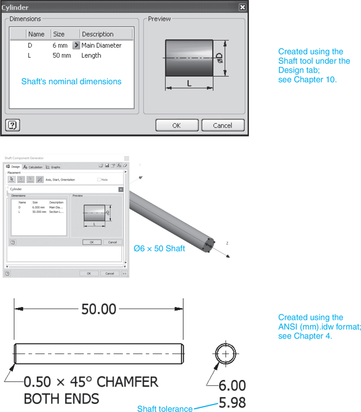
Figure 11-3
Tip
Purchased parts do not require individual drawings. They are listed in the parts list by manufacturer and manufacturer’s part number or catalog number.
Exercise 11-1 Selecting a Plain Bearing
![]() Draw the U-bracket shown in Figure 11-2 and save the drawing.
Draw the U-bracket shown in Figure 11-2 and save the drawing.
![]() Start a new drawing using the Standard (mm).iam format.
Start a new drawing using the Standard (mm).iam format.
![]() Use the Place Component tool and place the U-bracket on the drawing.
Use the Place Component tool and place the U-bracket on the drawing.
![]() Click the Place from Content Center tool or right-click the mouse and click the Place from Content Center option, click Shaft Parts, Bearings-Plain, and select an ISO 2795 (Cylindrical) plain bearing.
Click the Place from Content Center tool or right-click the mouse and click the Place from Content Center option, click Shaft Parts, Bearings-Plain, and select an ISO 2795 (Cylindrical) plain bearing.
See Figure 11-4.

Figure 11-4
![]() Select the 6× 10× 4 nominal-sized bearing.
Select the 6× 10× 4 nominal-sized bearing.
See Figure 11-5.
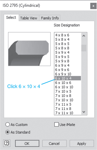
Figure 11-5
![]() Click OK and add two bearings to the drawing.
Click OK and add two bearings to the drawing.
See Figure 11-6.

Figure 11-6
Shaft/Bearing Interface
The shaft and inside diameter of the bearing (the bore) are generally fitted together using a clearance fit. The shaft has a tolerance of +0.00/−0.02. From manufacturer’s specifications we know that the bearing’s inside diameter is 6.00 nominal with a tolerance of +0.02/0.00. Therefore, the maximum clearance is 0.04, and the minimum is 0.00.
Note
If the clearance is too large, excessive vibrations could result at high speeds.
The range of clearance tolerance depends on the load and speed of the application.
The Hole in the U-Bracket
The bearing is to be inserted into the hole in the U-bracket using a force fit; that is, the outside diameter of the bearing will be larger than the diameter of the hole. Fits are often defined using a standard notation such as F7/h6, where the uppercase letter defines the hole tolerance and the lowercase letter defines the shaft tolerance. In this example, the outside diameter of the bearing uses the shaft values. See the tables in the Appendix. For a Ø10.00, the tolerances for an F7/h6 combination are
Hole: 9.991 |
Shaft: 10.000 |
Fit: 0.000 |
9.976 |
9.991 |
–0.024 |
This means that the hole in the U-bracket should be 9.991/9.976. However, a problem can arise if the manufacturer’s specifications for the outside diameter of the bearing do not match the stated h6 value of 10.000/9.991.
Say, for example, the given outside diameter for a bearing is 10.009/10.000. Although the tolerance range is the same, 0.009 (10.000 − 9.991 = 0.009), the absolute values are different. We use the fit values to determine the new hole values. The fit values are given as 0.000/−0.024. These values are the maximum and minimum interference. Applying these values to the hole, we get 10.000/9.985 (10.009 − 0.024=9.985). For this bearing, the hole in the U-bracket is 10.000/9.985.
Draw the hole using the nominal value of 10.00, and dimension the hole using the derived values. See Figure 11-7.

Figure 11-7
Figure 11-8 shows the finished assembly. The components were assembled using the Constrain tool. The shaft was offset 5 from the edge of the bearing.

Figure 11-8
Figure 11-9 shows the bearing assembly along with its parts list. Note that the bearing does not have an assigned part number, but uses the manufacturer’s number assigned by the Content Center. The U-bracket and the shaft both have assigned part numbers and would require detail drawings including dimensions and tolerances. Because the bearing is a purchased part, no drawing is required.

Figure 11-9
Figure 11-10 shows two plain bearings that include shoulders.

Figure 11-10
Ball Bearings
A bearing is to be selected for a Ø6.00 shaft. The shaft is to be mounted into the bearing and the bearing inserted into a U-bracket.
Exercise 11-2 Selecting a Ball Bearing
![]() Click the Place from Content Center tool and select Shaft, click Shaft Parts, Ball Bearings, Deep Groove Ball Bearings, and select a DIN 625 − T1 bearing.
Click the Place from Content Center tool and select Shaft, click Shaft Parts, Ball Bearings, Deep Groove Ball Bearings, and select a DIN 625 − T1 bearing.
See Figure 11-11. The DIN 625 − T1 dialog box shows that the bearings are defined by coded numbers.


Figure 11-11
![]() Click the Table View tab to see the dimensions for the different DIN 625 − T1 bearings.
Click the Table View tab to see the dimensions for the different DIN 625 − T1 bearings.
In this example, a 618/6 bearing was selected. This bearing has a nominal bore of Ø6.00 and an outside nominal diameter of 13.00. Assume the bearing has the tolerances shown in Figure 11-12.

Figure 11-12
![]() Calculate the shaft’s diameter.
Calculate the shaft’s diameter.
Say the clearance requirements for the shaft are
Clearance = minimum = 0.00
Clearance = maximum = 0.03
This means that the shaft diameter tolerances are 6.00/5.99.
![]() Use the Shaft tool under the Design tab to draw the shaft.
Use the Shaft tool under the Design tab to draw the shaft.
Use the nominal diameter of 6.00 and a length of 50. Add a 0.50 × 45° chamfer to each end. Figure 11-13 shows a solid model drawing of the shaft and a dimensioned orthographic drawing. The model was drawn using the nominal Ø6, and the orthographic views include the required tolerances.

Figure 11-13
![]() Determine the size for the hole in the U-bracket.
Determine the size for the hole in the U-bracket.
The interface between the outside diameter of the bearing and the U-bracket is defined as H7/s6. The values for this tolerance can be found in the tables in the Appendix or by using the Limits and Fits dialog boxes found in the Tolerance Calculator located on the Power Transmission panel under the Design tab.
![]() Access the Limits and Fits Mechanical Calculator.
Access the Limits and Fits Mechanical Calculator.
See Figure 11-14. The Limits and Fits Calculator is located by clicking the arrowhead next to the Power Transmission panel heading, clicking the arrowhead next to the Limits/Fits Calculator, and clicking the Limits/Fits Calculator option. Figure 11-14 shows the result for a clearance fit.

Figure 11-14
![]() Select the Hole-basis system of fits, enter a Basic Size of 13.00, and select an Interference fit.
Select the Hole-basis system of fits, enter a Basic Size of 13.00, and select an Interference fit.
See Figure 11-15. The tolerance values will appear under the Results heading. The hole’s values can also be obtained by moving the cursor to the H tolerance zone.

Figure 11-15
Tip
The terms Hole-basis and Shaft-basis refer to how the tolerance was calculated. In this example, note in the Results box that the minimum hole diameter is 13.000. This is the starting point for the tolerance calculations, so the calculation is hole-basis. If the minimum shaft diameter had been defined as 13.000, the tolerance calculations would have started from this value. The results would have been shaft-basis.
From Figure 11-15, we see that the hole has a tolerance of 13.027/13.000.
![]() Apply the hole tolerance to the hole in the U-bracket.
Apply the hole tolerance to the hole in the U-bracket.
See Figure 11-16.

Figure 11-16
Figure 11-17 shows the finished assembly drawing with the bearings. Figure 11-18 shows the parts list for the assembly. Note that no part number was assigned to the bearings, as they are purchased parts. The manufacturer’s part numbers were used.

Figure 11-17

Figure 11-18
Thrust Bearings
Tolerances for thrust bearings are similar to ball bearings. In general, a clearance fit is used between the shaft and the bearing’s bore (inside diameter), and an interference fit is used between the housing and the bearing’s outside diameter.
Exercise11-3 Selecting Thrust Bearings
![]() Create a drawing using the Standard (mm).iam format and access the Place from Content Center dialog box.
Create a drawing using the Standard (mm).iam format and access the Place from Content Center dialog box.
See Figure 11-19.

Figure 11-19
![]() Click on Thrust Ball Bearings and select an ANSI/AFBMA 24.1 TA - Thrust Ball Bearing.
Click on Thrust Ball Bearings and select an ANSI/AFBMA 24.1 TA - Thrust Ball Bearing.
The dialog box will appear showing the Size Designation using coded numbers. See Figure 11-20.

Figure 11-20
![]() Click the Table View tab to access the dimensions for the listed bearings.
Click the Table View tab to access the dimensions for the listed bearings.
![]() Select the 10TA12 Size Designation.
Select the 10TA12 Size Designation.
Figure 11-21 shows the bearing with dimensions and tolerances.

Figure 11-21
![]() Calculate the shaft’s diameter.
Calculate the shaft’s diameter.
Say the clearance requirements are
Clearance = minimum = 0.00
Clearance = maximum = 0.02
This means the shaft diameter tolerance is 10.00/9.99.
![]() Draw the shaft using the Shaft tool on the Design tab.
Draw the shaft using the Shaft tool on the Design tab.
Use the nominal diameter of 10.00 and a length of 30. Add a 0.50 × 45° chamfer to each end. Figure 11-22 shows a solid model drawing of the shaft and a dimensioned orthographic drawing. The model was drawn using the nominal Ø10, and the orthographic views include the required tolerances.

Figure 11-22
![]() Determine the size for the hole in the T-bracket.
Determine the size for the hole in the T-bracket.
The interface between the outside diameter of the bearing and the T-bracket is defined as H7/p6. The values for this tolerance can be found in the tables in the Appendix or by using the Limits and Fits dialog boxes found on the Power Transmission panel under the Design tab.
![]() Access the Limits/Fits Calculator tool.
Access the Limits/Fits Calculator tool.
See Figure 11-23.

Figure 11-23
![]() Select the Hole-basis system of fits, enter a Basic Size of 26.00, and select an Interference fit.
Select the Hole-basis system of fits, enter a Basic Size of 26.00, and select an Interference fit.
The tolerance values will appear under the Results heading. The hole’s values can also be obtained by moving the cursor to the H tolerance zone. The hole’s tolerance is Ø26.021/26.000.
In this example, the hole in the T-bracket will use a counterbored hole. The bearing has a thickness of 11.00, so the counterbored hole will have a depth of 11 and a diameter of 26.021/26.000.
![]() Apply the hole tolerances to the T-bracket.
Apply the hole tolerances to the T-bracket.
See Figure 11-24.

Figure 11-24
Chapter Summary
This chapter explained the differences among three types of bearings: plain, ball, and thrust. Various bearings were selected from the Content Center and used in drawings. The difference between shaft-basis and hole-basis tolerances was discussed and illustrated. Shafts and bearings were used in assemblies utilizing both clearance and force fits.
Chapter Test Questions
Multiple Choice
Circle the correct answer.
1. Which is a material that would not be used to make a sleeve bearing?
a. Teflon
b. Cast iron
c. Impregnated bronze
d. Nylon
2. In the notation H7/n6, the H7 specifies a standard tolerance for the
a. Hole
b. Shaft
c. Bearing diameter
d. Interference
3. In the notation H7/n6, the n6 specifies a standard tolerance for the
a. Hole
b. Shaft
c. Bearing diameter
d. Interference
4. Hole/shaft tolerance calculations that start with a hole’s diameter are called
a. First hole consideration
b. Datum hole calculations
c. Hole-basis
5. In general, what type of fit is the tolerance between a shaft and sleeve bushing?
a. Clearance
b. Interference
c. Transitional
Matching
Column A |
Column B |
|---|---|
a. Sleeve __________ |
1. A bearing that absorbs loads along an axial direction |
b. Ball __________ |
2. A bearing that looks like a hollow cylinder |
c. Thrust __________ |
3. A bearing that includes a row of spheres |
True or False
Circle the correct answer.
1. True or False: A sleeve bearing is also called a bushing.
2. True or False: A listing of bearings is found in the Content Center.
3. True or False: In general, ball bearings are less expensive than sleeve bearings.
4. True or False: Values for limit and fit tolerances are located under the Design tab.
5. True or False: The designation H7/h6 specifies a standard hole/shaft fit tolerance.
Chapter Projects
Figure P11-1 shows a Bearing Assembly drawing, a parts list, and detail drawings of all manufactured parts. Use the Bearing Assembly with Projects 11-1 through 11-8.


Figure P11-1

Figure P11-2
Project 11-1: Millimeters
Insert two Ø12 × 90 shafts with 0.50 × 45° chamfers at each end. Insert each shaft into a CNS 02 3481 A plain bearing. Insert the two bearing shaft subassemblies into the Bearing Assembly shown in Figure P11-1. See Figure P11-2 for the finished Bearing Assembly.
Assume the CNS 02 3481A plain bearing has an inside diameter of 12.01/12.00 and that the required clearance with the shaft is 0.00 minimum and 0.02 maximum. What is the diametric tolerance of the shafts? Create an orthographic drawing of one of the shafts with dimensions and tolerances.
Assume the CNS 02 3481 A plain bearing has an outside diameter of 16.039/16.028 and that the bearing will fit into the Side Part of the Bearing Assembly using an H7/s6 interference fit. What is the dimension and tolerance for the holes in the Side Part? Create an orthographic drawing of the Side Part and include all dimensions and tolerances.
Create a presentation drawing of the completed Bearing Assembly.
Create an exploded isometric drawing of the completed Bearing Assembly. Include assembly numbers and a parts list. The part number for the shaft is SH07-12.
Project 11-2: Millimeters
Insert two Ø16 × 90 shafts with 0.50 × 45° chamfers at each end. Insert each shaft into a CSN 9352 plain bearing. Insert the two bearing shaft subassemblies into the Bearing Assembly shown in Figure P11-1.
Assume the CSN 9352 A plain bearing has an inside diameter of 16.02/12.01 and that the required clearance with the shaft is 0.01 minimum and 0.04 maximum. What is the diametric tolerance of the shafts? Create an orthographic drawing of one of the shafts with dimensions and tolerances.
Assume the CSN 9352 A plain bearing has an outside diameter of 22.000/21.987 and that the bearing will fit into the Side Part of the Bearing Assembly using an S7/h6 interference fit (shaft basis). What is the dimension and tolerance for the holes in the Side Part? Create an orthographic drawing of the Side Part and include all dimensions and tolerances.
Create a presentation drawing of the completed Bearing Assembly.
Create an exploded isometric drawing of the completed Bearing Assembly. Include assembly numbers and a parts list. The part number for the shaft is SH07-16. See Figure P11-2.
Project 11-3: Millimeters
Insert two Ø10 × 130 shafts with 0.50 × 45° chamfers at each end. Insert each shaft into a DIN 1850-5 P plain bearing. Insert the two bearing shaft subassemblies into the Bearing Assembly shown in Figure P11-1.
Assume the DIN 1850-5 P plain bearing has an inside diameter of 10.02/12.00 and that the required clearance with the shaft is 0.00 minimum and 0.04 maximum. What is the diametric tolerance of the shafts? Create an orthographic drawing of one of the shafts with dimensions and tolerances.
Assume the DIN 1850-5 P plain bearing has an outside diameter of 16.000/15.989 and that the bearing will fit into the Side Part of the Bearing Assembly using an S7/h6 interference fit. What is the dimension and tolerance for the holes in the Side Part? Create an orthographic drawing of the Side Part and include all dimensions and tolerances.
Add CNS 122 collars to both ends of both shafts.
Create a presentation drawing of the completed Bearing Assembly.
Create an exploded isometric drawing of the completed Bearing Assembly. Include assembly numbers and a parts list. The part number for the shaft is SH08-16.
Project 11-4: Millimeters
Insert two Ø20 × 110 shafts with 1.00 × 45° chamfers at each end. Insert each shaft into a JIS B 1582 plain bearing. Insert the two bearing shaft subassemblies into the Bearing Assembly shown in Figure P11-1.
Assume the JIS B 1582 plain bearing has an inside diameter of 20.02/20.00 and that the required clearance with the shaft is 0.01 minimum and 0.05 maximum. What is the diametric tolerance of the shaft? Create an orthographic drawing of the shaft with dimensions and tolerances.
Assume the JIS B 1582 plain bearing has an outside diameter of 28.039/28.028 and that the bearing will fit into the Side Part of the Bearing Assembly using an H7/s6 interference fit. What is the dimension and tolerance for the holes in the Side Part? Create an orthographic drawing of the Side Part and include all dimensions and tolerances.
Add CNS 9074 retaining rings 5 mm from each end of both shafts.
Create a presentation drawing of the completed Bearing Assembly.
Create an exploded isometric drawing of the completed Bearing Assembly. Include assembly numbers and a parts list. The part number for the shaft is SH07-12.
Project 11-5: Millimeters
Insert two Ø10 × 90 shafts with 0.50 × 45° chamfers at each end. Insert each shaft into a BS 290–61800 ball bearing. Insert the two bearing shaft subassemblies into the Bearing Assembly shown in Figure P11-1.
Assume the BS 290–61800 ball bearing has an inside diameter of 10.02/10.00 and that the required clearance with the shaft is 0.00 minimum and 0.04 maximum. What is the diametric tolerance of the shafts? Create an orthographic drawing of one of the shafts with dimensions and tolerances.
Assume the BS 290–61800 ball bearing has an outside diameter of 16.000/15.989 and that the bearing will fit into the Side Part of the Bearing Assembly using a U7/h6 interference fit. What is the dimension and tolerance for the holes in the Side Part? Create an orthographic drawing of the Side Part and include all dimensions and tolerances.
Create a presentation drawing of the completed Bearing Assembly.
Create an exploded isometric drawing of the completed Bearing Assembly. Include assembly numbers and a parts list. The part number for the shaft is SH07-12.
Project 11-6: Millimeters
Insert two Ø15 × 130 Shafts with 0.50 × 45° chamfers at each end. Insert each shaft into a CSN 02 4630 2 61802 ball bearing. Insert the two bearing shaft subassemblies into the Bearing Assembly shown in Figure P11-1.
Assume the CSN 02 4630–61802 ball bearing has an inside diameter of 15.01/12.00 and that the required clearance with the shaft is 0.00 minimum and 0.02 maximum. What is the diametric tolerance of the shafts? Create an orthographic drawing of one of the shafts with dimensions and tolerances.
Assume the CSN 02 4630–61802 ball bearing has an outside diameter of 24.000/24.987 and that the bearing will fit into the Side Part of the Bearing Assembly using an F7/h6 interference fit. What is the dimension and tolerance for the holes in the Side Part? Create an orthographic drawing of the Side Part and include all dimensions and tolerances.
Add a DIN 705 B collar to each end of both shafts.
Create a presentation drawing of the completed Bearing Assembly.
Create an exploded isometric drawing of the completed Bearing Assembly. Include assembly numbers and a parts list. The part number for the shaft is SH07-12.
Project 11-7: Millimeters
Insert two Ø12 × 110 shafts with 1.00 × 45° chamfers at each end. Insert each shaft into a CSN 02 4630–16103 ball bearing. Insert the two bearing shaft subassemblies into the Bearing Assembly shown in Figure P11-1. For this exercise replace the through hole with a counterbored hole with a nominal size Ø13.00 THRU, Ø30 CBORE 8.00 DEEP.
Assume the CSN 02 4630–16103 ball bearing has an inside diameter of 12.01/12.00 and that the required clearance with the shaft is 0.00 minimum and 0.02 maximum. What is the diametric tolerance of the shafts? Create an orthographic drawing of one of the shafts with dimensions and tolerances.
Assume the CSN 02 4630–16103 ball bearing has an outside diameter of 30.000/29.987 and that the bearing will fit into the Side Part of the Bearing Assembly using an S7/h6 interference fit. What is the dimension and tolerance for the holes in the Side Part? Create an orthographic drawing of the Side Part and include all dimensions and tolerances.
Add a DIN 471 5.00 mm from each end of both shafts.
Create a presentation drawing of the completed Bearing Assembly.
Create an exploded isometric drawing of the completed Bearing Assembly. Include assembly numbers and a parts list. The part number for the shaft is SH07-12.
Project 11-8: Millimeters
Insert two Ø16 × 100 shafts with 0.75 × 45° chamfers at each end. Insert each shaft into a GB 273.2-87–7/70 16 × 26 × 5 thrust bearing. Insert the two bearing shaft subassemblies into the Bearing Assembly shown in Figure P11-1. For this exercise, replace the through hole with a counterbored hole with a nominal size Ø17.00 THRU, Ø26 CBORE 5.00 DEEP.
Assume the GB 273.2-87–7/70 16 × 26 × 5 thrust bearing has an inside diameter of 16.02/16.00 and that the required clearance with the shaft is 0.00 minimum and 0.04 maximum. What is the diametric tolerance of the shafts? Create an orthographic drawing of one of the shafts with dimensions and tolerances.
Assume the GB 273.2-87–7/70 16 × 26 × 5 thrust bearing has an outside diameter of 26.039/26.028 and that the bearing will fit into the Side Part of the Bearing Assembly using an H7/s6 interference fit. What is the dimension and tolerance for the holes in the Side Part? Create an orthographic drawing of the Side Part and include all dimensions and tolerances.
Create a presentation drawing of the completed Bearing Assembly.
Create an exploded isometric drawing of the completed Bearing Assembly. Include assembly numbers and a parts list. The part number for the shaft is SH07-16.
Project 11-9: Inches
Figure P11-9 shows a Handle Assembly.


Figure P11-9
Draw an assembly drawing. The Link is offset .75 from the support.
Create a presentation drawing.
Create an exploded isometric drawing with a parts list.
Animate the drawing so that the Ball, Threaded Post, Link, Rectangular Key, and Shaft rotate within the bearing.