Chapter Twelve. Gears
Chapter Objectives
Understand the different types of gears: spur, bevel, and worm
Understand gear terminology
Learn how to select gears from the Content Center
Learn how to draw hubs on gears and to add setscrews
Learn how to draw keyways on gears and to add keys
Learn how to use gears in assemblies
Introduction
This chapter explains how to draw gears using the Gear tool located on the Power Transmission panel under the Design tab. Three types of gears are covered: spur, bevel, and worm. See Figure 12-1. The chapter shows how to add hubs and splines to the gears and how to combine gears to create gear trains.
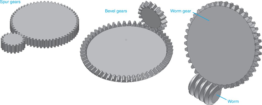
Figure 12-1
Gear Terminology
Pitch Diameter (D): The diameter used to define the spacing of gears. Ideally, gears are exactly tangent to each other along their pitch diameters.
Diametral Pitch (P): The number of teeth per inch. Meshing gears must have the same diametral pitch. Manufacturers’ gear charts list gears with the same diametral pitch.
Module (M): The pitch diameter divided by the number of teeth. The metric equivalent of diametral pitch.
Number of Teeth (N): The number of teeth of a gear.
Circular Pitch (CP): The circular distance from a fixed point on one tooth to the same position on the next tooth as measured along the pitch circle. The circumference of the pitch circle divided by the number of teeth.
Preferred Pitches: The standard sizes available from gear manufacturers. Whenever possible, use preferred gear sizes.
Center Distance (CD): The distance between the center points of two meshing gears.
Backlash: The difference between a tooth width and the engaging space on a meshing gear.
Addendum (a): The height of a tooth above the pitch diameter.
Dedendum (d): The depth of a tooth below the pitch diameter.
Whole Depth: The total depth of a tooth. The addendum plus the dedendum.
Working Depth: The depth of engagement of one gear into another. Equal to the sum of the two gears’ addendums.
Circular Thickness: The distance across a tooth as measured along the pitch circle.
Face Width (F): The distance from front to back along a tooth as measured perpendicular to the pitch circle.
Outside Diameter: The largest diameter of the gear. Equal to the pitch diameter plus the addendum.
Root Diameter: The diameter of the base of the teeth. Equal to the pitch diameter minus the dedendum.
Clearance: The distance between the addendum of the meshing gear and the dedendum of the mating gear.
Pressure Angle: The angle between the line of action and a line tangent to the pitch circle. Most gears have pressure angles of either 14.5° or 20°.
See Figure 12-2.

Figure 12-2
Gear Formulas
Figure 12-3 shows a chart of formulas commonly associated with gears. The formulas are for spur gears.

Figure 12-3
Drawing Gears Using the Gear Tool
Draw two gears with 60 and 120 teeth, respectively, a diametral pitch of 24, a pressure angle of 14.5°, and a face width of 0.75 in.
![]() Start a new drawing using the Standard (in).iam format.
Start a new drawing using the Standard (in).iam format.
![]() Click the Design tab.
Click the Design tab.
See Figure 12-4.
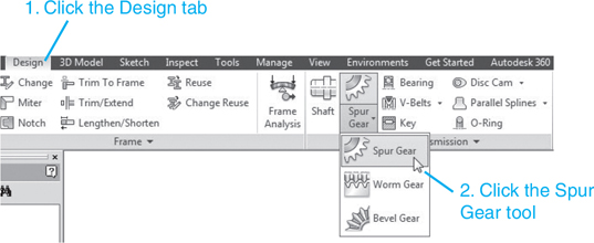
Figure 12-4
![]() Click the Spur Gear tool.
Click the Spur Gear tool.
Note
In metric units, diametral pitch is called module.
The Spur Gears Component Generator dialog box will appear. See Figure 12-5. There are several options available under the Design Guide option. The Center Distance option will be used for this example.

Figure 12-5
![]() Enter the following values.
Enter the following values.
Gear1: 60 teeth, facewidth = 0.75
Gear2: 120 teeth, facewidth = 0.500
Diametral pitch = 24 ul/in.
A gear ratio of 2.00 will be calculated automatically.
![]() Click Calculate, then click OK.
Click Calculate, then click OK.
The two gears will appear on the screen. See Figure 12-6.

Figure 12-6
![]() Click Spur Gears:1 in the browser box, right-click Spur Gear1:1, and click the Isolate option.
Click Spur Gears:1 in the browser box, right-click Spur Gear1:1, and click the Isolate option.
See Figure 12-7. Figure 12-8 shows the finished gear.

Figure 12-7
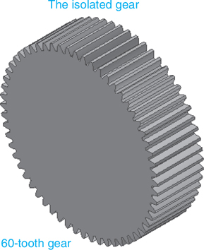
Figure 12-8
Gear Hubs
This section will show how to add a gear hub to a gear. The gear created and isolated in the last section and shown in Figure 12-8 will be used. A hub will be added, a hole will be created through the hub and gear, and a threaded hole for a setscrew will also be added.
Exercise 12-1 Adding a Hub to a Gear
![]() Move the cursor into the browser area, right-click Spur Gear1:1, and select the Edit option.
Move the cursor into the browser area, right-click Spur Gear1:1, and select the Edit option.
See Figure 12-9.
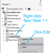
Figure 12-9
![]() Move the cursor onto the front face of the gear, right-click the mouse, and select the New Sketch option.
Move the cursor onto the front face of the gear, right-click the mouse, and select the New Sketch option.
See Figure 12-10.
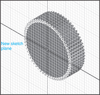
Figure 12-10
![]() Sketch a Ø1.250 circle on the gear.
Sketch a Ø1.250 circle on the gear.
See Figure 12-11.

Figure 12-11
![]() Right-click the mouse and select the Finish 2D Sketch option.
Right-click the mouse and select the Finish 2D Sketch option.
See Figures 12-12 and 12-13.
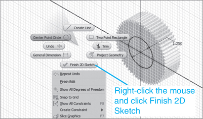
Figure 12-12
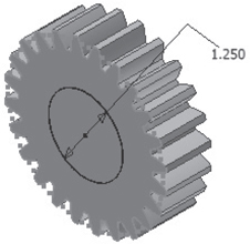
Figure 12-13
![]() Click the Extrude tool and extrude the Ø1.250 circle 0.75.
Click the Extrude tool and extrude the Ø1.250 circle 0.75.
See Figure 12-14.

Figure 12-14
![]() Create a new sketch plane on the top surface of the extrusion and locate a Point, Center Point.
Create a new sketch plane on the top surface of the extrusion and locate a Point, Center Point.
See Figure 12-15.
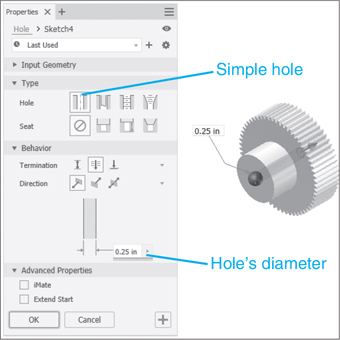
Figure 12-15
![]() Right-click the mouse again and select the Finish 2D Sketch option.
Right-click the mouse again and select the Finish 2D Sketch option.
![]() Click the Hole tool and add a simple Ø.500 hole through the hub and gear (Through All).Click OK.
Click the Hole tool and add a simple Ø.500 hole through the hub and gear (Through All).Click OK.
See Figure 12-16.

Figure 12-16
![]() Create an offset work plane tangent to the hub by clicking the Work Plane tool located on the flyout from the Plane tool on the Work Features panel under the 3D Model tab, clicking the XZ Plane under the Origin heading of Spur Gear1:1 in the browser box, and touching the edge of the hub’s outer surface with the cursor.
Create an offset work plane tangent to the hub by clicking the Work Plane tool located on the flyout from the Plane tool on the Work Features panel under the 3D Model tab, clicking the XZ Plane under the Origin heading of Spur Gear1:1 in the browser box, and touching the edge of the hub’s outer surface with the cursor.
See Figure 12-17.

Figure 12-17
Tip
The work plane is created by clicking the Work Plane tool then the XZ plane under the Origin heading in the browser box. Move the cursor to the outside surface of the hub. A work plane will appear tangent to the hub.
![]() Create a second offset work plane .375 above the first offset plane tangent to top edge of the hub. Create a new sketch plane and add a Point, Center Point located above the hub on its centerline. See Figure 12-18.
Create a second offset work plane .375 above the first offset plane tangent to top edge of the hub. Create a new sketch plane and add a Point, Center Point located above the hub on its centerline. See Figure 12-18.

Figure 12-18
Note that a construction line was added to enable the dimensioning.
![]() Right-click the mouse and select the Finish 2D Sketch option.
Right-click the mouse and select the Finish 2D Sketch option.
![]() Click the Hole tool and create a 10-24 UNC threaded hole in the hub. Hide the work plane.
Click the Hole tool and create a 10-24 UNC threaded hole in the hub. Hide the work plane.
Tip
Do not use the Through All distance, as this will create two holes.
See Figure 12-19. The #10 is a hole size. It is a Ø.19 hole.
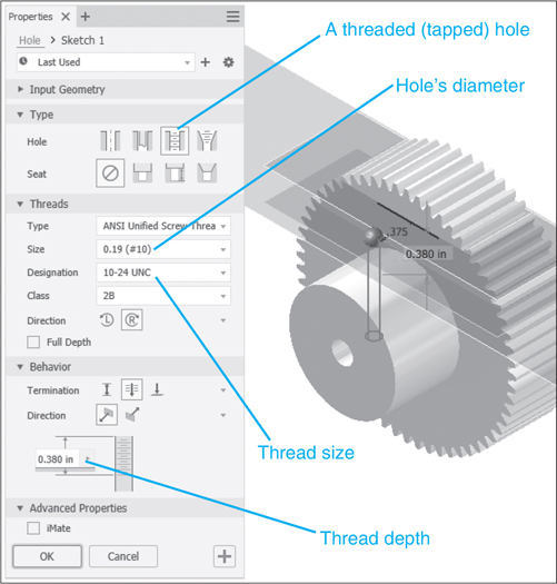
Figure 12-19
![]() Right-click Work Plane callouts in the Browser box and remove the check mark on the Visibility option on all the planes. See Figure 12-20.
Right-click Work Plane callouts in the Browser box and remove the check mark on the Visibility option on all the planes. See Figure 12-20.
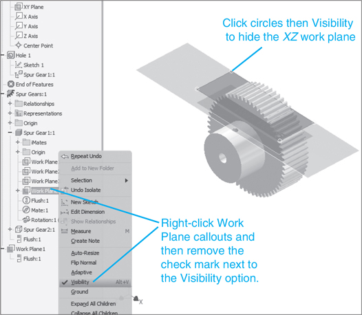
Figure 12-20
This will hide the XZ work plane.
![]() Click the Assemble tab and click the Design tab.
Click the Assemble tab and click the Design tab.
Figure 12-21 shows the finished gear.

Figure 12-21
![]() Click on the Place from Content Center tool.
Click on the Place from Content Center tool.
![]() Access the Set Screws and select Hexagon Socket Set Screw – Half Dog Point – Inch. Click OK.
Access the Set Screws and select Hexagon Socket Set Screw – Half Dog Point – Inch. Click OK.
See Figure 12-22.

Figure 12-22
![]() Select a #10 UNC thread that is 0.38 long. Click OK.
Select a #10 UNC thread that is 0.38 long. Click OK.
See Figure 12-23.
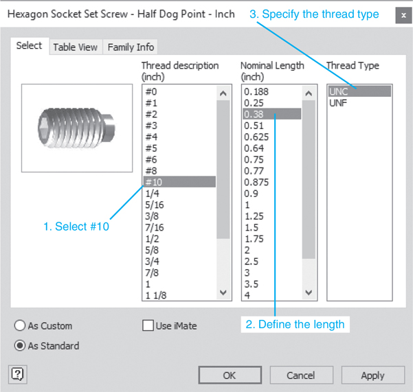
Figure 12-23
![]() Use the Constrain tool and position the setscrew.
Use the Constrain tool and position the setscrew.
See Figure 12-24.

Figure 12-24
Note
In this example, a work axis was created to help align the setscrew and the hole.
Gear Ratios
The speed ratio between two gears is determined by the number of teeth on each gear. For example, if two spur gears have 60 teeth and 20 teeth, respectively, the gear ratio is 60/20 = 3/1. See Figure 12-25. Thus, if the larger gear with 60 teeth is rotating at 30 revolutions per minute (RPM), the smaller gear with 20 teeth will rotate at 90 RPM. It is a general rule of thumb not to use spur gear ratios greater than 5:1.
The ratio of number of teeth on the larger of two meshing gears to the number on the smaller gear.
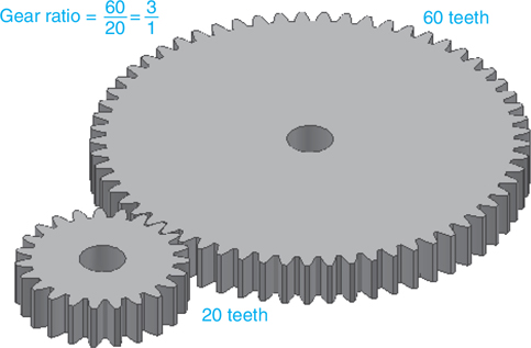
Figure 12-25
Bevel gear ratios are also determined by the number of teeth on each gear. Again, the general rule of thumb is not to use gear ratios greater than 5:1. See Figure 12-26.

Figure 12-26
The gear ratio for a worm and worm gear combination is determined by the number of teeth on the worm gear. The cylinder-shaped gear is called a worm, and the round gear is called a worm gear. The worm is assumed to be 1 tooth. If a worm gear is meshed with a worm, and the worm gear has 42 teeth, the gear ratio will be 42:1. See Figure 12-27.
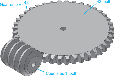
Figure 12-27
Gear Trains
When more than two gears are used in a design the combination is called a gear train. Figure 12-28 shows a gear train that contains four gears: two 20-tooth gears, one 40-tooth gear, and one 60-tooth gear. The speed ratio between the input RPM and output RPM is determined by multiplying the individual gear ratios together. Observe that the 40-tooth gear and one of the 20-tooth gears are mounted on the same shaft. There is no speed ratio between these two gears, as they have the same angular velocity. The speed ratio is
The combination of more than two meshing gears.
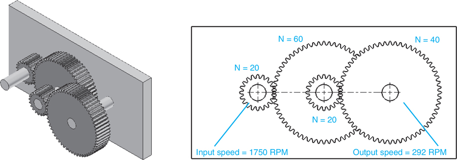
Figure 12-28
For an input speed of 1750 RPM, the output speed would be
Figure 12-29 shows another gear train that includes six gears: three 20-tooth gears and three 60-tooth gears. The speed ratio between input and output speeds is

Figure 12-29
For an input speed of 1750 RPM, the output speed would be
Gear Direction
Meshing gears always rotate in opposite directions. If gear 1 in Figure 12-29 were to rotate clockwise (CW), then gear 2 would rotate counterclockwise (CCW). Gear 3 would also rotate CCW, driving gear 4 in a CW direction. Gear 5 would rotate in the CW direction and drive gear 6 in the CCW direction. A gear called an idler may be added to a gear train for the sole purpose of changing the direction of the final rotation. Idler gears are usually identical with one of the gears with which they are meshing so as not to affect the final speed ratio. See Figure 12-30.
A gear added to a gear train for the sole purpose of changing the direction of the final rotation.

Figure 12-30
Gears with Keyways
Figure 12-31 shows a hubless spur gear. It is to be joined to a shaft using a square key. A keyway must be added to the gear. The gear has a bore of Ø.5000 in. and a face width of .500 in. Its pressure angle is 14.5, it has 48 teeth, and a diametral pitch of 24. It was drawn using the Gear tools on the Power Transmission panel under the Design tab, on a Standard (in).iam format drawing.
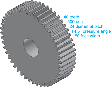
Figure 12-31
Exercise 12-2 Adding a Keyway to a Gear
First, determine the key that will be inserted into the gear. The information about the gear contained in the Content Center will specify the size of the keyway.
![]() Click the Place from Content Center tool.
Click the Place from Content Center tool.
See Figure 12-32.

Figure 12-32
![]() Select a Square key.
Select a Square key.
See Figure 12-33.

Figure 12-33
The bore of the gear is Ø.500, so the 0.43752 0.5625 shaft diameter range was selected, yielding a 1/8 × 1/8 width and height for the key. A nominal key length of 0.625 was selected.
![]() Click the Table View tab and access All Columns.
Click the Table View tab and access All Columns.
See Figure 12-34. The table specifies a Parallel Key Width of 0.125 and a Parallel Key Groove of 0.0625.
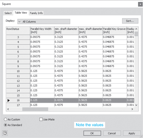
Figure 12-34
![]() Right-click the Gear callout in the browser box, select the Edit option, create a new sketch plane on the front surface of the gear, and draw a two-point rectangle as shown.
Right-click the Gear callout in the browser box, select the Edit option, create a new sketch plane on the front surface of the gear, and draw a two-point rectangle as shown.
See Figure 12-35. The .3130 value was derived from the bore radius of .250 and the Parallel Key Groove requirement of 0.0625. The width of the keyway is .125 (1/8).

Figure 12-35
![]() Right-click the mouse and select the Finish 2D Sketch option.
Right-click the mouse and select the Finish 2D Sketch option.
See Figure 12-36.

Figure 12-36
![]() Use the Extrude tool and cut out the rectangle, producing the keyway.
Use the Extrude tool and cut out the rectangle, producing the keyway.
See Figure 12-37.
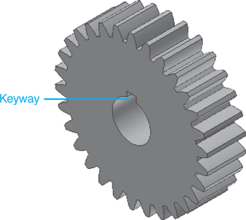
Figure 12-37
![]() Right-click the mouse and select the Finish Edit option.
Right-click the mouse and select the Finish Edit option.
![]() Assemble the square key into the gear’s keyway.
Assemble the square key into the gear’s keyway.
See Figure 12-38.

Figure 12-38
Note
Chapter 10 shows how to draw a keyway in a shaft.
Gear Assemblies
This section shows how to draw gear assemblies. Two meshing gears will be mounted onto a support plate using two shafts. The support plate and gear shafts were drawn using the dimensions shown in Figure 12-39. The Plate, Gear is 15 thick.

Figure 12-39
Exercise 12-3 Drawing a Gear Assembly
![]() Create a new drawing using the Standard (mm).iam format.
Create a new drawing using the Standard (mm).iam format.
![]() Access the Spur Gear tool on the Power Transmission panel under the Design tab.
Access the Spur Gear tool on the Power Transmission panel under the Design tab.
![]() Set the values for the dimensions of the gear in the Spur Gears Component Generator dialog box as shown in Figure 12-40.
Set the values for the dimensions of the gear in the Spur Gears Component Generator dialog box as shown in Figure 12-40.
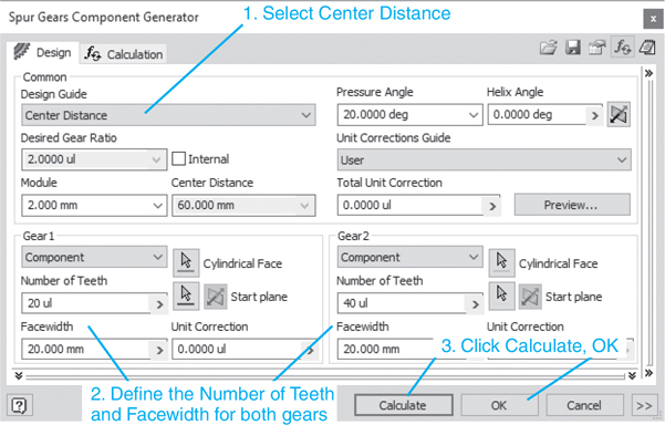
Figure 12-40
![]() Finish the gear drawing.
Finish the gear drawing.
Figure 12-41 shows the finished gears.
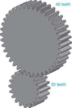
Figure 12-41
![]() Click the arrowhead next to the Spur Gears:1 heading in the browser box, right-click Spur Gear1:1, and select the Isolate option.
Click the arrowhead next to the Spur Gears:1 heading in the browser box, right-click Spur Gear1:1, and select the Isolate option.
![]() Right-click the 20-tooth gear and select the Edit option.
Right-click the 20-tooth gear and select the Edit option.
![]() Create a new sketch plane and draw a Ø20.00 circle. Right-click the mouse and select the Finish 2D Sketch option.
Create a new sketch plane and draw a Ø20.00 circle. Right-click the mouse and select the Finish 2D Sketch option.
See Figure 12-42.
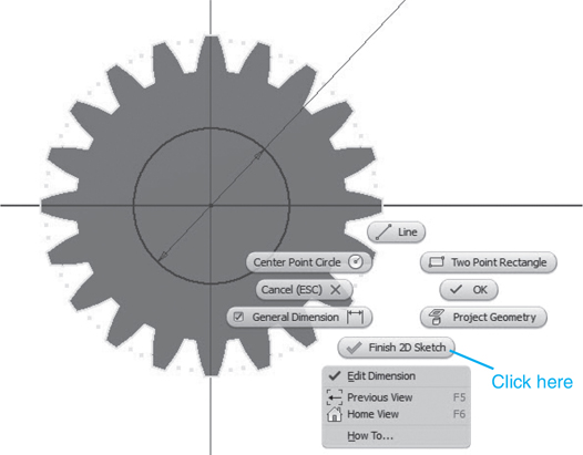
Figure 12-42
Note
See Exercise 12-1 for a more detailed explanation of how to draw gear hubs.
Tip
Do not select the Finish Edit option. Remember that you are working only on the 20-tooth gear, so you want to stay in that sketch mode.
![]() Extrude the Ø20 circle through a distance of 12 mm.
Extrude the Ø20 circle through a distance of 12 mm.
See Figure 12-43.

Figure 12-43
![]() Create a new sketch plane on the new top surface.
Create a new sketch plane on the new top surface.
See Figure 12-44.
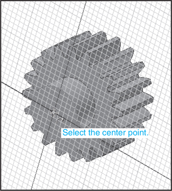
Figure 12-44
![]() Draw a Ø12.00 hole through the gear.
Draw a Ø12.00 hole through the gear.
See Figure 12-45.
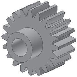
Figure 12-45
![]() Create a new work plane tangent to the gear’s hub. Locate a center point for a hole.
Create a new work plane tangent to the gear’s hub. Locate a center point for a hole.
See Figure 12-46.

Figure 12-46
![]() Draw a threaded hole. Use an M4 × 0.7 metric thread.
Draw a threaded hole. Use an M4 × 0.7 metric thread.
See Figure 12-47.
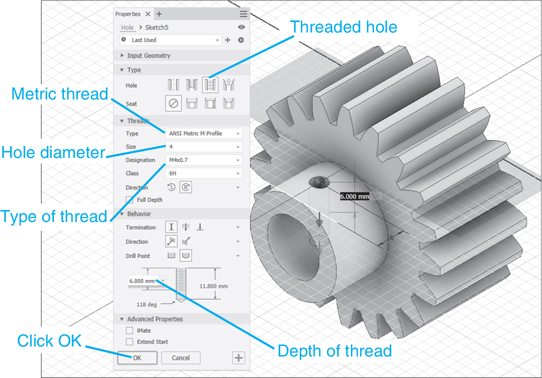
Figure 12-47
![]() Right-click the mouse and select the Finish Edit option.
Right-click the mouse and select the Finish Edit option.
![]() Right-click the mouse and click the Undo Isolate option.
Right-click the mouse and click the Undo Isolate option.
The 40-tooth gear will reappear.
See Figure 12-48.
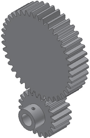
Figure 12-48
![]() Isolate the 40-tooth gear and create a hub, bore, and M4 × 0.7 threaded hole using the procedure described for the 20-tooth gear.
Isolate the 40-tooth gear and create a hub, bore, and M4 × 0.7 threaded hole using the procedure described for the 20-tooth gear.
See Figure 12-49.

Figure 12-49
![]() Save the two gears as Gear Subassembly.
Save the two gears as Gear Subassembly.
![]() Start a new drawing using the Standard (mm).iam format.
Start a new drawing using the Standard (mm).iam format.
Tip
You could have continued to work in the gear drawing and either inserted the existing components or created new components using the Create Component tool.
![]() Use the Place Component tool and insert a gear support plate, two shafts, and the gear subassembly.
Use the Place Component tool and insert a gear support plate, two shafts, and the gear subassembly.
See Figure 12-39 for dimensioned drawings of the plate and shafts.
See Figure 12-50.
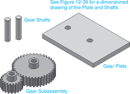
Figure 12-50
![]() Use the Constrain tool and assemble the gears, shafts, and support plate.
Use the Constrain tool and assemble the gears, shafts, and support plate.
See Figure 12-51.
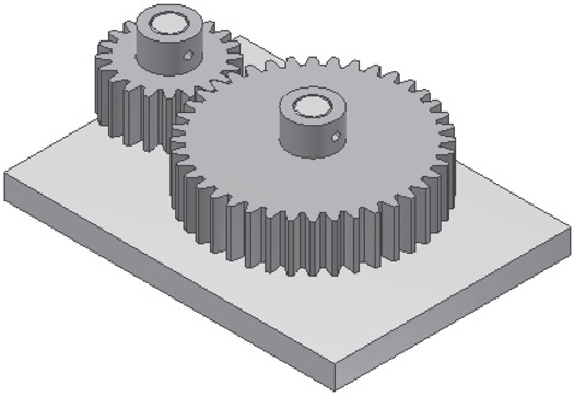
Figure 12-51
![]() Click the Place from Content Center tool located under the Assemble tab.
Click the Place from Content Center tool located under the Assemble tab.
Right-click the mouse and access the Content Center, click the Set Screws option, and select a DIN EN 24766 Set Screw with a point that has an M4 thread and is 4 long.
See Figures 12-52 and 12-53.

Figure 12-52
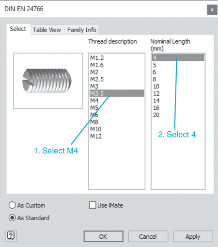
Figure 12-53
![]() Click OK.
Click OK.
Add two setscrews to the assembly drawing. See Figure 12-54.
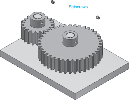
Figure 12-54
![]() Insert the setscrews into the gear hubs.
Insert the setscrews into the gear hubs.
Figure 12-55 shows the finished assembly.
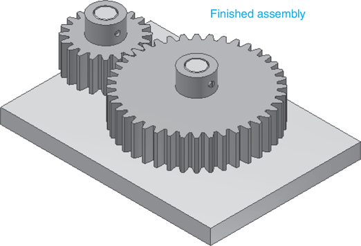
Figure 12-55
Tip
Use work planes and work axes if necessary to insert the setscrews into the hubs. Remember to assemble in the assembly drawing and not on individual components.
Bevel Gears
Bevel gears are conical-shaped gears that have intersecting axes. Spur gears have parallel axes. Figure 12-56 shows a set of meshing bevel gears.
Conical-shaped gears that have intersecting axes.

Figure 12-56
Exercise 12-4 Drawing Bevel Gears
Draw a set of bevel gears with 15 and 30 teeth, respectively. Define the module as 3.000, the shaft angle as 90°, the pressure angle as 20, and the face width as 20.00.
![]() Start a new drawing using the Standard (mm).iam format.
Start a new drawing using the Standard (mm).iam format.
![]() Click the Design tab, and click the Gear tool located on the Power Transmission panel.
Click the Design tab, and click the Gear tool located on the Power Transmission panel.
See Figure 12-57.

Figure 12-57
![]() Click the Bevel Gear tool.
Click the Bevel Gear tool.
The Bevel Gear option is a flyout from the Spur Gear tool. The Bevel Gear Component Generator dialog box will appear. See Figure 12-57.
![]() Enter 15 teeth for the small gear, 30 teeth for the large gear, and a Module value of 3.00.
Enter 15 teeth for the small gear, 30 teeth for the large gear, and a Module value of 3.00.
![]() Click Calculate.
Click Calculate.
![]() Click OK.
Click OK.
The File Naming box will appear.
![]() Click OK.
Click OK.
The gears will appear on the screen.
Exercise 12-5 Adding Hubs to Bevel Gears
![]() Rotate the gears so that the bottom surface of the small gear is in view.
Rotate the gears so that the bottom surface of the small gear is in view.
![]() Click the arrowhead to the left of the Bevel Gears:1 heading in the browser box, right-click on the Bevel Gear1:1 heading, and select the Edit option.
Click the arrowhead to the left of the Bevel Gears:1 heading in the browser box, right-click on the Bevel Gear1:1 heading, and select the Edit option.
See Figure 12-58.

Figure 12-58
![]() Create a new sketch plane on the bottom surface of the smaller gear.
Create a new sketch plane on the bottom surface of the smaller gear.
See Figure 12-59.

Figure 12-59
![]() Draw a Ø24 circle on the new sketch plane.
Draw a Ø24 circle on the new sketch plane.
![]() Right-click the mouse and select the Finish 2D Sketch option.
Right-click the mouse and select the Finish 2D Sketch option.
See Figure 12-60. Do not click the Finish Edit option. You are still working on the smaller gear, so continue working on the sketch.
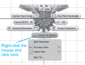
Figure 12-60
![]() Extrude the circle 12 mm.
Extrude the circle 12 mm.
![]() Right-click the mouse and create a new sketch plane on the top surface of the hub.
Right-click the mouse and create a new sketch plane on the top surface of the hub.
![]() Create a Ø12.00 hole Through All.
Create a Ø12.00 hole Through All.
![]() Right-click the mouse and select the Finish Edit option. Click the Isometric tool.
Right-click the mouse and select the Finish Edit option. Click the Isometric tool.
See Figure 12-61.

Figure 12-61
![]() Repeat the procedure for the larger gear. Make the hub 15 mm high with a Ø15 hole.
Repeat the procedure for the larger gear. Make the hub 15 mm high with a Ø15 hole.
See Figure 12-62. Figure 12-63 shows the finished bevel gears.
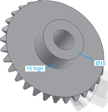
Figure 12-62
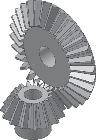
Figure 12-63
Exercise Adding Keyways to Bevel Gears
Before we can draw keyways, we must determine the size of the key. In the previous section, the gears were given bore diameters of Ø12 and Ø15, so keys must be selected to match those diameters.
![]() Click the Assemble tab and click the Place from Content Center tool.
Click the Assemble tab and click the Place from Content Center tool.
![]() Select the Shaft Parts option, Keys, Keys – Machine, and Rectangular.
Select the Shaft Parts option, Keys, Keys – Machine, and Rectangular.
![]() Select the DIN 6885 1B square key.
Select the DIN 6885 1B square key.
See Figure 12-64.

Figure 12-64
![]() Select the 10 - 12 shaft diameter input.
Select the 10 - 12 shaft diameter input.
This will generate a key size of 4× 4.
![]() Select a 20 nominal length.
Select a 20 nominal length.
See Figure 12-65.
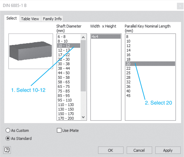
Figure 12-65
![]() Click the Table View tab.
Click the Table View tab.
See Figure 12-66.
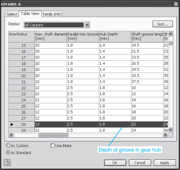
Figure 12-66
![]() Scroll the table to determine the recommended Hub Depth.
Scroll the table to determine the recommended Hub Depth.
In this example, the value is 1.8.
![]() Close the Content Center and return to the bevel gear drawing.
Close the Content Center and return to the bevel gear drawing.
![]() Select the smaller gear, right-click the mouse, and select the Edit option. Create a new sketch plane on the top surface of the gear.
Select the smaller gear, right-click the mouse, and select the Edit option. Create a new sketch plane on the top surface of the gear.
See Figure 12-67. Create a 2D view of the sketch plane if necessary.

Figure 12-67
![]() Draw a rectangle as shown.
Draw a rectangle as shown.
The width value of 4 matches the key width of 4 (no tolerances were factored in). The 7.8 value was derived from adding the bore’s radius (6.0) to the Hub Depth value given in the table (1.8). The keyway depth in the shaft is 2.5, for a total key size of 4.3, or slightly larger than the key height of 4. These values will vary when tolerances are considered.
![]() Right-click the mouse, click the Finish 2D Sketch option, click the Extrude tool, and cut the rectangle through the gear, producing a keyway.
Right-click the mouse, click the Finish 2D Sketch option, click the Extrude tool, and cut the rectangle through the gear, producing a keyway.
![]() Repeat the procedure for the larger gear.
Repeat the procedure for the larger gear.
![]() Right-click the mouse and select the Finish Edit option.
Right-click the mouse and select the Finish Edit option.
Figure 12-68 shows the finished keyways in the bevel gears.

Figure 12-68
Supports for Bevel Gears
Figure 12-69 shows a dimensioned drawing of the bevel gears created in the previous section. The drawing was created using the ANSI (mm).idw format. The two distances, 50.66 and 36.80, are needed to position the holes in the support structure.
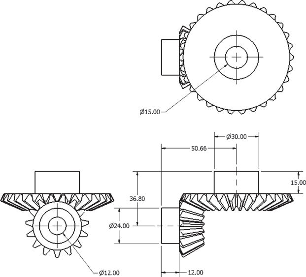
Figure 12-69
Exercise 12-7 Designing a Support Structure
![]() Draw an L-shape bracket.
Draw an L-shape bracket.
In this example, the horizontal portion of the bracket is 120 × 120 × 10, and the vertical portion is 100 × 120 × 10.
![]() Draw a Ø40 circle located as shown.
Draw a Ø40 circle located as shown.
See Figure 12-70. The 55.66 value is derived from the 50.66 center distance and an additional 5 for a boss.
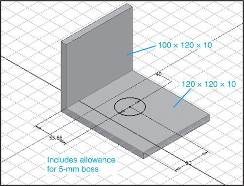
Figure 12-70
A boss is a raised area used to add additional support for gears and shafts. It also saves machining time, as only the surface of the boss is machined, not the entire surface.
A raised area used to add additional support for gears and shafts.
![]() Draw a boss 5 high with a Ø15 hole.
Draw a boss 5 high with a Ø15 hole.
See Figure 12-71.

Figure 12-71
![]() Draw a boss 5 high with a Ø12 hole on the vertical portion of the bracket.
Draw a boss 5 high with a Ø12 hole on the vertical portion of the bracket.
See Figures 12-72 and 12-73.
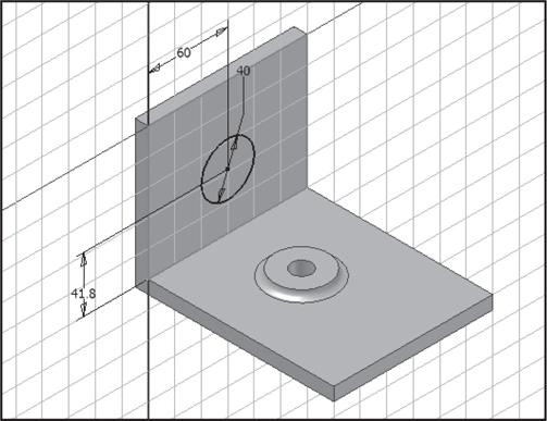
Figure 12-72
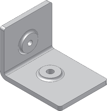
Figure 12-73
![]() Add any fillets required.
Add any fillets required.
![]() Use the Constrain tool and add the bevel gears to the support bracket.
Use the Constrain tool and add the bevel gears to the support bracket.
See Figure 12-74.
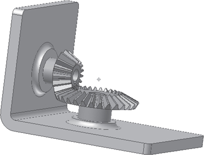
Figure 12-74
Worm Gears
Figure 12-75 shows a worm and a worm gear. Worm gear ratios are based on the fact that the worm has a value of 1. If the worm gear has 40 teeth, the gear ratio is 40:1.
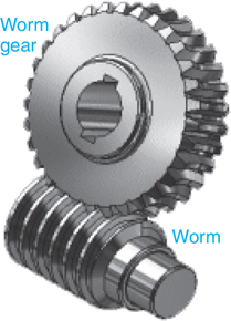
Figure 12-75
Exercise 12-8 Drawing a Worm and a Worm Gear
![]() Create a new drawing using the Standard (mm).iam format.
Create a new drawing using the Standard (mm).iam format.
![]() Click the Design tab, then click the Worm Gear tool on the Power Transmission panel.
Click the Design tab, then click the Worm Gear tool on the Power Transmission panel.
The Worm Gear tool is a flyout from the Spur Gear tool.
See Figure 12-76.

Figure 12-76
![]() Enter the values shown in Figure 12-76 and click OK.
Enter the values shown in Figure 12-76 and click OK.
In this example, the default values were accepted.
The File Naming dialog box will appear.
![]() Click OK.
Click OK.
Figure 12-77 shows the finished worm gears.
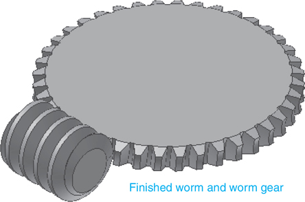
Figure 12-77
![]() Click the arrowhead to the left of the Worm Gears:1 heading in the browser box, right-click the Worm:1 heading, and select the Edit option.
Click the arrowhead to the left of the Worm Gears:1 heading in the browser box, right-click the Worm:1 heading, and select the Edit option.
See Figure 12-78.

Figure 12-78
![]() Right-click the end plane of the worm, create a new sketch plane on the end of the worm, and draw a Ø20 circle.
Right-click the end plane of the worm, create a new sketch plane on the end of the worm, and draw a Ø20 circle.
See Figure 12-79.
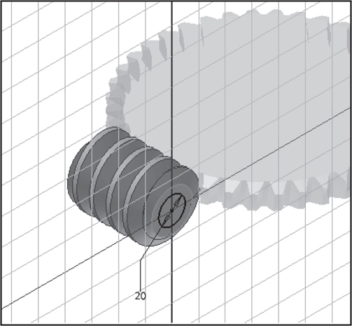
Figure 12-79
![]() Right-click the mouse and select the Finish 2D Sketch option.
Right-click the mouse and select the Finish 2D Sketch option.
![]() Extrude the Ø20 circle a distance of 24 to create a hub. Create a new sketch plane on the top surface of the hub and create a Ø12.0 hole.
Extrude the Ø20 circle a distance of 24 to create a hub. Create a new sketch plane on the top surface of the hub and create a Ø12.0 hole.
![]() Create a work plane tangent to the extruded hub.
Create a work plane tangent to the extruded hub.
See Figure 12-80.

Figure 12-80
![]() Add a threaded hole to the hub 10 from the top edge of the hub.
Add a threaded hole to the hub 10 from the top edge of the hub.
In this example, an M4 thread was added.
![]() Right-click the worm and select the Finish Edit option.
Right-click the worm and select the Finish Edit option.
![]() Add a Ø40 hub with a height of 20 and a Ø20.0 hole to the worm gear using the same procedure as was used for the worm. Create an M4 hole 10 from the top edge of the hub.
Add a Ø40 hub with a height of 20 and a Ø20.0 hole to the worm gear using the same procedure as was used for the worm. Create an M4 hole 10 from the top edge of the hub.
See Figure 12-81.
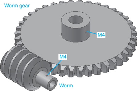
Figure 12-81
Supports for Worm Gears
Figure 12-82 shows orthographic views of a worm and worm gear drawn using the ANSI (mm).idw format. The Dimension tool was used to determine that the distance between their centers is 100.00 mm. A three-sided corner bracket was drawn. Each side of the bracket is 200 × 200 × 10, and the holes were located to match the 100.00 worm center requirement. Remember, the worm and the gear can be moved along the shafts to ensure correct alignment.
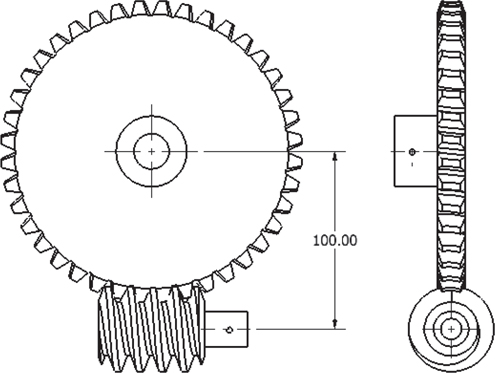
Figure 12-82
The corner bracket shown was created for clarity. It would be better to support the shafts at both ends with a boxlike structure.
Exercise 12-9 Drawing Worm Gear Supports
![]() Draw a corner bracket with two holes 100.00 apart.
Draw a corner bracket with two holes 100.00 apart.
Figure 12-83 shows two plates with two holes 100.00 apart vertically. Each side of the bracket is 200 × 200 × 10.

Figure 12-83
![]() Add the appropriate shafts.
Add the appropriate shafts.
See Figure 12-84.

Figure 12-84
![]() Use the Constrain tool and insert the worm gear assembly.
Use the Constrain tool and insert the worm gear assembly.
Figure 12-85 shows the finished worm gear assembly support.

Figure 12-85
Chapter Summary
This chapter explained the differences among three types of gears: spur, bevel, and worm. Gear terminology, formulas, and ratios were explained. The addition of hubs, splines, and keyways to gears was illustrated, and gears were assembled into gear trains.
Chapter Test Questions
Multiple Choice
Circle the correct answer.
1. What are the two components needed to create a worm gear assembly called?
a. Worm gear and spur gear
b. Worm and worm gear
c. Rack and worm gear
2. If a spur gear with 20 teeth is meshed with another spur gear with 50 teeth, what is the gear ratio?
a. 2:1
b. 1.75:1
c. 2.5:1
d. 3:1
3. If a worm is meshed with a worm gear that has 46 teeth, what is the gear ratio?
a. 46:1
b. 23:1
c. 192:1
d. 11:1
4. If four gears are meshed together and the first gear is turning clockwise, the fourth gear is turning
a. Clockwise
b. Counterclockwise
c. Dwelling
5. The hole in the center of a gear is called the
a. Center hole
b. Dedendum
c. Bore
d. Root diameter
6. The height of a tooth above the pitch diameter is called the
a. Face width
b. Dedendum
c. Addendum
d. Module
7. The diameter used to define the spacing of gears is called the
a. Pitch diameter
b. Diametral pitch
c. Preferred pitch
d. Center distance
8. A gear train is
a. A group of at least six gears
b. Any group of two or more meshing gears
c. A group of gears with different pitches
9. The portion of a gear that protrudes from the gear’s center and includes a bore is called the gear’s
a. Face
b. Hub
c. Backlash
d. Root fillet
10. A listing of setscrews and keys used with gears is found in the
a. Design tab
b. Assemble panel
c. Content Center
Matching
Match the terms in column A with the definition in column B.
Column A |
Column B |
|---|---|
a. Backlash ____________ |
1. The angle between the line of action and a line tangent to the pitch circle |
b. Circular thickness ____________ |
2. The pitch diameter divided by the number of teeth |
c. Module ____________ |
3. The distance across a tooth as measured along the pitch circle |
d. Pressure angle ____________ |
4. The distance from front to back along a tooth as measured perpendicular to the pitch circle |
e. Face width ____________ |
5. The difference between a tooth width and the engaging space on a meshing gear |
True or False
Circle the correct answer.
1. True or False: A library of gears is included in the Content Center.
2. True or False: Gears must have the same pitch to mesh properly.
3. True or False: The term pitch, as used with gears manufactured using English units, is called module for gears manufactured using metric units.
4. True or False: Diametral pitch is the outside diameter of a gear.
5. True or False: Gear ratios are determined by the number of teeth on each gear.
6. True or False: The axes of beveled gears are located at 90° to each other.
7. True or False: Bevel gears can mesh with spur gears.
8. True or False: Worms have a ratio value of 1 when meshing with worm gears.
9. True or False: A boss is a turretlike shape usually added to castings.
10. True or False: The face width of a gear is its thickness.
Chapter Projects
Project 12-1: Inches
Draw two spur gears based on the following parameters. Locate the two threaded holes 90° apart as shown. On both gears the threaded hole is located halfway up the hub height.
See Figure P12-1.
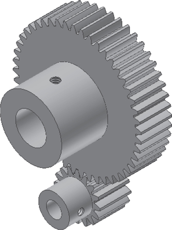
Figure P12-1
Project 12-2: Inches
A. Draw two spur gears based on the following parameters. On both gears the threaded hole is located halfway up the hub height.
B. Design Exercise
Create a support plate and shafts for the two gears drawn in part A of this project. See the section on gear assemblies. Create two shafts, Ø.500 and Ø1.000, with .05 chamfers at each end. The shafts should be long enough to allow for at least .25 clearance between the gears and the support plate. The shafts should extend from the bottom surface of the plate to the top surface of each gear’s hub.
Create a plate .375 thick. Size the plate so that it extends at least .25 beyond the edges on either gear. Mount the shafts in SKF Series RLS ball bearings, and create holes in the plate that will accommodate the outside diameters of the bearings.
See Figure P12-2.

Figure P12-2
Project 12-3: Millimeters
Draw two spur gears based on the following parameters. The threaded hole on both gears is located halfway up the hub height.
See Figure P12-3.

Figure P12-3
Project 12-4: Millimeters
A. Draw two spur gears based on the following parameters. The threaded hole on both gears is located halfway up the hub height.
See Figure P12-4.

Figure P12-4
B. Design Exercise
Create a support plate and shafts for the two gears drawn in part A of this project. See the section on gear assemblies. Create two shafts, Ø8.0 and Ø16.0, with 0.50 chamfers at each end. The shafts should be long enough to allow for at least 5.0 clearance between the gears and the support plate. The shafts should extend from the bottom surface of the plate to the top surface of each gear’s hub.
Create a plate 10 thick. Size the plate so that it extends at least 5.0 beyond the edges on either gear. Mount the shafts in DIN 1854-4 M plain bearings and create holes in the plate that will accommodate the outside diameters of the bearings.
Project 12-5: Inches
A. Draw two bevel gears based on the following parameters. The threaded hole on both gears is located halfway up the hub height.
|
Gear 1 |
Gear 2 |
|---|---|---|
Shaft angle |
90 |
90 |
Pressure angle |
20 |
20 |
Helix angle |
20 |
20 |
Number of teeth |
24 |
60 |
Face width |
.50 |
.50 |
Diametral pitch |
16 |
16 |
Hub Ø |
1.00 |
1.00 |
Hub height |
.75 |
.75 |
Bore |
.50 |
.50 |
Threaded hole |
#8-UNC |
#8-UNC |
B. Design Exercise
Create an L-bracket support plate and shafts for the two gears drawn in part A of this project. See the section on supports for bevel gears. Create two shafts, Ø.50 each, with .05 chamfers at each end. The shafts should be long enough to allow for at least .25 clearance between the gears and the support plate. The shafts should extend from the bottom surface of the plate to the top surface of each gear’s hub.
Create an L-bracket .375 thick. Size the bracket so that it extends at least .25 beyond the edges on either gear. Make the outside diameters of the bosses at least .025 greater than the outside diameter of the bearings. Make the bosses .25 high.
Mount the shafts in SKF Series RLS ball bearings, and create holes in the plate that will accommodate the outside diameters of the bearings.
Project 12-6: Millimeters
A. Draw two bevel gears based on the following parameters. The threaded hole on both gears is located halfway up the hub height.
|
Gear 1 |
Gear 2 |
|---|---|---|
Shaft angle |
90 |
90 |
Pressure angle |
20 |
20 |
Helix angle |
20 |
20 |
Number of teeth |
20 |
40 |
Face width |
12 |
12 |
Tangential module |
2 |
2 |
Hub Ø |
20 |
40 |
Hub height |
16 |
20 |
Bore |
12 |
20 |
Threaded hole |
M5 |
M6 |
B. Design Exercise
Create an L-bracket support plate and shafts for the two gears drawn in part A of this project. See the section on supports for bevel gears. Create two shafts, Ø12.0 and Ø20.0, with 0.50 chamfers at each end. The shafts should be long enough to allow for at least 5.0 clearance between the gears and the support plate. The shafts should extend from the bottom surface of the plate to the top surface of each gear’s hub.
Create an L-bracket 10 thick. Size the plate so that it extends at least 5.0 beyond the edges on either gear. Make the outside diameters of the bosses at least 5 greater than the outside diameter of the bearings. Make the bosses 5.00 high.
Mount the shafts in DIN 1854-4 M plain bearings, and create holes in the plate that will accommodate the outside diameters of the bearings.
Project 12-7: Inches
A. Draw a worm and a worm gear based on the following parameters. The threaded hole on both gears is located halfway up the hub height.
Worm gear: Number of teeth = 48 |
|
|
Worm: Number of threads = 1 |
|
|
|
Worm |
Worm Gear |
Face width |
|
.75 |
Diametral pitch |
12 |
12 |
Pressure angle |
20 |
20 |
Worm length |
2.50 |
|
Hub Ø |
.50 |
.50 |
Hub height |
.500 |
.750 |
Bore |
.375 |
.500 |
Threaded hole |
0.138(#6)UNC |
0.164(#8)UNC |
B. Design Exercise
Create a corner-bracket support plate and shafts for the two gears drawn in part A of this project. See the section on worm gear supports. Create two shafts, Ø.375 and Ø.500, with .05 chamfers at each end. The shafts should be long enough to allow for at least .25 clearance between the gears and the support plate. The shafts should extend from the back surface of the plate to the top surface of each gear’s hub.
Create a corner bracket .375 thick. Size the bracket so that it extends at least .25 beyond the edges on either gear. Mount the shafts in SKF Series RLS ball bearings and create holes in the sides that will accommodate the outside diameters of the bearings.
Project 12-8: Inches
A. Draw a worm and a worm gear based on the following parameters. The threaded hole on both gears is located halfway up the hub height.
Worm gear: Number of teeth = 60 |
|
|
Worm: Number of threads = 1 |
|
|
|
Worm |
Worm Gear |
Face width |
|
24 |
Module |
4 |
4 |
Pressure angle |
14.5 |
14.5 |
Worm length |
65 |
|
Hub Ø |
16 |
24 |
Hub height |
12 |
16 |
Bore |
8.0 |
10.0 |
Threaded hole |
M4 |
M4 |
B. Design Exercise
Create a corner-bracket support plate and shafts for the two gears drawn in part A of this project. See the section on worm gear supports. Create two shafts, Ø8.0 and Ø10.0, with .50 chamfers at each end. The shafts should be long enough to allow for at least 5.0 clearance between the gears and the support plate. The shafts should extend from the back surface of the plate to the top surface of each gear’s hub.
Create a corner bracket 8.0 thick. Size the bracket so that it extends at least 6.0 beyond the edges on either gear. Mount the shafts in DIN 1854-4 M plain bearings, and create holes in the sides that will accommodate the outside diameters of the bearings.
Project 12-9: Inches
A. Prepare an assembly drawing of the 2-Gear Assembly shown in Figure P12-9. The gears have the following parameters:
Center distance = 3.00 |
|
|
|
Gear 1 |
Gear 2 |
Number of teeth |
48 |
96 |
Face width |
.50 |
.50 |
Diametral pitch |
24 |
24 |
Pressure angle |
20 |
20 |
Hub Ø |
.750 |
1.000 |
Hub height |
.500 |
.500 |
Bore |
.5.00 |
.625 |
B. Prepare a presentation drawing.
C. Animate the presentation drawing.
D. Prepare an exploded isometric drawing with assembly numbers and a parts list.
E. Prepare a detailed dimensioned drawing of each part.

Figure P12-9A
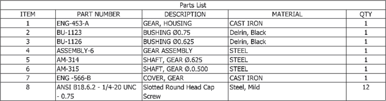
Figure P12-9B
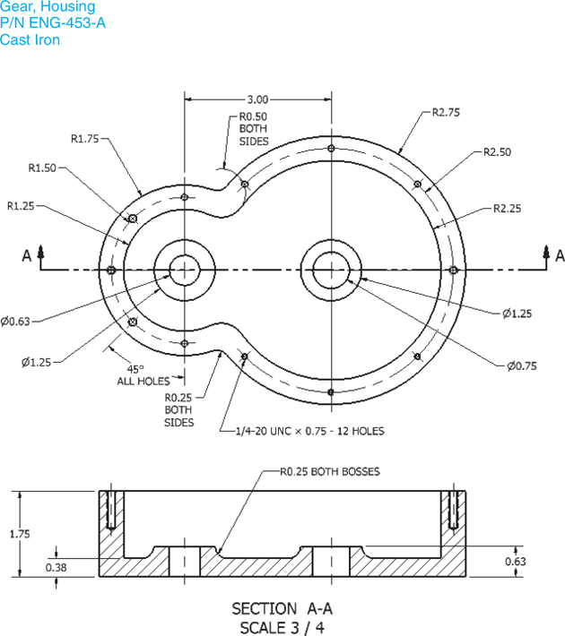
Figure P12-9C
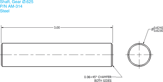
Figure P12-9D
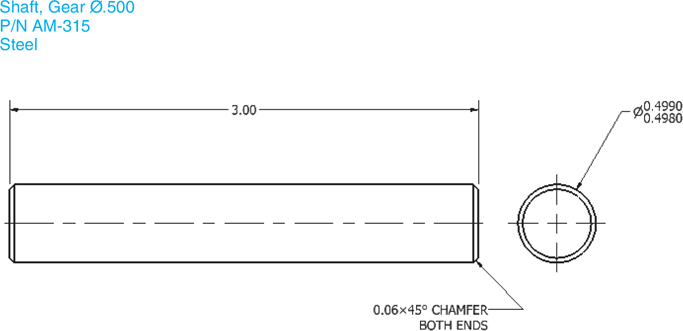
Figure P12-9E
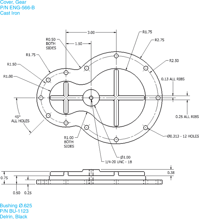
Figure P12-9F

Figure P12-9G

Figure P12-9H

Figure P12-9I
Project 12-10: Millimeters
A. Prepare an assembly drawing of the 4-Gear Assembly shown in Figure P12-10. The gears have the following parameters:
Center distance = 3.00 |
|
|
|
Gears 1, 3 |
Gears 2, 4 |
Number of teeth |
30 |
96 |
Face width |
20.0 |
20.0 |
Module |
2 |
2 |
Pressure angle |
20 |
20 |
Hub Ø |
50.0 |
60.0 |
Hub height |
20.0 |
20.0 |
Bore |
25.0 |
30.0 |
B. Prepare a presentation drawing.
C. Animate the presentation drawing.
D. Prepare an exploded isometric drawing with assembly numbers and a parts list.
E. Prepare a detailed dimensioned drawing of each part.

Figure P12-10A
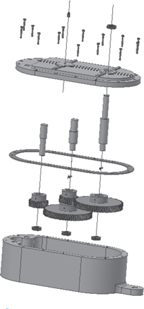
Figure P12-10B

Figure P12-10C
Figure P12-10D
Figure P12-10E
Figure P12-10F

Figure P12-10G
Figure P12-10H

Figure P12-10I
Figure P12-10J
Figure P12-10K