Chapter Nine. Springs
Chapter Objectives
Learn how to draw springs using the Coil tool and the tools on the Spring panel under the Design tab
Learn how to draw compression springs
Learn how to draw extension springs
Learn how to draw torsion springs
Learn how to draw Belleville springs
Introduction
This chapter shows how to draw springs. Both the Coil tool and the tools from the Spring panel are used to draw springs. Compression, extension, torsion, and Belleville springs are introduced.
Compression Springs
Exercise 9-1 Drawing a Compression Spring Using the Coil Tool
![]() Start a new metric drawing using the Standard (mm).ipt format, select the Create 2D Sketch option and select the XY plane.
Start a new metric drawing using the Standard (mm).ipt format, select the Create 2D Sketch option and select the XY plane.
![]() Create an isometric view (use the Home tool next to the ViewCube) and draw a line and a circle as shown in Figure 9-1.
Create an isometric view (use the Home tool next to the ViewCube) and draw a line and a circle as shown in Figure 9-1.

Figure 9-1
The circle diameter is the wire’s diameter (5), and the distance between the line and the center point of the circle equals the spring’s mean diameter (Ø20, R = 10).
![]() Right-click the mouse and select the Finish 2D Sketch option.
Right-click the mouse and select the Finish 2D Sketch option.
![]() Select the Coil tool on the Create panel under the 3D Model tab.
Select the Coil tool on the Create panel under the 3D Model tab.
The Coil dialog box will appear. See Figure 9-2.

Figure 9-2
![]() Select the circle as the Profile and the line as the Axis.
Select the circle as the Profile and the line as the Axis.
![]() Click on the Coil Size tab on the Coil dialog box.
Click on the Coil Size tab on the Coil dialog box.
See Figure 9-3.

Figure 9-3
![]() Set the Pitch value for 8 and the Revolution for 6.
Set the Pitch value for 8 and the Revolution for 6.
![]() Click OK.
Click OK.
See Figure 9-4.

Figure 9-4
Coil Ends
The ends of a spring created using the Coil tool can be drawn in one of two ways: natural or flat. Figure 9-5 shows three different possible coil end configurations.

Figure 9-5
Exercise 9-2 Changing the End of a Spring
![]() Click the Coil Ends tab on the Coil dialog box.
Click the Coil Ends tab on the Coil dialog box.
See Figure 9-6. The spring shown in Figure 9-4 has natural ends. Springs with flat ends must have their transition and flat angles defined, as was done in Figure 9-5.

Figure 9-6
Exercise 9-3 Drawing a Compression Spring Using Design Accelerator Options
![]() Start a new drawing using the English tab.
Start a new drawing using the English tab.
![]() Select the Standard (in).iam format.
Select the Standard (in).iam format.
The Assemble panels will appear. See Figure 9-7.

Figure 9-7
![]() Click the Design tab.
Click the Design tab.
![]() Select the Compression tool located on the Spring panel under the Design tab.
Select the Compression tool located on the Spring panel under the Design tab.
The Compression Spring Component Generator dialog box will appear. See Figure 9-8.

Figure 9-8
![]() Enter values for both the Spring Start and Spring End as follows:
Enter values for both the Spring Start and Spring End as follows:
Closed End Coils = 2.000
Transition Coils = 1.000
Ground Coils = 0.750
![]() Click the Calculation tab.
Click the Calculation tab.
The dialog box will change. See Figure 9-9.

Figure 9-9
![]() Set the Spring Strength Calculation for Work Forces Calculation.
Set the Spring Strength Calculation for Work Forces Calculation.
![]() Accept the calculated default value.
Accept the calculated default value.
![]() Click Calculate, and click OK.
Click Calculate, and click OK.
Figure 9-10 shows the finished compression spring.

Figure 9-10
Tip
The spring’s ends are square ground. Square-ground ends sit better on flat surfaces and tend not to buckle when put under a load.
Exercise 9-4 Drawing a Ground End on a Compression Spring Drawn Using the Coil Tool
Figure 9-11 shows a compression spring that was drawn using the Coil tool.

Figure 9-11
![]() Create a work plane through one of the end coils.
Create a work plane through one of the end coils.
See Figure 9-12. In this example, an XZ work plane was created offset 4.00 from the end of the spring.

Figure 9-12
![]() Create a new sketch plane on the work plane. Draw a rectangle on the new sketch plane. Size the rectangle so that it is larger than the outside diameter of the spring.
Create a new sketch plane on the work plane. Draw a rectangle on the new sketch plane. Size the rectangle so that it is larger than the outside diameter of the spring.
See Figure 9-13.

Figure 9-13
![]() Right-click the mouse and select the Extrude tool. Extrude the rectangle so that it extends beyond the end of the spring.
Right-click the mouse and select the Extrude tool. Extrude the rectangle so that it extends beyond the end of the spring.
In this example, an extrusion value of 10 was used. See Figure 9-14.

Figure 9-14
![]() Use the Cut option of the Extrude tool and cut out the extruded rectangle.
Use the Cut option of the Extrude tool and cut out the extruded rectangle.
Figure 9-15 shows the finished spring.

Figure 9-15
Extension Springs
Exercise 9-5 Drawing an Extension Spring Using Tools on the Spring Panel
![]() Start a new drawing using English units and the Standard (in).ipm format.
Start a new drawing using English units and the Standard (in).ipm format.
![]() Click the Design tab.
Click the Design tab.
See Figure 9-16.

Figure 9-16
![]() Click the Extension tool on the Spring panel.
Click the Extension tool on the Spring panel.
The Extension Spring Component Generator dialog box will appear. See Figure 9-17.

Figure 9-17
![]() Set the following values and inputs:
Set the following values and inputs:
Coil Direction = right
Wire Diameter = 0.125
Diameter, Outer = 1.000
Start Hook Type = Full Loop
Start Hook Length = 0.800
End Hook Type = Full Loop
End Hook Length = 0.800
Length Inputs = n, o --> L0
n = 12.000
t = 0.25
![]() Click the Calculate box at the bottom of the screen. See Figure 9-17.
Click the Calculate box at the bottom of the screen. See Figure 9-17.
![]() Click OK.
Click OK.
The File Naming dialog box will appear.
![]() Click OK.
Click OK.
The finished extension spring will appear. See Figure 9-18.

Figure 9-18
Tip
If an input error is made, a red line will appear across the bottom of the screen when OK is clicked, and the incorrect value will be highlighted.
Exercise 9-6 Drawing an Extension Spring Using the Coil Tool
![]() Start a new drawing using the Standard (mm).ipt format, select the Create 2D Sketch option, and select the XY plane.
Start a new drawing using the Standard (mm).ipt format, select the Create 2D Sketch option, and select the XY plane.
![]() Use the Home tool to orient the drawing to an isometric view and draw a Ø5-mm circle 15 mm from a line.
Use the Home tool to orient the drawing to an isometric view and draw a Ø5-mm circle 15 mm from a line.
See Figure 9-19.

Figure 9-19
![]() Right-click the mouse and select Finish 2D Sketch option. Select the Coil tool.
Right-click the mouse and select Finish 2D Sketch option. Select the Coil tool.
The Coil dialog box will appear. See Figure 9-20.

Figure 9-20
![]() Select the circle as the Profile and the line as the Axis. Click the Coil Size tab.
Select the circle as the Profile and the line as the Axis. Click the Coil Size tab.
![]() Set the Pitch for 15, the Revolution for 6.00, and the Taper for 0.00. Click the Coil Ends tab.
Set the Pitch for 15, the Revolution for 6.00, and the Taper for 0.00. Click the Coil Ends tab.
See Figure 9-21.

Figure 9-21
![]() Set the Start for Flat and both the Transition Angle and Flat Angle for 90°. Set the End for Flat and the Transition Angle and Flat Angle for 0.00°. Click OK.
Set the Start for Flat and both the Transition Angle and Flat Angle for 90°. Set the End for Flat and the Transition Angle and Flat Angle for 0.00°. Click OK.
See Figure 9-22. The finished spring will appear. See Figure 9-23.

Figure 9-22

Figure 9-23
![]() Use the Free Orbit tool located on the right edge of the screen and rotate the spring so that the start end is completely visible.
Use the Free Orbit tool located on the right edge of the screen and rotate the spring so that the start end is completely visible.
See Figure 9-24.

Figure 9-24
![]() Create a new sketch plane aligned with the start end of the spring.
Create a new sketch plane aligned with the start end of the spring.
See Figure 9-25.

Figure 9-25
![]() Right-click the mouse and select the Finish 2D Sketch option. Create an XY work plane aligned with the start end of the spring.
Right-click the mouse and select the Finish 2D Sketch option. Create an XY work plane aligned with the start end of the spring.
To create an XY work plane, click on the Plane tool on the Work Features panel, then on the XY Plane tool located under the Origin heading under Part name in the browser box, and click the start end’s center point.
See Figure 9-26.

Figure 9-26
![]() Add a YZ work plane through the center point of the spring’s start end.
Add a YZ work plane through the center point of the spring’s start end.
The YZ work plane is created by clicking the Work Plane tool, clicking the YZ Plane tool located under the Origin heading under the Part Name in the browser box, and clicking the starting end’s center point.
See Figure 9-27.

Figure 9-27
![]() Create a new sketch plane on the YZ work plane and draw a Ø5 circle centered on the spring’s start end.
Create a new sketch plane on the YZ work plane and draw a Ø5 circle centered on the spring’s start end.
See Figure 9-28. Use the Free Orbit and Zoom tools to orient and enlarge the end planes so they are clearly visible.

Figure 9-28
![]() Right-click the mouse and select the Finish 2D Sketch option. Extrude the Ø5 circle 12 mm away from the spring.
Right-click the mouse and select the Finish 2D Sketch option. Extrude the Ø5 circle 12 mm away from the spring.
See Figure 9-29.

Figure 9-29
![]() Rotate the spring and use the Loft tool to fill in the area between the extruded cylinder and the spring’s start end.
Rotate the spring and use the Loft tool to fill in the area between the extruded cylinder and the spring’s start end.
See Figure 9-30.

Figure 9-30
![]() Create a new sketch plane on the end of the 12-mm extrusion created in step 12. Draw a Ø5 circle centered about the center point of the extrusion’s end.
Create a new sketch plane on the end of the 12-mm extrusion created in step 12. Draw a Ø5 circle centered about the center point of the extrusion’s end.
See Figure 9-31.

Figure 9-31
![]() Create a fixed work point on the extrusion’s center point as shown. Create a new sketch plane on the XY work plane and draw a 15-mm, 180° arc using the Center Point Arc tool, which is located on the Draw panel under the Sketch tab.
Create a fixed work point on the extrusion’s center point as shown. Create a new sketch plane on the XY work plane and draw a 15-mm, 180° arc using the Center Point Arc tool, which is located on the Draw panel under the Sketch tab.
See Figure 9-32. Use the background grid and visually align the arc’s center point with the extrusion’s center point.

Figure 9-32
![]() Use the Sweep tool to draw the spring’s hooked end.
Use the Sweep tool to draw the spring’s hooked end.
See Figures 9-33 and 9-34.

Figure 9-33

Figure 9-34
![]() Apply the same procedure to the other end of the spring.
Apply the same procedure to the other end of the spring.
See Figures 9-35 and 9-36.

Figure 9-35

Figure 9-36
Torsion Springs
Exercise 9-7 Drawing a Torsion Spring Using Tools on the Spring Panel
![]() Start a new drawing using the Standard (in).iam format.
Start a new drawing using the Standard (in).iam format.
The Assemble panels will appear.
![]() Click the Design tab and select the Torsion tool located on the Spring panel.
Click the Design tab and select the Torsion tool located on the Spring panel.
The Torsion Spring Component Generator dialog box will appear. See Figure 9-37.

Figure 9-37
![]() Enter the following values:
Enter the following values:
Coil Direction = right
Wire Diameter = 0.125
Diameter, Outer = 1.2883
Start Arm Length = 1.25
End Arm Length = 1.00
Length Inputs = t, n --> L0
Active Coils Number = 14
![]() Click OK.
Click OK.
The File Naming dialog box will appear. See Figure 9-38.

Figure 9-38
![]() Click OK.
Click OK.
Figure 9-39 shows the finished torsion spring.

Figure 9-39
Exercise 9-8 Drawing a Torsion Spring Using the Coil Tool
![]() Start a new drawing using the Standard (mm).ipt format, select the Create 2D Sketch option, and select the XY plane.
Start a new drawing using the Standard (mm).ipt format, select the Create 2D Sketch option, and select the XY plane.
![]() Use the Home tool and create an isometric orientation. Define a wire diameter of 6 mm and a mean diameter of 32 mm.
Use the Home tool and create an isometric orientation. Define a wire diameter of 6 mm and a mean diameter of 32 mm.
![]() Right-click the mouse and select the Finish 2D Sketch option.
Right-click the mouse and select the Finish 2D Sketch option.
See Figure 9-40.

Figure 9-40
![]() Access the Coil tool, define the Profile and Axis, click the Coil Size tab, and set the Pitch for 10 and the Revolution for 8.
Access the Coil tool, define the Profile and Axis, click the Coil Size tab, and set the Pitch for 10 and the Revolution for 8.
See Figure 9-41.

Figure 9-41
![]() Set the Start for Flat and the Transition Angle and Flat Angle of 90°. Set the End for Flat and the Transition Angle and Flat Angle for 45°.
Set the Start for Flat and the Transition Angle and Flat Angle of 90°. Set the End for Flat and the Transition Angle and Flat Angle for 45°.
See Figure 9-42.

Figure 9-42
![]() Use the Free Orbit tool and rotate the spring to access the start end. Create a new sketch plane on the end. Draw a Ø6-mm circle on the end centered on the end’s center point.
Use the Free Orbit tool and rotate the spring to access the start end. Create a new sketch plane on the end. Draw a Ø6-mm circle on the end centered on the end’s center point.
See Figure 9-43.

Figure 9-43
![]() Right-click the mouse and select the Finish 2D Sketch option. Extrude the start end 50 mm.
Right-click the mouse and select the Finish 2D Sketch option. Extrude the start end 50 mm.
See Figure 9-44.

Figure 9-44
![]() Extrude the other spring end 50 mm.
Extrude the other spring end 50 mm.
Figure 9-45 shows the finished spring.

Figure 9-45
Belleville Springs
A Belleville spring is a disk-like device that resists bending. Belleville springs can be stacked together, all bending in the same direction, or stacked in opposition. The tools on the Spring panel can be used to generate either condition.
A disk-like device that resists bending; springs can be stacked bending in the same direction or in opposition.
Exercise 9-9 Drawing a Belleville Spring Using Tools on the Spring Panel
![]() Start a new drawing using the Standard (in).iam format.
Start a new drawing using the Standard (in).iam format.
![]() Click the Design tab and select the Belleville tool on the Spring panel.
Click the Design tab and select the Belleville tool on the Spring panel.
The Belleville Spring Generator dialog box will appear. See Figure 9-46.

Figure 9-46
![]() Click on the arrow to the right of the Single-disk Spring Dimensions heading.
Click on the arrow to the right of the Single-disk Spring Dimensions heading.
A list of options will cascade down.
![]() Select the 3.000 in × 1.500 in × 0.100 in × 0.175 in option.
Select the 3.000 in × 1.500 in × 0.100 in × 0.175 in option.
See Figure 9-47.

Figure 9-47
![]() Enter the Height value.
Enter the Height value.
In this example, a value of 0.16 was used. See Figure 9-48.

Figure 9-48
![]() Click OK.
Click OK.
The File Naming dialog box will appear.
![]() Click OK.
Click OK.
The finished spring will appear. See Figure 9-49. Figure 9-50 shows orthographic views of the spring.

Figure 9-49

Figure 9-50
Springs in Assembly Drawings
Figure 9-51 shows five components that are to be assembled together. The drawing was created using the Standard (in).iam format, and the springs were created using tools from the Spring panel.

Figure 9-51
Figure 9-52 shows dimensioned drawings of the Blocks and the Post. Figure 9-53 shows the values used with the Compression Spring Component Generator dialog box.

Figure 9-52

Figure 9-53
The assembly procedure presented here represents one of several possible procedures.
Exercise 9-10 Creating a Work Axis on the Front Block
![]() Right-click on the Front Block and select the Edit option.
Right-click on the Front Block and select the Edit option.
The other components will fade to a lighter color.
![]() Create a work axis through the center point of the through hole.
Create a work axis through the center point of the through hole.
![]() Create a new sketch plane aligned with the bottom surface of the shallow hole. Click the right mouse button and select the Finish 2D Sketch (not Finish Edit) option. Create a work point on the center point of the shallow hole.
Create a new sketch plane aligned with the bottom surface of the shallow hole. Click the right mouse button and select the Finish 2D Sketch (not Finish Edit) option. Create a work point on the center point of the shallow hole.
See Figure 9-54.
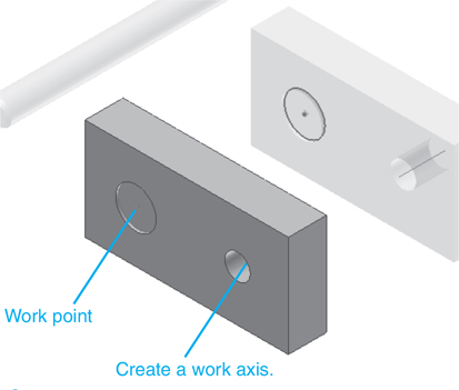
Figure 9-54
![]() Create an XY work plane aligned with the work point.
Create an XY work plane aligned with the work point.
![]() Create a work axis perpendicular to the work plane through the work point.
Create a work axis perpendicular to the work plane through the work point.
See Figure 9-55.

Figure 9-55
![]() Right-click the mouse and select Finish Edit.
Right-click the mouse and select Finish Edit.
Exercise 9-11 Adding a Work Axis to the Springs
![]() In the browser box, click the Compression Spring heading, and click the WorkAxis1 heading.
In the browser box, click the Compression Spring heading, and click the WorkAxis1 heading.
See Figure 9-56.

Figure 9-56
![]() Right-click on WorkAxis1 and select the Visibility option.
Right-click on WorkAxis1 and select the Visibility option.
The work axis will appear on the spring. See Figure 9-57.

Figure 9-57
![]() Repeat the procedure for the second spring.
Repeat the procedure for the second spring.
Exercise 9-12 Assembling the Components
![]() Insert the Post into the Front Block.
Insert the Post into the Front Block.
See Figure 9-58. If the front surface of the Front Block is used, offset the post −0.75 so that it aligns with the back surface of the Front Block.

Figure 9-58
![]() Rotate one of the springs so that the ground end is accessible. Click the Constrain tool on the Position panel under the Assemble tab and select the Mate option, and align the spring’s ground surface with the front surface of the Front Block.
Rotate one of the springs so that the ground end is accessible. Click the Constrain tool on the Position panel under the Assemble tab and select the Mate option, and align the spring’s ground surface with the front surface of the Front Block.
See Figure 9-59.

Figure 9-59
![]() Use the Mate constraint to align the spring’s work axis with the work axis through the through hole.
Use the Mate constraint to align the spring’s work axis with the work axis through the through hole.
See Figure 9-60.

Figure 9-60
![]() Repeat the procedure to position the second spring.
Repeat the procedure to position the second spring.
See Figure 9-61.

Figure 9-61
![]() Add the Rear Block to the assembly.
Add the Rear Block to the assembly.
See Figure 9-62.

Figure 9-62
Chapter Summary
This chapter showed how to draw four types of springs—compression, extension, torsion, and Belleville—using both the Coil and the Spring tools. Coil features such as natural ends and flat ends with different transition and flat angles were illustrated.
Chapter Test Questions
Multiple Choice
Circle the correct answer.
1. A compression spring is one in which the forces
a. Twist the spring
b. Pull the spring apart lengthwise
c. Push the spring together lengthwise
2. An extension spring is one in which the forces
a. Twist the spring
b. Pull the spring apart lengthwise
c. Push the spring together lengthwise
3. A torsion spring is one in which the forces
a. Twist the spring
b. Pull the spring apart lengthwise
c. Push the spring together lengthwise
4. A compression spring is defined using the Coil tool by defining
a. An axis and a work plane
b. An axis and a profile
c. A work plane and a work axis
5. Which of the following is not a type of hook for an extension spring?
a. Full loop
b. Raised hook
c. Back loop
d. Double twisted full loop
Matching
Match the following notations with their definition for creating a spring using the tools from the Spring panel.
Column A |
Column B |
|---|---|
a. n ____________ |
1. Wire diameter |
b. D1 __________ |
2. Outer spring diameter |
c. d ____________ |
3. Number of active coils |
d. L0 ___________ |
4. Spring start ground coils |
e. z01 __________ |
5. Loose spring length |
True or False
Circle the correct answer.
1. True or False: Springs can be drawn using either the Coil tool or the tools on the Spring panel.
2. True or False: The ends of compression springs are often ground flat.
3. True or False: Extension springs have hooked ends.
4. True or False: Belleville springs have coils.
5. True or False: The pitch of a spring is the distance from the center of one coil to the center of the next coil.
6. True or False: The coil direction of a spring can be either left or right.
Chapter Projects
Project 9-1: Inches
Draw the following springs using the Coil tool.
Mean Diameter = 2.00
Wire Diameter = 0.125
Pitch = 0.375
Revolution = 16
Ends = Natural
Draw a second spring from the same data that has ground ends and a preloaded length of 5.00.
See Figure P9-1.

Figure P9-1
Project 9-2: Inches
Draw the following springs using the Coil tool.
Mean Diameter = 0.50
Wire Diameter = 0.06
Pitch = 0.12
Revolution = 10
Ends = Flat, Transition angle = 90°, Flat angle = 0°
Draw a second spring from the same data that has ground ends and a preloaded length of 1.00.
See Figure P9-2.

Figure P9-2
Project 9-3: Millimeters
Draw the following springs using the Coil tool.
Mean Diameter = 8
Wire Diameter = 3
Pitch = 4
Revolution = 20
Ends = Natural
Draw a second spring from the same data that has ground ends and a preloaded length of 65.00.
See Figure P9-3.

Figure P9-3
Project 9-4: Millimeters
Draw the following springs using the Coil tool.
Mean Diameter = 24
Wire Diameter = 12
Pitch = 14
Revolution = 6
Ends = Flat, Transition Angle = 90°, Flat Angle = 45°
Draw a second spring from the same data that has ground ends and a preloaded length of 75.00.
See Figure P9-4.

Figure P9-4
Project 9-5: Millimeters
Draw the following springs using the Coil tool.
Mean Diameter = 25
Wire = 5 × 5 square
Pitch = 6
Revolution = 8
Ends = Natural
Draw the following compression springs using the tools on the Spring panel.
See Figure P9-5.

Figure P9-5
Project 9-6: Inches
Wire Diameter = 0.072
Outside Diameter = 0.625
Loose Spring Length = 3.15
Min. Load Length = 3.00
Working Stroke = 0.15
Max. Load Length = 2.95
Coil Direction = right
Active Coils = 16
Both coils
Closed End Coils = 1.5
Transition Coils = 1.0
Ground Coils = 0.75
See Figure P9-6.

Figure P9-6
Project 9-7: Inches
Wire Diameter = 0.2437
Outside Diameter = 1.250
Loose Spring Length = 4.1
Min. Load Length = 3.825
Working Stroke = 0.20
Max. Load Length = 3.82
Coil Direction = left
Active Coils = 9
Both coils
Closed End Coils = 1.5
Transition Coils = 1.0
Ground Coils = 0.75
See Figure P9-7.

Figure P9-7
Project 9-8: Millimeters
Wire Diameter = 3.00
Outside Diameter = 20.0
Loose Spring Length = 81.0
Min. Load Length = 80.0
Working Stroke = 4.0
Max. Load Length = 80.0
Coil Direction = right
Active Coils = 10
Both coils
End Coils = 1.5
Transition Coils = 1.0
Ground Coils = 0.75
See Figure P9-8.

Figure P9-8
Project 9-9: Millimeters
Wire Diameter = 5.0
Outer Diameter = 30.0
Loose Spring Length = 101.0
Min. Load Length = 100.0
Working Stroke = 6.0
Working Load Length = 94.0
Coil Direction = right
Active Coils = 9
Both coils
End Coils = 1.5
Transition Coils = 1.0
Ground Coils = 0.75
Draw the following extension springs using the tools on the Spring panel.
Note: L0 < Lc < L8. The Custom Length of the spring must be greater than the Loose Spring Length and less than the Max. Load Length.
See Figure P9-9.

Figure P9-9
Project 9-10: Inches
Spring Prestress = With Prestress
Coil Direction = right
Wire Diameter = 0.0938
Outer Diameter = 1.000
Min. Load Length = 6.00
Active Coils Number = 12
Both hooks
Spring Hook = Half Hook
Spring Hook Height = 0.50
Working Stroke = 0.25
Working Load Length = 6.1
See Figure P9-10.

Figure P9-10
Project 9-11: Inches
Spring Prestress = With Prestress
Coil Direction = right
Wire Diameter = 0.1000
Outer Diameter = 1.500
Loose Spring Length = 6.00
Active Coils Number = 16
Both hooks
Spring Hook = Non-specified Hook Type
Max. Load Length = 6.25
Working Stroke = 0.300
Working Load Length = 6.00
See Figure P9-11.

Figure P9-11
Project 9-12: Millimeters
Spring Prestress = Without Prestress
Coil Direction = right
Wire Diameter = 4
Outer Diameter = 22
Loose Spring Length = 130
Active Coils Number = 8
Both hooks
Spring Hook = Raised Hook
Hook Length = 16.936
Max. Load Spring Length = 138
Working Stroke = 4
Working Load Length = 136
See Figure P9-12.

Figure P9-12
Project 9-13: Millimeters
Draw the following extension springs using the Coil tool.
Spring Prestress = With Prestress
Coil Direction = right
Wire Diameter = 3.75
Outer Diameter = 40
Loose Spring Length = 64.923
Active Coils Number = 4.18
Both hooks
Spring Hook = Half Hook
Hook Length = 22.514
Max. Load Spring Length = 80
Working Stroke = 6
Working Load Length = 74
See Figure P9-13.

Figure P9-13
Project 9-14: Inches
Wire Diameter = 0.19
Mean Diameter = 1.00
Pitch = .375
Revolution = 12
Taper = 0
Start Coil End = Flat, Transition Angle = 90.0°, Flat Angle = 90.0°
End Coil End = Flat, Transition Angle = 0.0°, Flat Angle = 0.0°
Extension Distance = 0.50
Arc Radius = 1.00
See Figure P9-14.

Figure P9-14
Project 9-15: Inches
Wire Diameter = 0.375
Mean Diameter = 1.50
Pitch = .625
Revolution = 24
Taper = 0
Start Coil End = Flat, Transition Angle = 90.0°, Flat Angle = 90.0°
End Coil End = Flat, Transition Angle = 0.0°, Flat Angle = 0.0°
Extension Distance = 1.50
Arc Radius = 1.50
See Figure P9-15.

Figure P9-15
Project 9-16: Millimeters
Wire Diameter = 16
Mean Diameter = 30
Pitch = 30
Revolution = 10
Taper = 0
Start Coil End = Flat, Transition Angle = 90.0°, Flat Angle = 90.0°
End Coil End = Flat, Transition Angle = 0.0°, Flat Angle = 0.0°
Extension Distance = 18
Arc Radius = 30
See Figure P9-16.

Figure P9-16
Project 9-17: Millimeters
Draw the following extension springs using the Coil tool.
Wire Diameter = 8
Mean Diameter = 24
Pitch = 14
Revolution = 16
Taper = 0
Start Coil End = Flat, Transition Angle = 90.0°, Flat Angle = 90.0°
End Coil End = Flat, Transition Angle = 0.0°, Flat Angle = 0.0°
Extension Distance = 26
Arc Radius = 24
Draw the following torsion springs using the tools on the Spring panel. Use the default values for any values not specified.
See Figure P9-17.

Figure P9-17
Project 9-18: Inches
Coil Direction = right
Straight torsion arms
A Load Coils the Spring
Wire Diameter = 0.1055
Outside Diameter = 0.875
Start Arm Length = 1.50
End Arm Length = 0.75
Active Coils Number = 12
Min. Angular Deflection of Working Arm = 12
Angle of Working Stroke = 36
Angular Deflection of Working Arm = 15
See Figure P9-18.

Figure P9-18
Project 9-19: Inches
Coil Direction = right
Straight torsion arms
A Load Uncoils the Spring
Wire Diameter = 0.072
Outside Diameter = 0.500
Start Arm Length = 0.50
End Arm Length = 0.50
Active Coils Number = 18
Min. Angular Deflection of Working Arm = 20
Angle of Working Stroke = 10
Angular Deflection of Working Arm = 30
See Figure P9-19.

Figure P9-19
Project 9-20: Millimeters
Coil Direction = left
Straight torsion arms
A Load Coils the Spring
Wire Diameter = 2.00
Outside Diameter = 16
Arm of Working Force = 20.0
Arm of Support = 20.0
Active Coils Number = 10
Min. Angular Deflection of Working Arm = 10
Angle of Working Stroke = 40
Angular Deflection of Working Arm = 10
See Figure P9-20.

Figure P9-20
Project 9-21: Millimeters
Draw the following torsion springs using the Coil tool.
Coil Direction = right
Straight torsion arms
A Load Uncoils the Spring
Wire Diameter = 3.0
Mean Diameter = 40
Arm of Working Force = 35
Arm of Support = 30
Active Coils Number = 20
Min. Angular Deflection of Working Arm = 15
Angle of Working Stroke = 50
Angular Deflection of Working Arm = 15
See Figure P9-21.

Figure P9-21
Project 9-22: Inches
Create a drawing using the Standard (in).ipt format.
Wire Diameter = 0.19
Mean Diameter = 1.25
Pitch = 0.375
Revolution = 12
Start Coil = Flat, Transition Angle = 90°, Flat Angle = 90°
End Coil = Flat, Transition Angle = 45°, Flat Angle = 45°
Arm Length (both arms) = 2.00
See Figure P9-22.

Figure P9-22
Project 9-23: Inches
Create a drawing using the Standard (in).ipt format.
Wire Diameter = 0.06
Mean Diameter = 0.50
Pitch = 0.125
Revolution = 20
Start Coil = Flat, Transition Angle = 90°, Flat Angle = 90°
End Coil = Flat, Transition Angle = 45°, Flat Angle = 45°
Arm Length (both arms) = 1.00
See Figure P9-23.

Figure P9-23
Project 9-24: Millimeters
Create a drawing using the Standard (mm).ipt format.
Wire Diameter = 4.0
Mean Diameter = 12.0
Pitch = 6
Revolution = 18
Start Coil = Flat, Transition Angle = 90°, Flat Angle = 90°
End Coil = Flat, Transition Angle = 45°, Flat Angle = 45°
Arm Length (both arms) = 15
See Figure P9-24.

Figure P9-24
Project 9-25: Millimeters
Create a drawing using the Standard (mm).ipt format.
Wire Diameter = 5
Mean Diameter = 40.0
Pitch = 10
Revolution = 18
Start Coil = Flat, Transition Angle = 90°, Flat Angle = 90°
End Coil = Flat, Transition Angle = 45°, Flat Angle = 45°
Arm Length (both arms) = 60
See Figure P9-25.

Figure P9-25
Project 9-26: Inches
Draw the Damper Assembly shown in Figure P9-26. This exercise is loosely based on a damper system placed under the seat of helicopter pilots to help minimize the amount of vibration they experience.


Figure P9-26
Spring data:
Spring Strength Calculation = Work Forces Calculation
Wire Diameter = 0.125
Outside Diameter = 1.000
Min. Load Length = 2.10
Working Stroke = 0.25
Working Load Length = 2.00
Both coils
Closed End Coils = 1.50
Transition Coils = 1.00
Ground Coils = 0.75
Active Coils = 10
Draw the following:
An assembly drawing
A presentation drawing
An exploded isometric drawing
A parts list
Project 9-27: Millimeters
Draw the Circular Damper Assembly shown in Figure P9-27.


Figure P9-27
The Threaded Post is M18 × 530 mm.
Spring data:
Wire Diameter = 3.0
Outer Diameter = 28
Loose Spring Length = 81
Min. Load Length = 80
Working Stroke = 5
Working Load Length = 78
Coil Direction = right
Closed End Coils = 1.5
Transition Coils = 1.00
Ground Coils = 0.75
Active Coils = 16
Draw the following:
A. An assembly drawing
B. A presentation drawing
C. An exploded isometric drawing
D. A parts list