Learn how to dimension different shapes and features
Begin 3D dimensioning
Introduction
Inventor uses two types of dimensions: model and drawing. Model dimensions are created as the model is being constructed and may be edited to change the shape of a model. Drawing dimensions can be edited, but the changes will not change the shape of the model. If the shape of a model is changed, the drawing dimensions associated with the revised surfaces will change to reflect the new values.
A dimension attached to a specified distance on a drawing that can be edited without changing the shape of the model.
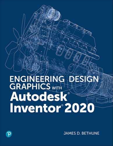
Dimensions are usually applied to a drawing using either American National Standards Institute (ANSI) or International Organization for Standardization (ISO) standards. If English units are selected when a new drawing is started, the ANSI inch standards (ANSI (in).idw) will be invoked. If metric units are selected, the ISO standards (ISO.idw) may be invoked. This text uses ANSI standards for both inch and metric units. Metric units will use the ANSI-Metric standards.
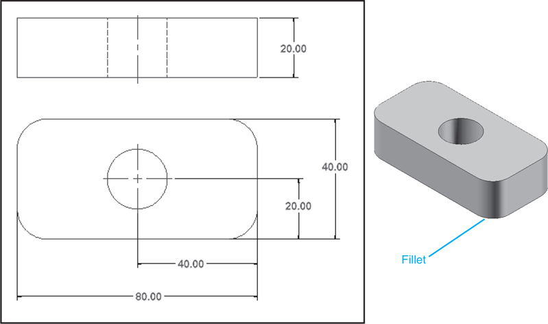
Figure 7-1 shows a drawing that includes only the drawing dimensions. The Metric option was selected before the model was drawn. The model dimensions were created automatically as the model was created. The Dimension tool was used to edit the sketch dimensions.
Figure 7-1
Terminology and Conventions—ANSI
Some Common Terms
Figure 7-2 shows both ANSI and ISO style dimensions. The terms apply to both styles.
Figure 7-2
Dimension Lines: In mechanical drawings, lines between extension lines that end with an arrowhead and include a numerical dimensional value located within the line.
Extension Lines: Lines that extend away from an object and allow dimensions to be located off the surface of an object.
Leader Lines: Lines drawn at an angle, not horizontal or vertical, that are used to dimension specific shapes such as holes. The start point of a leader line includes an arrowhead. Numerical values are drawn at the end opposite the arrowhead.
Linear Dimensions: Dimensions that define the straight-line distance between two points.
Angular Dimensions: Dimensions that define the angular value, measured in degrees, between two straight lines.
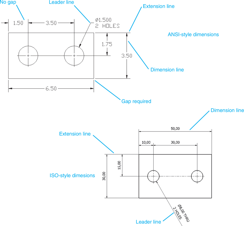
Dimension lines should be drawn evenly spaced; that is, the distance between dimension lines should be uniform. A general rule of thumb is to locate dimension lines about ½ in. or 15 mm apart.
There should a noticeable gap between the edge of a part and the beginning of an extension line. This serves as a visual break between the object and the extension line. The visual difference between the line types can be enhanced by using different colors for the two types of lines.
Leader lines are used to define the size of holes and should be positioned so that the arrowhead points toward the center of the hole.
Centerlines may be used as extension lines. No gap is used when a centerline is extended beyond the edge lines of an object.
Align dimension lines whenever possible to give the drawing a neat, organized appearance.
Avoid crossing extension lines. Place longer dimensions farther away from the object than shorter dimensions.
Do not locate dimensions within cutouts; always use extension lines.
Do not locate any dimension close to the object. Dimension lines should be at least 1/2 in. or 15 mm from the edge of the object.
Avoid long extension lines. Locate dimensions in the same general area as the feature being defined.
Creating Drawing Dimensions
Drawing dimensions are added to a drawing using the Dimension tool. The Dimension tool is located on the Dimension panel under the Annotate tab.
This section will add drawing dimensions to the model view shown in Figure 7-5. The dimensions will be in compliance with ANSI Metric standards. The model was drawn using the Standard (mm).ipt format. All values are in millimeters.
Figure 7-5
A dimensioned view of the model used in this example is available in Figure 7-11. The holes have a diameter of 10. Use the Standard (mm).ipt format and create a solid model. Extrude the model to a thickness of 10. Save the model as BLOCK, 2 HOLES.
Drawing dimensions are different from model dimensions. Model dimensions are created as the model is created and can be used to edit (change the shape of) the model. Drawing dimensions are attached to a specified distance. Changing a drawing dimension will not change the shape of the model.
Tip
Changing the scale of a drawing will change the size of the drawing. The size of the dimension text will not change.
Exercise 7-1Creating an Orthographic View for Dimensioning
Click on the New tool, then the Metric tab. Select the ANSI (mm).idw format, the Drawing – Create an Annotated Document, and click OK.
Select the Base tool from the Create panel under the Place Views tab.
The Drawing View dialog box will appear.
Select the Open an existing file box, select the BLOCK, 2 HOLES file, click Open, locate the view on the drawing screen, and click the mouse.
If needed, change the scale of the drawing.
Click OK.
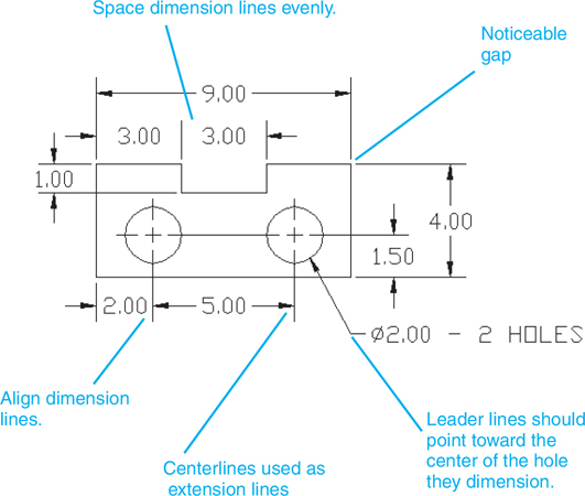
Exercise 7-2Accessing the Annotate panel
Click the Annotate tab.
The panel bar will change to the Annotate panel bar shown in Figure 7-6. The Dimension tool is the first tool listed.
Figure 7-6
Adding Centerlines to Holes
The tools for adding centerlines to a drawing are located on the Symbols panel under the Annotate tab. See Figure 7-7.
Figure 7-7
Figure 7-8 shows a front orthographic view of the model to be dimensioned. Centerlines were added to the model using the Center Mark tool located on the Symbols panel.
Figure 7-8
Click the Center Mark tool.
Click the edge of the circles.
Center marks will appear on the holes.
Right-click the mouse and click the OK option.
Move the cursor over the horizontal centerline of the left circle. Green circles will appear.
Click and drag the horizontal centerline so that it intersects the horizontal centerline of the right circle.
See Figure 7-9. This common centerline will be used to indicate that the holes are horizontally aligned.
Figure 7-9
Exercise 7-3Adding Horizontal Dimensions
Click the Dimension tool.
Move the cursor into the drawing area and first click the upper left corner of the model.
A green circle will appear on the corner, indicating that it has been selected.
Click the top end of the left hole’s vertical centerline.
Move the cursor, locating the dimension (15), then press the left mouse button.
The Edit Dimension dialog box will appear; click OK.
Still using the Dimension tool, click the top end of the two vertical centerlines and locate a second horizontal dimension between the two vertical hole centerlines (20).
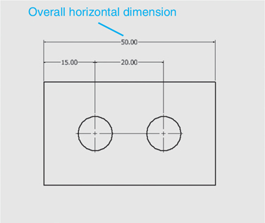
Overall dimensions define the outside sizes of a model, the maximum length, width, and height. It is important that overall dimensions be easy to find and read, as they are often used to determine the stock sizes needed to produce the model.
Dimensions that define the outside sizes of a model: the maximum length, width, and height.
Convention calls for overall dimensions to be located farther away from the model than any other dimensions. In Figure 7-10, the 50 overall dimension was located above the other two horizontal dimensions—that is, farther away from the model. The dimension could also have been located below the model.
Note that the spacing between the model’s edge and the two horizontal dimensions is approximately equal to the distance between the overall dimension and the two horizontal dimensions.
Vertical Dimensions
ANSI standards call for the text of vertical dimensions to be written unidirectionally. This means that the text should be written horizontally and be read from left to right. Figure 7-11 shows two vertical dimensions added to the model. Both use unidirectional text. Note also that the overall height dimension is located the farthest away from the model’s edge.
Figure 7-11
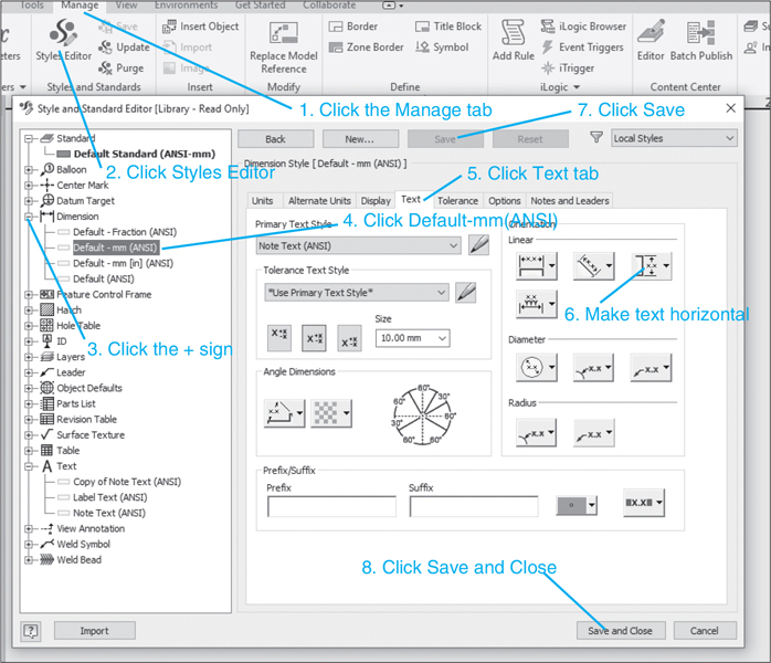
Exercise 7-4Creating Unidirectional Text
Click the Manage tab at the top of the screen, and select the Styles Editor tool located on the Styles and Standards panel.
The Style and Standard Editor dialog box will appear. See Figure 7-12.
Figure 7-12
Click the + sign to the left of the Dimension listing.
Select the Default - mm (ANSI) option.
The Style and Standard Editor dialog box will change.
Select the Text tab under the Dimension Style heading.
Go to the Orientation box and select the Vertical Dimension: Inline - Horizontal option as shown.
Click the Save box, then click Save and Close.
All vertical dimensions will now be written using unidirectional text.
Use the Dimension tool and add the vertical dimensions to the block. The vertical dimensions, 15.00 and 30.00, should be unidirectional as shown.
Positioning Dimension Text
You can control the location of dimension text by the sequence used to define the distance to be dimensioned. See Figure 7-13. The text will appear on the side of the first selected edge or point. For example, the text appears on the left when the left vertical line is selected first, and on the right when the right vertical line is selected first.
Figure 7-13
Dimensioning Holes
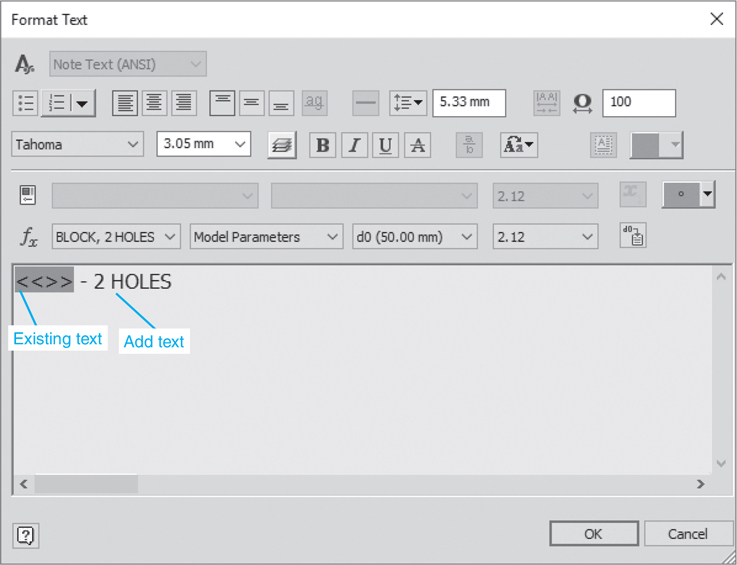
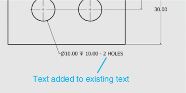
There are two Ø10 holes in the BLOCK, 2 HOLES model. Two hole dimensions could be applied, or one dimension could be used with the additional note Ø10 - 2 HOLES. In general, it is desirable to use as few dimensions as possible to define the model’s size clearly and completely. This helps prevent a cluttered and confusing drawing.
Click the Hole and Thread tool on the Feature Notes panel under the Annotate tab, then the edge of one of the holes.
Drag the dimension away from the model.
Locate the hole dimension and left-click the mouse.
The Styles Editor can also be used to change the height of the text.
Tip
Drawing convention calls for all drawing text to use uppercase letters.
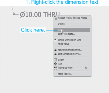
Exercise 7-6Editing a Hole Dimension
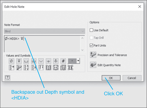
The hole dimension shown in Figure 7-17 includes the depth symbol and 10.00 after the dimension value. Including the depth symbol after a hole dimension is an optional practice, and not all companies include it. If a hole has no note after it, it is assumed to go all the way through. The word may be removed using the Edit Hole Note option.
Move the cursor to the hole dimension and right-click the mouse.
Select the Edit Hole Note option.
The Edit Hole Note dialog box will appear. See Figure 7-18.
Figure 7-18
Backspace out the depth symbol and <HDIA>.
Click the OK box.
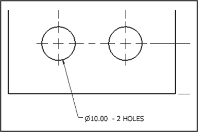
Figure 7-19 shows the resulting hole dimension. If the 2 HOLES note is not added using the Text option, it can be added using the Edit Hole Note option.
Figure 7-19
Drawing Scale
Drawings are often drawn “to scale” because the actual part is either too big to fit on a sheet of drawing paper or too small to be seen. For example, a microchip circuit must be drawn at several thousand times its actual size to be seen.
Drawing scales are written using the following formats:
SCALE: 1 = 1
SCALE: FULL
SCALE: 1000 = 1
SCALE: .25 = 1
In each example, the value on the left indicates the scale factor. A value greater than 1 indicates that the drawing is larger than actual size. A value smaller than 1 indicates that the drawing is smaller than actual size.
Regardless of the drawing scale selected the dimension values must be true size. Figure 7-20 shows the same rectangle drawn at two different scales. The top rectangle is drawn at a scale of 1 = 1, or its true size. The bottom rectangle is drawn at a scale of 2 = 1, or twice its true size. In both examples, the 3.00 dimension remains the same.
Figure 7-20
Units
It is important to understand that dimensional values are not the same as mathematical units. Dimensional values are manufacturing instructions and always include a tolerance, even if the tolerance value is not stated. Manufacturers use a predefined set of standard dimensions that are applied to any dimensional value that does not include a written tolerance. Standard tolerance values differ from organization to organization. Figure 7-21 shows a chart of standard tolerances.
Figure 7-21
In Figure 7-22 a distance is dimensioned twice: once as 5.50 and a second time as 5.5000. Mathematically, these two values are equal, but they are not the same manufacturing instruction. The 5.50 value could, for example, have a standard tolerance of ±.01, whereas the 5.5000 value could have a standard tolerance of ±.0005. A tolerance of ±.0005 is more difficult and, therefore, more expensive to manufacture than a tolerance of ±.01.
Figure 7-22
Figure 7-23 shows examples of units expressed in millimeters and in decimal inches. A zero is not required to the left of the decimal point for decimal inch values less than one. Whole-number millimeter values do not require zeros to the right of the decimal point unless needed to specify a tolerance. Millimeter and decimal inch values never include symbols; the units will be defined in the title block of the drawing.
Figure 7-23
Exercise 7-7Preventing a 0 from Appearing to the Left of the Decimal Point
While still in the ANSI (mm).idw format, click the Manage tab at the top of the screen, then select the Style and Standard Editor option. See Figure 7-24.
The Style and Standard Editor dialog box will appear.
Figure 7-24
Click the + sign to the left of Dimension, and select Default - mm (ANSI).
Select the Units tab.
Remove the check mark from the Leading Zero box in the Display area.
This procedure creates a new dimension style that suppresses all leading zeros.
Click the Save and Close box. The Default - mm (ANSI) standard may already have the leading zero suppressed.
Exercise 7-8Changing the Number of Decimal Places in a Dimension Value
Click on the Manage tab at the top of the screen, then select the Style and Standard Editor option.
The Style and Standard Editor dialog box will appear. See Figure 7-25.
Figure 7-25
Click the + sign to the left of Dimension, and select Default - mm (ANSI).
Select the Units tab.
Click the scroll arrow on the right side of the Precision box.
A listing of available precision settings will cascade down.
Select the desired precision value.
In this example, 2 decimal places was selected.
Click the Save and Close box.
Aligned Dimensions
Aligned dimensions are dimensions that are parallel to a slanted edge or surface. They are not horizontal or vertical. The unit values for aligned dimensions should be horizontal or unidirectional.
Exercise 7-9Creating an Aligned Dimension
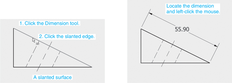
Figure 7-26 shows an orthographic view of a model that includes a slanted surface. The model was created using the Standard (mm).ipt format, and the orthographic view was created using the ANSI (mm).idw format. The Dimension tool was used to add the aligned dimension.
Figure 7-26
Click the Annotate tab.
Click the Dimension tool, located on the Dimension panel, then move the cursor onto the slanted edge to be dimensioned.
The edge will change color, indicating that it has been selected.
Left-click the mouse.
Move the mouse as necessary to locate the aligned dimension.
If an aligned dimension is not created, right-click the mouse and select Dimension Type, Aligned before locating the dimension.
Exercise 7-10Creating a Unidirectional Aligned Dimension
Aligned dimensions can be made unidirectional by using the Orientation option on the Style and Standard Editor dialog box.
Click on the Manage tab at the top of the screen, then select the Style and Standard Editor tool.
The Style and Standard Editor dialog box will appear. See Figure 7-27.
Figure 7-27
Click the + sign to the left of the Dimension listing.
Select Default - mm (ANSI).
The Style and Standard Editor dialog box will change.
Select the Text tab.
Go to the Orientation box and select the Align Dimension: Inline - Horizontal option as shown.
Click the Save and Close box.
The aligned text will become unidirectional.
Radius and Diameter Dimensions
Figure 7-28 shows an object that includes both fillets and circles. The object is 10 mm thick. The general rule is to dimension arcs using a radius dimension, and circles using diameter dimensions. This convention is consistent with the tooling required to produce the feature shape. Any arc greater than 180° is considered a circle and is dimensioned using a diameter. In this example, the hole was omitted. The horizontal and vertical dimensions were added.
Figure 7-28
Exercise 7-11Creating a Radius Dimension
Click the Leader Text tool located on the Text panel under the Annotate tab.
Click one of the filleted corners and move the cursor away from the corner.
Create a short horizontal segment on the leader line.
Right-click the mouse and select the Continue option.
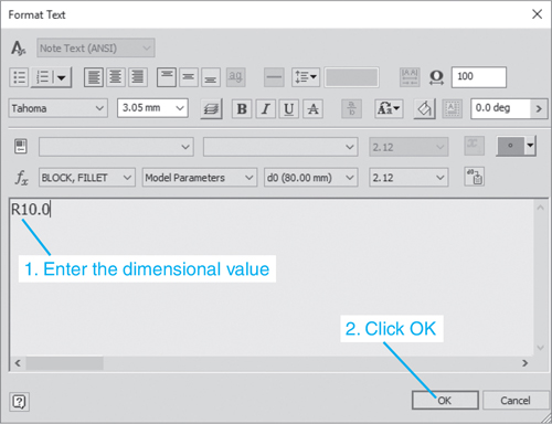
The Format Text dialog box will appear. See Figure 7-30.
Figure 7-30
Enter R10.00, and click OK.
Press the <Esc> key to end the dimensioning sequence.
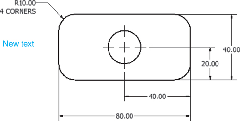
Figure 7-31 shows the resulting dimension. There are four equal arcs on the object, and they all must be dimensioned. It would be better to add the words 4 CORNERS to the radius dimension than to include four radius dimensions.
Figure 7-31
Exercise 7-12Adding Text to an Existing Drawing Dimension
Move the cursor to the fillet dimension.
Filled colored circles will appear, indicating that the dimension has been selected.
Right-click the mouse and select the Edit Leader Text option.
The Format Text dialog box will appear with the existing text. See Figure 7-32.
Figure 7-32
Type 4 CORNERS under the existing text and click the OK box.
Holes are dimensioned by stating their diameter and depth, if any. Holes that go completely through an object are defined using only a diameter dimension. See Figure 7-34. The word THRU may be added if desired.
Figure 7-34
Exercise 7-13Dimensioning a Through Hole
Click the Hole and Thread Notes tool on the Feature Notes panel under the Annotate tab.
Click the edge of the hole and move the cursor away from the hole, off the surface of the part.
Locate and enter the dimension by checking the left mouse button.
Right-click the mouse and select the OK option.
Move the cursor over the hole dimension, right-click the mouse, and select the Edit Hole Note option.
Backspace out the depth symbol and value, then click OK.
Tip
The Dimension tool may also be used.
Dimensioning Individual Holes
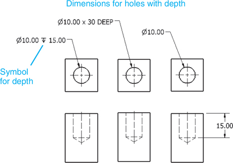
Figure 7-35 shows three different methods that can be used to dimension a hole that does not go completely through an object. Dimension the hole using the Dimension tool. The depth value will be included automatically. The symbol indicates depth.
Figure 7-35
Figure 7-36 shows three methods of dimensioning holes in section views. The single-line-note version is the preferred method.
Figure 7-36
Sample Problem SP7-1
Figure 7-37 shows orthographic views of a model that includes two holes that do not pass through the model. The dimensions other than the dimensions for the holes are applied using the Dimension tool located under the Annotate tab.
Figure 7-37
To dimension the holes:
Click the Hole and Thread Notes tool on the Feature Notes panel under the Annotate tab.
Click the edge of the left hole and move the cursor away from the hole.
Locate a position for the hole’s dimension and click the left mouse button.
Right-click the mouse and select the OK option.
Repeat the same procedure for the right hole.
Remember that a hole’s depth dimension does not include the conical point at the bottom of the hole.
See Figure 7-38. Note that the depth symbol is used automatically. The symbol can be edited if desired.
Figure 7-38
Dimensioning Hole Patterns
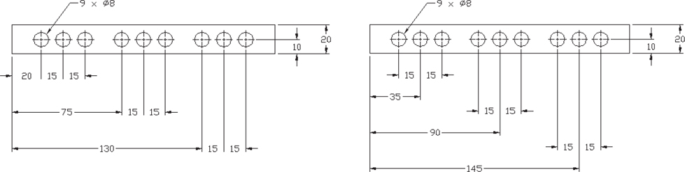
Figure 7-39 shows two different hole patterns dimensioned. The circular pattern includes the note Ø10 - 4 HOLES. This note serves to define all four holes within the object.
Figure 7-39
Figure 7-39 also shows a rectangular object that contains five holes of equal diameter, equally spaced from one another. The notation 5 ×Ø10 specifies 5 holes of 10 diameter. The notation 4 ×20 (=80) means 4 equal spaces of 20. The notation (=80) is a reference dimension and is included for convenience. Reference dimensions are explained in Chapter 8.
Figure 7-40 shows two additional methods for dimensioning repeating hole patterns. Figure 7-41 shows a circular hole pattern that includes two different hole diameters. The hole diameters are not noticeably different and could be confused. One group is defined by indicating letter (A); the other is dimensioned in a normal manner.
Figure 7-40
Figure 7-41
Using Symbols with Dimensions
In an attempt to eliminate language restrictions from drawings, ANSI standards permit the use of certain symbols for dimensions. Like musical notation that can be universally read by people who speak different languages, symbolic dimensions can be read by different people regardless of which language they speak. For example, the symbol Ø replaces the notation DIA.
Figure 7-42 shows a Ø10 hole that has a depth of 15. Inventor will automatically apply symbolic dimensions. The shown dimension is created as follows.
Figure 7-42
Access the Hole and Thread Notes tool under the Annotate tab.
Click the edge of the circular view of the hole.
Move the cursor away from the hole’s edge and locate the dimension.
Right-click the mouse and select the OK option.
Exercise 7-14Adding Symbols to Existing Dimension Text
Figure 7-43 shows an object with a Ø20.00 dimension. Add a depth requirement of 5.00.
Figure 7-43
Right-click the dimension and select the Edit... option.
The Edit Dimension dialog box will appear. See Figure 7-44.
Figure 7-44
Click the depth symbol.
The depth symbol will appear next to the existing dimension in the Note Format box.
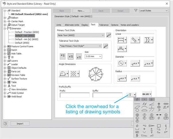
Drawing symbols can also be accessed using the Style and Standard Editor option. Click the Manage tab at the top of the screen, click the Styles Editor option, click Dimension, click Default - mm (ANSI), click the Text tab, and click the Insert Symbol box in the lower right corner of the dialog box. See Figure 7-46.
Figure 7-46
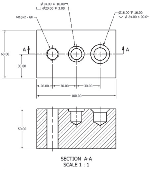
Dimensioning Counterbored, Countersunk Holes
Chapter 6 explained how to draw counterbored and countersunk holes. This section shows how to dimension countersunk and counterbored holes.
Figure 7-48 shows a 70 × 30 × 20 block that includes both a counterbored and a countersunk hole. The holes are located 20 mm from the ends of the block, 30 mm apart. The sizes for the holes were determined based on the fastener information given in Chapter 6. The Hole dialog boxes used to create the holes are also shown. Use the given information in Figure 7-47 to create the two holes.
Figure 7-47
Figure 7-48
The information used to create the holes will automatically be used to create the hole’s dimension. Prefixes and suffixes may be added to the dimensions, and the dimension value may be changed using the Edit Hole Note option. Hole dimension values may also be changed by editing the hole’s feature value on the original model.
Exercise 7-15Dimensioning a Counterbored Hole
The counterbored hole has a clear hole that goes completely through the block.
Click the Annotate tab and click the Hole and Thread tool.
Click the edge of the circular view of the hole.
Move the cursor away from the hole’s edge and locate the dimension.
Right-click the mouse and select the OK option.
Note how the dimensions match exactly the values used to create the hole. See Figures 7-47 and 7-48.
Exercise 7-16Dimensioning a Countersunk Hole
The countersunk hole has M8 threads and a thread depth of 10 mm.
Create an orthographic view of the model using the ANSI (mm).idw format.
Add centerlines.
Click the Annotate tab and click the Hole and Thread Notes tool.
Click the edge of the circular view of the hole.
Move the cursor away from the hole’s edge and locate the dimension.
Right-click the mouse and select the OK option.
Note how the dimensions match exactly the values used to create the hole.
Angular Dimensions
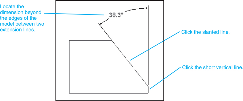
Figure 7-49 shows a model that includes a slanted surface. The dimension value is located beyond the model between two extension lines. Locating dimensions between extension lines is preferred to locating the value between an extension line and the edge of the model.
Figure 7-49
Exercise 7-17Creating an Angular Dimension
Create an orthographic view of the model using the ANSI (mm).idw format.
Click the Annotate tab and click the Dimension tool.
Click the slanted line, then click the short vertical line on the right side of the model.
Move the cursor away from the hole’s edge and locate the dimension.
Right-click the mouse and select the OK option.
Avoiding Overdimensioning
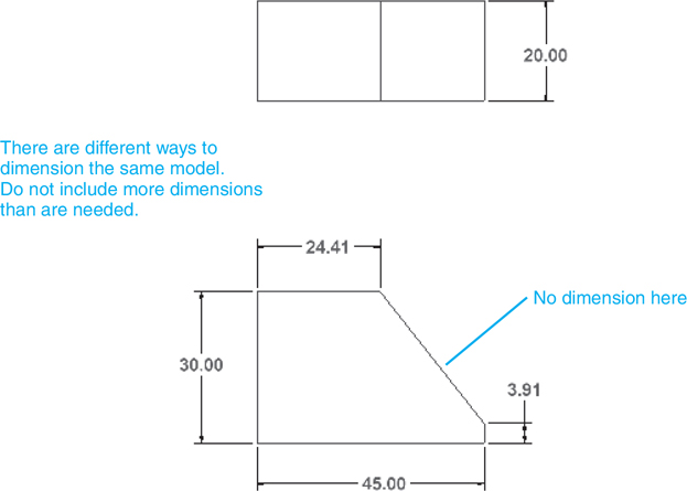
Figure 7-50 shows a shape dimensioned using an angular dimension. The shape is completely defined. Any additional dimension would be an error. It is tempting, in an effort to make sure a shape is completely defined, to add more dimensions, such as a horizontal dimension for the short horizontal edge at the top of the shape. This dimension is not needed and is considered double dimensioning.
Figure 7-50
Figure 7-51 also shows the same front view dimensioned using only linear dimensions. The choice of whether to use angular or linear dimensions depends on the function of the model and which distances are more critical.
Figure 7-51
Figure 7-52 shows an object dimensioned two different ways. The dimensions used in the top example do not include a dimension for the width of the slot. This dimension is allowed to float—that is, allowed to accept any tolerance buildup. The dimensions used in the bottom example dimension the width of the slot but not the upper right edge. In this example, the upper right edge is allowed to float or accept any tolerance buildup. The choice of which edge to float depends on the function of the part. If the slot were to interface with a tab on another part, then it would be imperative that it be dimensioned and toleranced to match the interfacing part.
Figure 7-52
Ordinate Dimensions
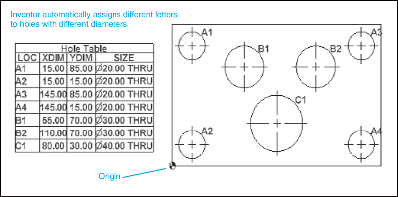
Ordinate dimensions are dimensions based on an X,Y coordinate system. Ordinate dimensions do not include extension lines, dimension lines, or arrowheads, but simply horizontal and vertical leader lines drawn directly from the features of the object. Ordinate dimensions are particularly useful when dimensioning an object that includes many small holes.
A dimension based on an X,Y coordinate system that consists simply of horizontal and vertical leader lines.
Figure 7-53 shows a model that is to be dimensioned using ordinate dimensions. Ordinate dimensions values are calculated from the X,Y origin, which, in this example, is the lower left corner of the front view of the model.
Figure 7-53
Exercise 7-18Creating Ordinate Dimensions
Create an orthographic view of the model using the ANSI (mm).idw format.
Click the Annotate tab, click on the Ordinate tool, and click the Ordinate Set tool.
Note how the extension line from the first hole’s centerline curves so that the dimension value may be located in line with the first dimension. Inventor will automatically align ordinate dimensions.
Right-click the mouse and click the Create option.
Right-click the mouse and select the Repeat Ordinate Dimension Set option.
Click the left corner so that the vertical edge is highlighted.
Move the cursor to the left, away from the corners, and right-click the mouse.
Select the Continue option.
Right-click the mouse and select the Make Origin option.
Locate the dimension and click the mouse.
Again start with the lower left corner of the model, then click the appropriate horizontal centerlines. See Figure 7-57.
Figure 7-57
Exercise 7-19Adding Hole Dimensions
Click the Hole and Thread Notes option under the Annotate tab.
Baseline dimensions are a series of dimensions that originate from a common baseline or datum line. Baseline dimensions are very useful because they help eliminate the tolerance buildup that is associated with chain-type dimensions. The Baseline Dimension tool is found on the Dimension panel under the Annotate tab. See Figure 7-59.
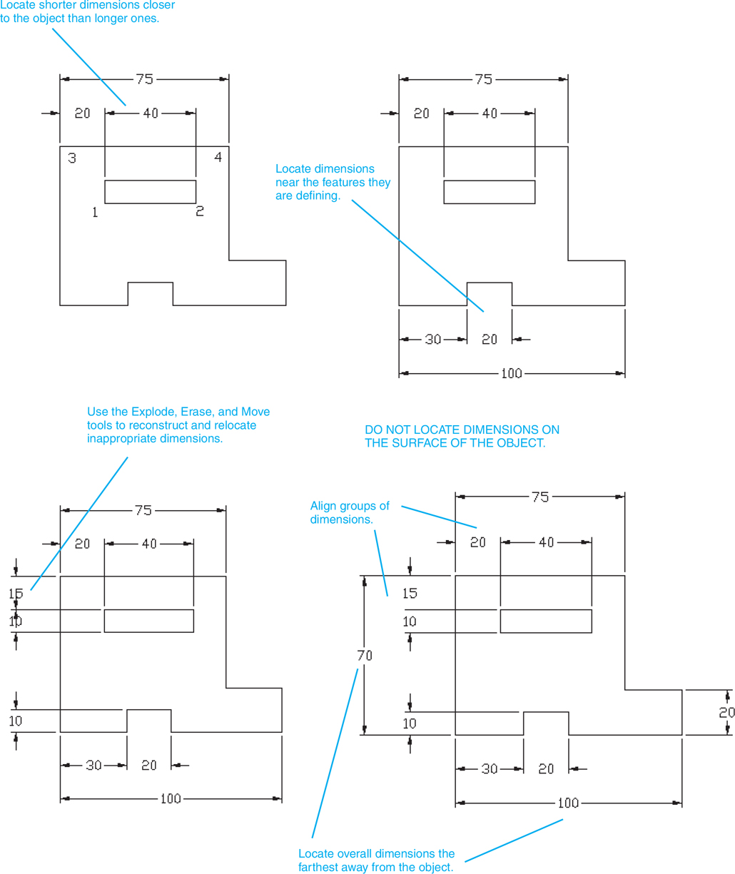
There are eight general rules concerning the location of dimensions. See Figure 7-63.
Figure 7-63
Locate dimensions near the features they are defining.
Do not locate dimensions on the surface of the object.
Align and group dimensions so that they are neat and easy to understand.
Avoid crossing extension lines.
Sometimes it is impossible not to cross extension lines because of the complex shape of the object, but whenever possible, avoid crossing extension lines.
Do not cross dimension lines.
Locate shorter dimensions closer to the object than longer ones.
Always locate overall dimensions the farthest away from the object.
Do not dimension the same distance twice. This is called double dimensioning and will be discussed in Chapter 8.
Fillets and Rounds
Fillets and rounds may be dimensioned individually or by a note. In many design situations all the fillets and rounds are the same size, so a note as shown in Figure 7-64 is used. Any fillets or rounds that have a different radius from that specified by the note are dimensioned individually.
Figure 7-64
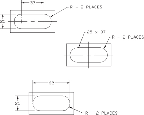
Rounded Shapes—Internal
Internal rounded shapes are called slots. Figure 7-65 shows three different methods for dimensioning slots. The end radii are indicated by the note R - 2 PLACES, but no numerical value is given. The width of the slot is dimensioned, and it is assumed that the radius of the rounded ends is exactly half of the stated width.
Figure 7-66 shows two shapes with external rounded ends. As with internal rounded shapes, the end radii are indicated but no value is given. The width of the object is given, and the radius of the rounded end is assumed to be exactly half of the stated width.
Figure 7-66
The second example shown in Figure 7-66 shows an object dimensioned using the object’s centerline. This type of dimensioning is done when the distance between the holes is more important than the overall length of the object; that is, the tolerance for the distance between the holes is more exact than the tolerance for the overall length of the object.
The overall length of the object is given as a reference dimension (100). This means the object will be manufactured based on the other dimensions, and the 100 value will be used only for reference.
Objects with partially rounded edges should be dimensioned as shown in Figure 7-66. The radii of the end features are dimensioned. The center point of the radii is implied to be on the object centerline. The overall dimension is given; it is not referenced unless specific radii values are included.
Irregular Surfaces
There are three different methods for dimensioning irregular surfaces: tabular, baseline, and baseline with oblique extension lines. Figure 7-67 shows an irregular surface dimensioned using the tabular method. An XY axis is defined using the edges of the object. Points are then defined relative to the XY axis. The points are assigned reference numbers, and the reference numbers and XY coordinate values are listed in chart form as shown.
Figure 7-67
Figure 7-68 shows an irregular curve dimensioned using baseline dimensions. The baseline method references all dimensions to specified baselines. Usually there are two baselines—one horizontal and one vertical.
Figure 7-68
It is considered poor practice to use a centerline as a baseline. Centerlines are imaginary lines that do not exist on the object and would make it more difficult to manufacture and inspect the finished objects.
Baseline dimensioning is very common because it helps eliminate tolerance buildup and is easily adaptable to many manufacturing processes. Inventor has a special Baseline Dimension tool for use in creating baseline dimensions.
Polar Dimensions
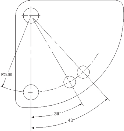
Polar dimensions are similar to polar coordinates. A location is defined by a radius (distance) and an angle. Figure 7-69 shows an object that includes polar dimensions. The holes are located on a circular centerline, and their positions from the vertical centerline are specified using angles.
Figure 7-70 shows an example of a hole pattern dimensioned using polar dimensions.
Figure 7-70
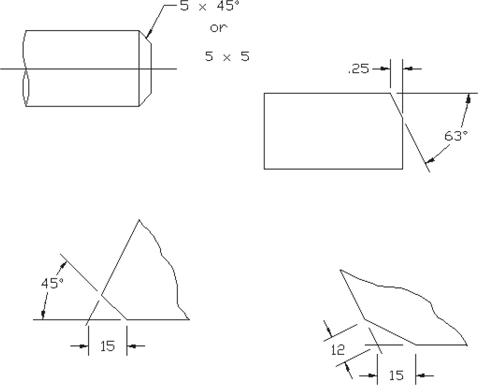
Chamfers
Chamfers are angular cuts made on the edges of objects. They are usually used to make it easier to fit two parts together. They are most often made at 45° angles but may be made at any angle. Figure 7-71 shows two objects with chamfers between surfaces 90° apart and two examples between surfaces that are not 90° apart. Either of the two types of dimensions shown for the 45° dimension may be used. If an angle other than 45° is used, the angle and setback distance must be specified.
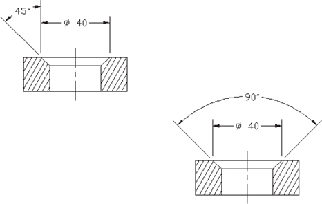
Figure 7-72 shows two examples of internal chamfers. Both define the chamfer using an angle and diameter. Internal chamfers are very similar to countersunk holes.
Figure 7-72
Knurling
There are two types of knurls: diamond and straight. Knurls are used to make it easier to grip a shaft, or to roughen a surface before it is used in a press fit.
A series of small ridges on a metal surface used to make it easier to grip a shaft, or to roughen a surface before it is used in a press fit; may be diamond or straight.
Knurls are defined by their pitch and diameter. See Figure 7-73. The pitch of a knurl is the ratio of the number of grooves on the circumference to the diameter. Standard knurling tools sized to a variety of pitch sizes are used to manufacture knurls for both English and metric units.
Figure 7-73
Diamond knurls may be represented by a double hatched pattern or by an open area with notes. The Hatch tool is used to draw the double hatched lines. Straight knurls may be represented by straight lines in the pattern shown or by an open area with notes. The straight-line pattern is created by projecting lines from a construction circle. The construction points are evenly spaced on the circle.
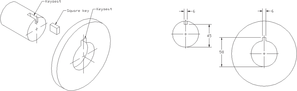
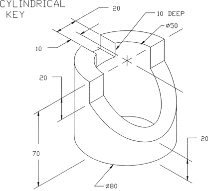
Keys and Keyseats
Keys are small pieces of material used to transmit power. For example, Figure 7-74 shows how a key can be fitted between a shaft and a gear so that the rotary motion of the shaft can be transmitted to the gear.
A small piece of material used to transmit power, such as rotary motion from a shaft to a gear.
There are many different styles of keys. See the keys listed on the Content Center under Shaft Parts. The key shown in Figure 7-74 has a rectangular cross section and is called a square key. Keys fit into grooves called keyseats or keyways.
Keyways are dimensioned from the bottom of the shaft or hole as shown.
A groove into which a key fits; also called keyway.
Symbols and Abbreviations
Symbols are used in dimensioning to help accurately display the meaning of the dimension. Symbols also help eliminate language barriers when reading drawings. Figure 7-75 shows a list of dimensioning symbols available on the Style and Standard Editor dialog box accessed by clicking the Styles Editor under the Manage tab, and clicking the Notes and Leaders tab. How to apply symbols to dimensions was explained earlier in the chapter.
Figure 7-75
Abbreviations should be used very carefully on drawings. Whenever possible, write out the full word, including correct punctuation. Figure 7-76 shows several standard abbreviations used on technical drawings.
Figure 7-76
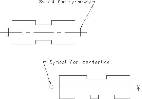
Symmetrical and Centerline Symbols
An object is symmetrical about an axis when one side is an exact mirror image of the other. Figure 7-77 shows a symmetrical object. The two short parallel lines symbol or the note OBJECT IS SYMMETRICAL ABOUT THIS AXIS (centerline) may be used to designate symmetry.
Figure 7-77
If an object is symmetrical, only half the object need be dimensioned. The other dimensions are implied by the symmetry note or symbol.
Centerlines are slightly different from the axis of symmetry. An object may or may not be symmetrical about its centerline. See Figure 7-77. Centerlines are used to define the center of both individual features and entire objects. Use the centerline symbol when a line is a centerline, but do not use it in place of the symmetry symbol.
Dimensioning to a Point
Curved surfaces can be dimensioned using theoretical points. See Figure 7-78. There should be a small gap between the surface of the object and the lines used to define the theoretical point. The point should be defined by the intersection of at least two lines.
Figure 7-78
There should also be a small gap between the extension lines and the theoretical point used to locate the point.
Dimensioning Section Views
Section views are dimensioned, as are orthographic views. See Figure 7-79. The section lines should be drawn at an angle that allows the viewer to distinguish clearly between the section lines and the extension lines.
Figure 7-79
Dimensioning Orthographic Views
Dimensions should be added to orthographic views where the features appear in contour. Holes should be dimensioned in their circular views. Figure 7-80 shows three views of an object that has been dimensioned.
Figure 7-80
The hole dimensions are added to the top view, where the hole appears circular. The slot is also dimensioned in the top view because it appears in contour. The slanted surface is dimensioned in the front view.
The height of surface A is given in the side view rather than run along extension lines across the front view. The length of surface A is given in the front view. This is a contour view of the surface.
It is considered good practice to keep dimensions in groups. This makes it easier for the viewer to find dimensions.
Be careful not to double-dimension a distance. A distance should be dimensioned only once. If a 30 dimension were added above the 25 dimension on the right-side view, it would be an error. The distance would be double dimensioned: once with the 25 + 30 dimension and again with the 55 overall dimension. The 25 + 30 dimensions are mathematically equal to the 55 overall dimension, but there is a distinct difference in how they affect the manufacturing tolerances. Double dimensions are explained more fully in Chapter 8.
Dimensions Using Centerlines
Figure 7-81 shows an object dimensioned from its centerline. This type of dimensioning is used when the distance between the holes relative to each other is critical.
Figure 7-81
3D Dimensions
Inventor can be used to create dimensions on a three-dimensional object. Figure 7-82 shows an object drawn using the ANSI (mm).idw format. The drawing shows a front orthographic view of the object and an isometric view projected from the front view. Figure 7-83 shows the isometric view dimensioned. The Dimension tool was used to create the 3D dimensions. The procedure for creating 3D dimensions is the same as for 2D dimensioning.
Figure 7-82
Figure 7-83
Sample Problem SP7-2
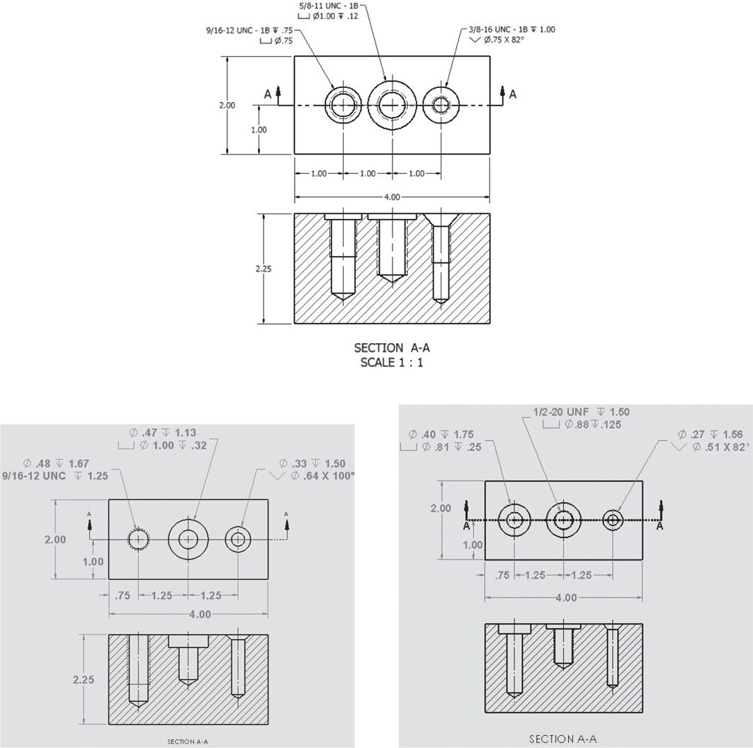
Figure 7-84 shows a shape that is to be dimensioned. All dimensions are in inches. The object is .50 thick.
Figure 7-84
The general procedure for applying dimensions is to start from the center of the shape and work out.
For example, in this example, the hole and cutout are dimensioned first. The leader line for the hole is placed last, as it can be located in many different positions to avoid existing extension and dimension lines.
Dimension the rectangular cutout.
Click the left edge line first to ensure that the .50 dimension is on the outside left of the extension lines.
Tip
Every hole requires three dimensions: two for location and one for diameter.
Dimension the hole’s location.
Dimension the circular cutout.
Use the Leader Text tool.
Add the overall dimensions.
Locate the overall dimensions so that there is an open area for the chamfer note and the hole’s diameter.
Use the Chamfer Note tool and dimension the chamfers.
Edit the chamfer note to include 2 PLACES.
Use the Hole and Thread Notes tool to dimension the hole’s diameter.
Sample Problem SP7-3
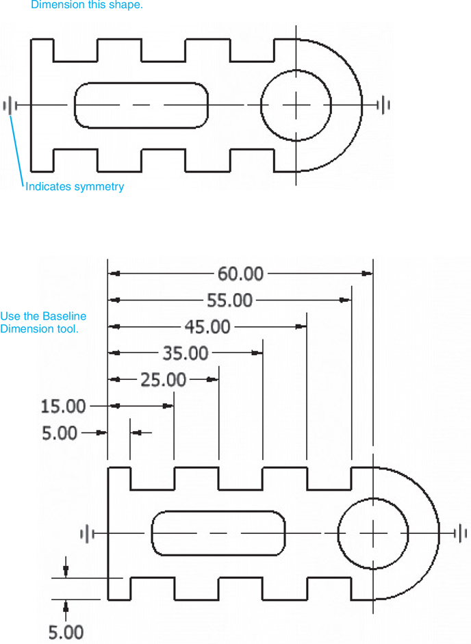
Figure 7-85 shows a shape to be dimensioned. All dimensions are in millimeters. The object is 10 thick.
Figure 7-85
The shape is unusual in that one end is rounded. It is difficult to create an overall dimension to a rounded surface. There are tolerances in both the shape of the circular end (how round it is) and in the location of the arc’s center point. In this example, a reference dimension will be used.
Note that the shape is symmetrical about its horizontal centerline. A symmetrical shape is one that is exactly the same on both sides of a centerline.
Define the object as symmetrical about its horizontal centerline by adding the symbol for symmetry.
The symbol for symmetry is created using the Text tool.
Use the Baseline Dimension tool and dimension the cutouts along the top edge of the part.
Note that the 5.00 depth was located along the bottom edge of the part. This was done to allow space for the internal slot’s dimensions.
Dimension the internal slot.
Position the dimension values so that they do not interfere with other dimensions.
Use the Hole and Thread Notes tool and dimension the hole.
Use the Leader tool and add the radius for the rounded end.
The R30 dimension defines the width of the part, so no other dimension is needed.
Add overall reference dimensions for the length and width.
Reference dimensions are indicated by parentheses. Reference dimensions are not to be used for manufacture or inspection. These are included on a drawing for convenience.
Use the Text tool and add a note defining the fillet size for the internal slot.
There are several different ways to dimension the shape shown in Figure 7-85. Consider chain dimensions or ordinate dimensions as two other possible methods.
Chapter Summary
This chapter explained how to dimension objects with different shapes and features. It presented the ANSI standards and conventions and showed how to dimension different shapes and features, including various types of holes, slanted surfaces, fillets, and rounds. Drawing scales and dimensional values were discussed, including the use of leading zeros with decimal notation and the appropriate use of numbers of decimal places in a dimensional value. Dimensioning of sectional and orthographic views was also illustrated.
Chapter Test Questions
Multiple Choice
Circle the correct answer.
1. When dimensions are drawn, lines that have gaps for numerical values that end with arrowheads are called
a. Centerlines
b. Extension lines
c. Dimension lines
d. Leader lines
2. When dimensions are drawn, lines that project away from the surface of the part are called
a. Centerlines
b. Extension lines
c. Dimension lines
d. Leader lines
3. When dimensions are drawn, lines used to define hole diameters are called
a. Centerlines
b. Extension lines
c. Dimension lines
d. Leader lines
4. Polar dimensions are created using
a. Two linear dimensions
b. A linear and an angular dimension
c. Two angular dimensions
5. Which of the following is not a type of knurl?
a. Crosshatch
b. Diamond
c. Straight
d. Raised diamond
6. A drawing scale designation of 2 5 1 indicates that the shape on the drawing is related how to the actual part?
a. The shape is twice as big.
b. The shape is the same size.
c. The shape is half the size.
7. To edit a center mark’s size,
a. Use the Feature Control frame option on the Style and Standard Editor dialog box.
b. Use the Dimension option on the Style and Standard Editor dialog box.
c. Use the Center Mark option on the Style and Standard Editor dialog box.
8. Dimensions created using the ANSI standards have decimal points (5.25). Dimensions created using the ISO standards use
a. Decimal points
b. Commas
c. Semicolons
d. En dashes
9. Dimensions that define straight distances are called
a. Linear dimensions
b. Angular dimensions
c. Horizontal dimensions
10. The rule for crossing extension lines states that it
a. Is recommended
b. Should be avoided
c. Is never allowed
Matching
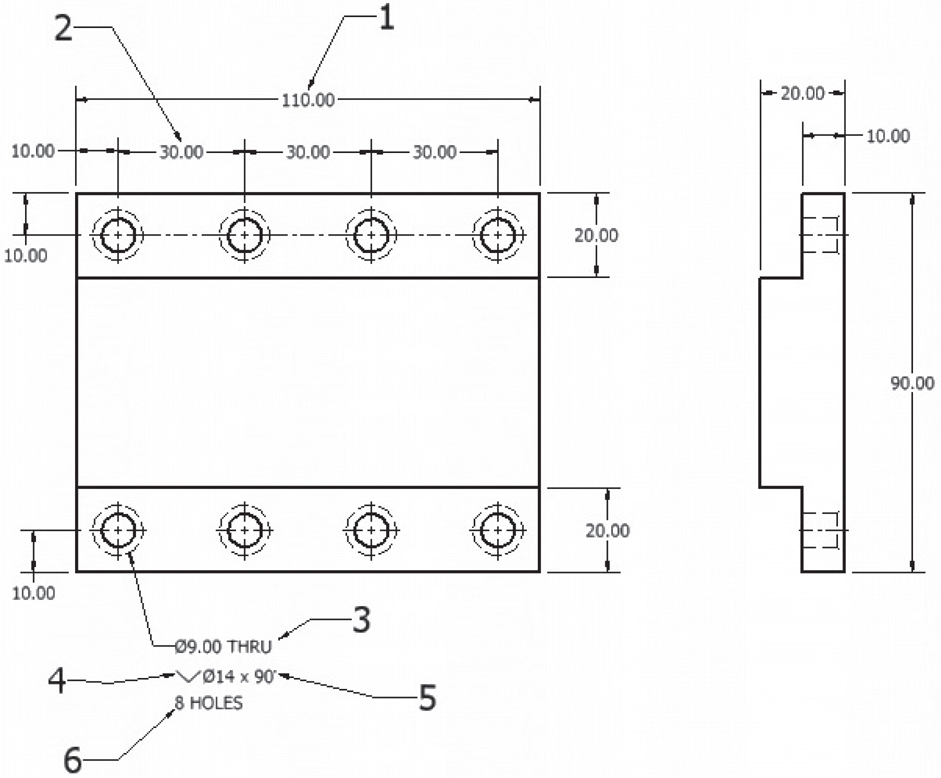
Figure 7-86 shows a dimensioned object. Match the numbers with the type of dimension.
Figure 7-86
Column A
Column B
a. The symbol for countersink __________
b. Indicates that the hole goes completely through the part __________
c. The inclusive angle for the countersink __________
d. An overall dimension __________
e. Indicates the number of Ø9 holes on the part __________
f. A chain dimension __________
True or False
Circle the correct answer.
1. True or False: Dimensions are located on a drawing in compliance with ANSI standards.
2. True or False: Model dimensions are used to construct a shape but do not appear on the ANSI.idw drawing.
3. True or False: Dimensions may be located on the surface of a part.
4. True or False: Dimensions are added to an ANSI.idw drawing using the Dimension tool located on the Annotate tab.
5. True or False: All dimensional values must be located using the unidirectional format.
6. True or False: To edit an existing hole dimension, right-click the dimension and select the Edit Hole Note option.
7. True or False: Inch dimensions that are less than 1.00 require a 0 to the left of the decimal point.
8. True or False: Metric dimensions that are less than 1.00 require a 0 to the left of the decimal point.
9. True or False: Aligned dimensions must be written using the unidirectional format.
10. True or False: A counterbored hole is best dimensioned using a note.
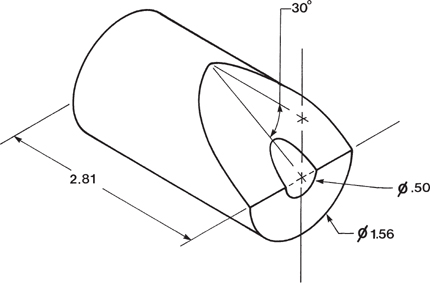
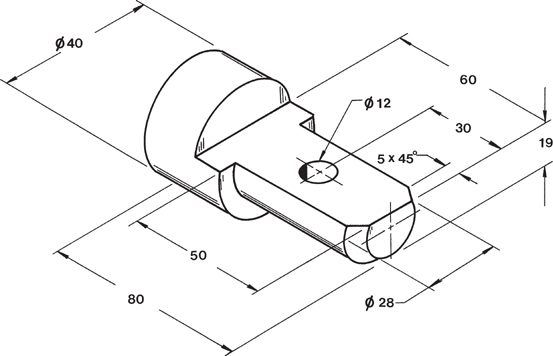
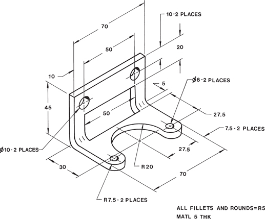
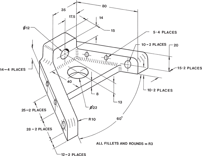
Chapter Projects
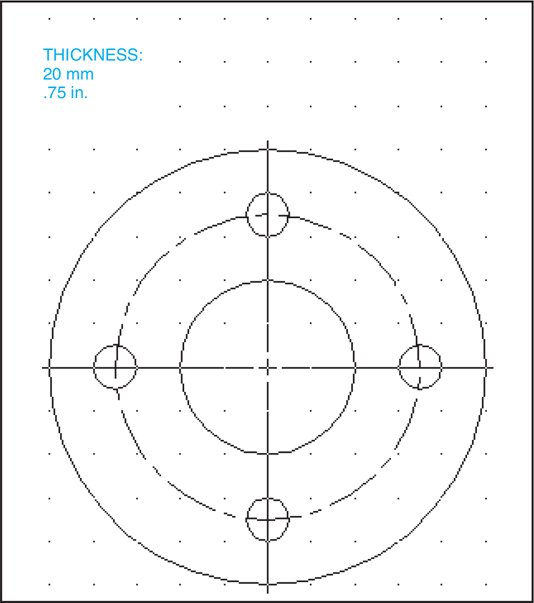
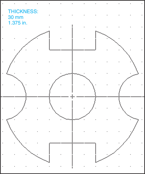
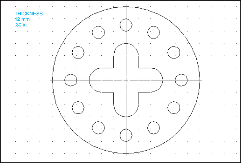
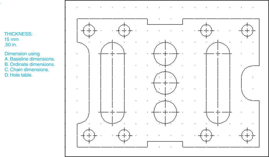
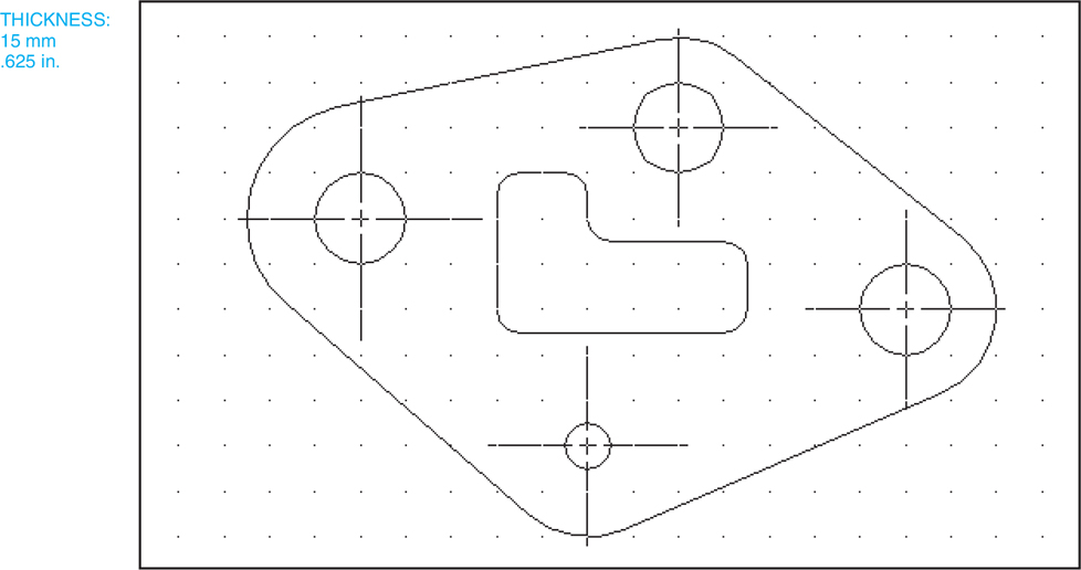
Project 7-1
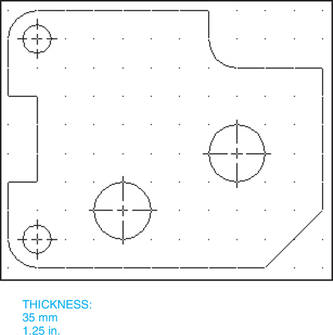
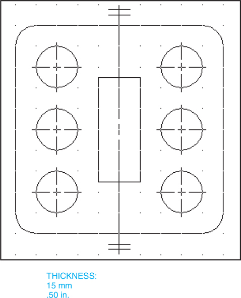
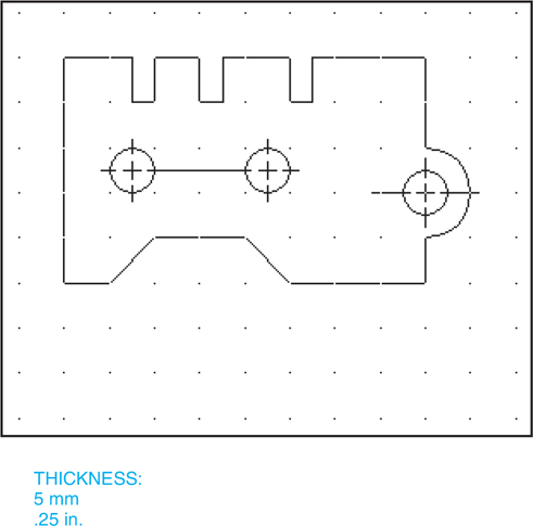
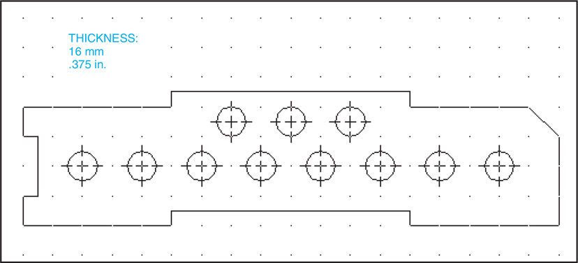
Measure and redraw the shapes in Figures P7-1 through P7-18. The dotted grid background has either .50-in. or 10-mm spacing. All holes are through holes. Specify the units and scale of the drawing. Create a model by using the Extrude tool. Create a set of multiviews (front, top, side, and isometric views) using the .idw format and add the appropriate dimensions.
A. Measure using millimeters.
B. Measure using inches.
All dimensions are within either .25 in. or 5 mm. All fillets and rounds are R.50 in., R.25 in. or R10 mm, R5 mm.