Chapter Six. Threads and Fasteners
Chapter Objectives
Learn thread terminology and conventions
Learn how to draw threads
Learn how to size both internal and external threads
Learn how to use standard-size threads
Learn how to use and size washers, nuts, and setscrews
Introduction
This chapter explains how to draw threads and washers. It also explains how to select fasteners and how to design using fasteners, washers, and keys.
Threads are created in Inventor using either the Hole or the Thread tool located on the Modify panel under the 3D Model tab. See Figure 6-1. Predrawn fasteners may be accessed using the Content Center tool. The Content Center library is explained later in the chapter.

Figure 6-1
Thread Terminology
Figure 6-2 shows a thread. The peak of a thread is called the crest, and the valley portion is called the root. The major diameter of a thread is the distance across the thread from crest to crest. The minor diameter is the distance across the thread from root to root.
The peak of a thread.
The valley of a thread.
The distance across a thread from crest to crest.
The distance across a thread from root to root.

Figure 6-2
Thread Callouts—Metric Units
Threads are specified on a drawing using drawing callouts. See Figure 6-3. The M at the beginning of a drawing callout specifies that the callout is for a metric thread. Holes that are not threaded use the Ø symbol.

Figure 6-3
The number following the M is the major diameter of the thread. An M10 thread has a major diameter of 10 mm. The pitch of a metric thread is assumed to be a coarse thread unless otherwise stated. The callout M10 × 30 assumes a coarse thread, or a thread length of 1.5 mm per thread. The number 30 is the thread length in millimeters. The “×” is read as “by,” so the thread is called a “ten by thirty.”
The callout M10 × 1.25 × 30 specifies a pitch of 1.25 mm per thread. This is not a standard coarse thread size, so the pitch must be specified.
Figure 6-4 shows a listing of preferred sizes for a diameter of 10 cylinder.

Figure 6-4
![]() Click the Thread tool located under the 3D model tab, then click the surface of the cylinder.
Click the Thread tool located under the 3D model tab, then click the surface of the cylinder.
![]() Click the arrowhead next to the Designation box.
Click the arrowhead next to the Designation box.
A listing of thread sizes are available for a diameter 19 cylinder.
![]() Click the arrowhead next to the Size box for a listing of preferred diameter sizes.
Click the arrowhead next to the Size box for a listing of preferred diameter sizes.
Whenever possible, use preferred thread sizes for designing. Preferred thread sizes are readily available and are usually cheaper than nonstandard sizes. In addition, tooling—such as wrenches—is also readily available for preferred sizes.
Thread Callouts—ANSI Unified Screw Threads
ANSI Unified screw threads (English units) always include a thread form specification. Thread form specifications are designated by capital letters, as shown in Figure 6-5, and are defined as follows.

Figure 6-5
UNC—Unified National Coarse
UNF—Unified National Fine
UNEF—Unified National Extra Fine
UN—Unified National, or constant-pitch threads
An ANSI (English units) thread callout starts by defining the major diameter of the thread followed by the pitch specification. The callout .500-13 UNC means a thread whose major diameter is .500 in. with 13 threads per inch. The thread is manufactured to the UNC standards.
There are three possible classes of fit for a thread: 1, 2, and 3. The different class specifications specify a set of manufacturing tolerances. A class 1 thread is the loosest, and a class 3 the most exact. A class 2 fit is the most common.
The letter A designates an external thread, and B designates an internal thread. The symbol × means “by,” as in 2 × 4, “two by four.” The thread length (3.00) may be followed by the word LONG to prevent confusion about which value represents the length.
Pitch is defined as 1/number of threads per inch. ANSI English thread callouts specify the number of threads per inch; so, for example, a .500-13 UNC thread would have a pitch equal to 1/13, or .077 inch. ANSI metric thread designations specify the pitch directly.
Drawing callouts for ANSI (English unit) threads are sometimes shortened, such as in Figure 6-5. The callout .500-13 UNC-2A × 3.00 LONG is shortened to .500-13 × 3.00. Only a coarse thread has 13 threads per inch, and it should be obvious whether a thread is internal or external, so these specifications may be dropped. Most threads are class 2, so it is tacitly accepted that all threads are class 2 unless otherwise specified. The shortened callout form is not universally accepted. When in doubt, use a complete thread callout.
A listing of standard ANSI (English unit) threads, as presented in Inventor, is shown in Figure 6-6. Some of the drill sizes listed use numbers and letters. The decimal equivalents to the numbers are listed in Figure 6-6.

Figure 6-6
Thread Representations
There are three ways to represent threads graphically on a technical drawing: detailed, schematic, and simplified. Figure 6-5 shows an external detailed representation, and Figure 6-7 shows both the external and internal simplified and schematic representations.

Figure 6-7
Figure 6-8 shows an internal and an external thread created using Inventor. The threads will automatically be sized to the existing hole. Threads may be created only around existing holes and cylinders.

Figure 6-8
Internal Threads
Figure 6-9 shows a 20 × 30 × 10 box with a Ø6.0 hole drilled through its center. The hole was created using the Hole tool.

Figure 6-9
Exercise 6-1 Adding Threads to an Existing Hole
![]() Click on the Thread tool located on the Modify panel under the 3D Model tab.
Click on the Thread tool located on the Modify panel under the 3D Model tab.
The Thread dialog box will appear. See Figures 6-4, 6-6, and 6-9.
![]() Click on the existing hole (the internal surface).
Click on the existing hole (the internal surface).
The threads will automatically be created to match the hole’s diameter. Because the hole’s diameter is 6.0, an M6 × 1 thread is created.
![]() Click OK.
Click OK.
Figure 6-10 shows the resulting threaded hole.

Figure 6-10
When a thread is added to an existing hole, a thread listing will be included in the browser box. See Figure 6-11. The listing will confirm that a thread has been added, but it will not define the size or type of thread.

Figure 6-11
Exercise 6-2 Determining the Thread Size
![]() Right-click on the Hole1 listing in the browser box.
Right-click on the Hole1 listing in the browser box.
A dialog box will appear. See Figure 6-12

Figure 6-12
![]() Select the Show Dimensions option.
Select the Show Dimensions option.
Figure 6-13 shows the resulting dimensions. The dimensions define the hole’s diameter, and because Inventor will match the thread size to the existing hole diameter, the thread is an M6.

Figure 6-13
Threaded Blind Holes
The internally threaded holes presented in the last section passed completely through the material. This section shows how to draw holes that do not pass completely through the object but have a defined depth.
Figure 6-14 shows a tapped hole. It is drawn using the simplified representation. Note that there are three separate portions to the hole’s representation: the threaded portion, the unthreaded portion, and the 120° conical point. Only the threaded portion of the tapped hole is used to define the hole’s depth. The unthreaded portion and the conical point are shown, but are not included in the depth calculation.

Figure 6-14
A tapped hole is manufactured by first drilling a pilot hole that is slightly smaller than the major diameter of the threads. The threads are then cut into the side of the pilot hole using a tapping bit. The tapping bit has no cutting edges on its bottom surface, so if it strikes the bottom of the hole, the bit can be damaged. Convention calls for the unthreaded portion of the pilot hole to extend about the equivalent of two thread pitches (2P) beyond the end of the threaded portion. The conical portion is added to the bottom surface of the pilot hole.
Drawing a Threaded Blind Hole—Metric
Figure 6-15 shows a 20 × 30 × 30 box with an existing Ø8 × 16 deep hole. The Thread tool will automatically apply an M8 thread to the Ø8 hole.

Figure 6-15
A minimum distance equal to two pitches (2P) is recommended between the bottom of the hole and the end of the threads. The distance may be greater. One pitch equals 1.25 mm, so 2P = 2.50 mm. The existing hole is 16 mm, so the thread depth is 13.5 mm.
Note
The 2P recommendation is a minimal value. Distances of 3P, 4P, or greater may be used, depending on the application.
Exercise 6-3 Creating a Threaded Blind Hole
![]() Click on the Thread tool on the Modify panel located under the 3D Model tab.
Click on the Thread tool on the Modify panel located under the 3D Model tab.
The Thread dialog box will appear. See Figure 6-16.

Figure 6-16
The Face tool will automatically be activated.
![]() Select Face by clicking the internal surface of the hole.
Select Face by clicking the internal surface of the hole.
![]() Enter a Depth value of 13.5.
Enter a Depth value of 13.5.
![]() Click the Specification tab and set the Designation for M8 × 1.25.
Click the Specification tab and set the Designation for M8 × 1.25.
![]() Click OK.
Click OK.
Note
Inventor will automatically create a coarse thread with a pitch of 1.25. There are other pitch sizes available: M8 × 1, M8 × 0.8, M8 × 0.75, and M8 × 0.5. These pitch sizes are accessed using the arrow on the right side of the Designation box on the Specification tab of the Thread dialog box.
Figure 6-17 shows a section view of the threaded blind hole. Note how hidden lines are used to represent threads in both the top and the section views.

Figure 6-17
Drawing a Blind Hole—ANSI Threads
Pitch for ANSI threads is defined as threads per inch. A ¼-20 UNC thread has a pitch of 20 threads per inch. The length in inches of one thread is 1/20, or 0.05 in. Therefore, 2P = 2(0.05) = 0.10 in.
If a block includes a hole 1.50 deep, then the appropriate thread length is 1.50 − 0.10 = 1.40 in.
Creating Threaded Holes Using the Hole Tool
Threaded holes may be created directly using the Hole tool. Figure 6-18 shows a 30 × 40 × 30 mm block with a hole center defined using the Point, Center Point tool in the center of the top surface.

Figure 6-18
Exercise 6-4 Creating a Threaded Through Hole
![]() Create a new sketch plane on the top surface of the block and use the Point tool to locate a point at the center of the surface.
Create a new sketch plane on the top surface of the block and use the Point tool to locate a point at the center of the surface.
![]() Right-click the mouse and select the Finish 2D Sketch option.
Right-click the mouse and select the Finish 2D Sketch option.
![]() Click on the Hole tool on the Modify panel under the 3D Model tab.
Click on the Hole tool on the Modify panel under the 3D Model tab.
The Hole dialog box will appear. See Figure 6-18.
![]() Click the Termination box and select the Through All option.
Click the Termination box and select the Through All option.
![]() Click the Tapped Hole button.
Click the Tapped Hole button.
![]() Click on Thread Type. Select the ANSI Metric M Profile option.
Click on Thread Type. Select the ANSI Metric M Profile option.
See Figure 6-19

Figure 6-19
![]() Set the thread Size for 10. Select the M10 × 1.5 pitch in the Designation box.
Set the thread Size for 10. Select the M10 × 1.5 pitch in the Designation box.
More than one pitch size is available. In addition to the 1.50 pitch, a 1.25 or 0.75 option is also available. These are Fine and Extra Fine designations. See Figure 6-20.

Figure 6-20
![]() Click OK.
Click OK.
Exercise 6-5 Creating a Threaded Blind Hole
Create a 30 × 40 × 30-mm block with a hole’s center defined in the center of the top surface.
![]() Click on the Hole tool.
Click on the Hole tool.
The Hole dialog box will appear. See Figure 6-21.

Figure 6-21
![]() Set the Termination for Distance, and click the Tapped Hole button.
Set the Termination for Distance, and click the Tapped Hole button.
![]() Set the Size for 10 and the Designation for M10 × 1.5.
Set the Size for 10 and the Designation for M10 × 1.5.
![]() Click the Full Depth box so that no check appears.
Click the Full Depth box so that no check appears.
![]() Set the thread depth for 8 and the hole depth for 10.
Set the thread depth for 8 and the hole depth for 10.
The hole depth should, with rare exceptions, be greater than the thread depth.
![]() Click OK.
Click OK.
Standard Fasteners
Fasteners, such as screws and bolts, and their associated hardware, such as nuts and washers, are manufactured to standard specifications. Using standard-size fasteners in designs saves production costs and helps assure interchangeability.
Inventor includes a library of standard parts that may be accessed using the Place from Content Center tool on the Component panel under the Assemble tab. Clicking on the Place from Content Center tool accesses the Content Center dialog box. The Content Center may also be accessed by right clicking the mouse and selecting the Place from Content Center option.
Note
The drawing must be in the Standard.iam format, either mm or inch designation.
See Figure 6-22. Figure 6-23 shows the Place from Content Center dialog box. Click the + sign to the left of the Fasteners heading under Category View. Click Fasteners, Bolts, Hex Head, and select the Hex Bolt-Metric bolt. A listing of available diameters and lengths will appear. See Figure 6-24. Click the Table View tab to access a table of sizes and dimensions that apply to the selected bolt. See Figure 6-25.

Figure 6-22

Figure 6-23

Figure 6-24

Figure 6-25
Sizing a Threaded Hole to Accept a Screw
Say we wish to determine the length of thread and the depth of hole needed to accept an M10 × 25 hex-head screw and to create a drawing of the screw in the threaded hole. The length of the threaded hole must extend a minimum of two pitches (2P) beyond the end of the screw, and the untapped portion of the hole must extend a minimum of two pitches (2P) beyond the threaded portion of the hole. This requirement ensures that all the fastener threads will be in contact with the hole’s threads and that fasteners will not bottom out. In this example, the thread pitch equals 1.50 mm. Therefore, 2P = 2(1.50) = 3.0 mm. This is the minimum distance and can be increased, but never decreased. See Figure 6-26.

Figure 6-26
The two-pitch length requirement for the distance between the end of the screw and the end of the threaded portion of the hole determines that the thread depth should be 25.0 + 3.0 = 28.0 mm. The two-pitch length requirement between the end of the threaded portion of the hole and the bottom of the hole requires that the hole must have a depth of 28.0 + 3.0, or 31.0 mm.
It is important that complete hole depths be specified, as they will serve to show any interference with other holes or surfaces.
Exercise 6-6 Drawing a Blind Threaded Hole
![]() Create a new Standard (mm).ipt drawing and create a 40 × 40 × 60 block.
Create a new Standard (mm).ipt drawing and create a 40 × 40 × 60 block.
![]() Use the Point, Center Point and the Hole tools to create an M10 × 1.5 × 28 deep thread and a 31 deep hole.
Use the Point, Center Point and the Hole tools to create an M10 × 1.5 × 28 deep thread and a 31 deep hole.
See Figure 6-27.

Figure 6-27
![]() Save the threaded block as Block, Threaded.
Save the threaded block as Block, Threaded.
Exercise 6-7 Creating an Assembly with an M10 × 1.5 × 25 Hex Head Bolt
![]() Create a new Assembly drawing, Standard (mm).iam format called M10ASSEMBLY.
Create a new Assembly drawing, Standard (mm).iam format called M10ASSEMBLY.
![]() Use the Place Component tool and locate one copy of the BLOCK, THREADED block on the drawing screen.
Use the Place Component tool and locate one copy of the BLOCK, THREADED block on the drawing screen.
![]() Click the Place from Content Center tool located on the Component panel under the Assemble tab. The Place from Content Center tool is a flyout from the Place Component tool.
Click the Place from Content Center tool located on the Component panel under the Assemble tab. The Place from Content Center tool is a flyout from the Place Component tool.
The Place from Content Center dialog box will appear. See Figure 6-28.

Figure 6-28
![]() Click the + sign to the left of the Fasteners option. See Figure 6-29.
Click the + sign to the left of the Fasteners option. See Figure 6-29.

Figure 6-29
![]() Click the Bolts option, then click the Hex Head option.
Click the Bolts option, then click the Hex Head option.
![]() Scroll through the options, select Hex Bolt-Metric, and click OK.
Scroll through the options, select Hex Bolt-Metric, and click OK.
A small icon will appear on the screen attached to the cursor
![]() Click the screen.
Click the screen.
A picture of the Hex Bolt-Metric fastener will appear in the dialog box along with a listing of available thread sizes and lengths. See Figure 6-30.

Figure 6-30
![]() Set the nominal diameter for 10, the pitch for 1.5, and the nominal length for 25. The pitch values are listed under the Table View tab.
Set the nominal diameter for 10, the pitch for 1.5, and the nominal length for 25. The pitch values are listed under the Table View tab.
![]() Set the Thread description to M10 and the Nominal Length to 25.
Set the Thread description to M10 and the Nominal Length to 25.
![]() Click the Apply box.
Click the Apply box.
The M10 bolt will appear on the drawing screen with the Block, Threaded. See Figure 6-31. If the bolt interferes with the Block, Threaded, use the Move Component option to position the bolt away from the block. See Figure 6-31. Both the Move and Rotate tools may be used to locate the bolt above the block.

Figure 6-31
Inventor will automatically create a second fastener for insertion.
![]() Press the <Esc> key to remove the second fastener.
Press the <Esc> key to remove the second fastener.
Exercise 6-8 Inserting the M10 Bolt
![]() Click the Constrain tool on the Position panel under the Assemble tab.
Click the Constrain tool on the Position panel under the Assemble tab.
The Place Constraint dialog box will appear. See Figure 6-32.

Figure 6-32
![]() Click the Insert option.
Click the Insert option.
![]() Click the bottom surface of the bolt’s hex head, then click the threaded hole in the BLOCK, THREADED block.
Click the bottom surface of the bolt’s hex head, then click the threaded hole in the BLOCK, THREADED block.
Figure 6-33 shows the resulting assembly.

Figure 6-33
![]() Save the assembly.
Save the assembly.
Figure 6-34 shows a top view and a section view of the M10ASSEMBLY created using the ISO.idw option. Note the open area between the bottom of the M10 bolt and the bottom of the hole.

Figure 6-34
Screws and Nuts
Screws often pass through an object or group of objects and are secured using nuts. The threads of a nut must match the threads of the screw.
Nuts are manufactured at a variety of heights depending on their intended application. Nuts made for heavy loads are thicker than those intended for light loads. In general, nut thickness can be estimated as 0.88 of the major diameter of the thread. For example, if the nut has an M10 thread, the thickness will be about 0.88(10) = 8.8 mm.
It is good practice to specify a screw length that allows for at least two threads beyond the nut. This will ensure that all threads of the nut are in contact with the screw threads. Strength calculations for screw threads are based on 100% contact with the nut. See Figure 6-35.

Figure 6-35
Calculating the Screw Thread Length
In the following example, an M10 bolt will pass through a box that has a height of 30 mm and be held in place using an M10 hex nut. The required length of the screw is calculated by adding the height of the box to the height of the nut, then adding at least two thread lengths (2P).
For an M10 coarse thread 2P = 1.60 mm. The height of the nut = 0.88(10) = 8.80 mm, and the height of the box = 30 mm:
30.00 + 8.80 + 1.60 = 40.4 mm
Refer to Figure 6-30 and find the nearest M10 standard thread length that is greater than 40.4. The table shows the next available standard length that is greater than 40.4 is 45 mm.
Exercise 6-9 Adding an M10 × 45 Hex Head Screw to a Drawing
![]() Draw a 40 × 40 × 30 box.
Draw a 40 × 40 × 30 box.
![]() Locate a Ø11 hole in the center of the top surface of the box.
Locate a Ø11 hole in the center of the top surface of the box.
The hole does not have threads. It is a clearance hole and so should be slightly larger than the M10 thread. See Figure 6-36.

Figure 6-36
![]() Save the block as Ø11BLOCK.
Save the block as Ø11BLOCK.
Exercise 6-10 Adding a Bolt and Nut to the Drawing
![]() Start a new assembly drawing called M10NUT. Use the Standard (mm).iam format.
Start a new assembly drawing called M10NUT. Use the Standard (mm).iam format.
![]() Use the Place Component tool and place a copy of the Ø11BLOCK on the drawing screen.
Use the Place Component tool and place a copy of the Ø11BLOCK on the drawing screen.
![]() Use the Save As command on the File pull-down menu to save and name the new assembly as M10NUT.iam.
Use the Save As command on the File pull-down menu to save and name the new assembly as M10NUT.iam.
![]() Click the Place from Content Center tool.
Click the Place from Content Center tool.
![]() Click the Fasteners option, the Bolts option, the Hex Head option, the Hex Bolt-Metric bolt, and OK.
Click the Fasteners option, the Bolts option, the Hex Head option, the Hex Bolt-Metric bolt, and OK.
A small icon will appear on the screen attached to the cursor.
![]() Click the screen.
Click the screen.
![]() Set the Thread description for M10 and the Nominal Length for 45.
Set the Thread description for M10 and the Nominal Length for 45.
![]() Click the Apply box.
Click the Apply box.
See Figure 6-37

Figure 6-37
![]() Click the Place from Content Center tool, click the Nuts heading in the Category View listing, click the Hex option, and select the Hex Nut-Metric nut. Select the M10 Thread description and Style 1.
Click the Place from Content Center tool, click the Nuts heading in the Category View listing, click the Hex option, and select the Hex Nut-Metric nut. Select the M10 Thread description and Style 1.
See Figure 6-38

Figure 6-38
![]() Click the Apply box.
Click the Apply box.
See Figure 6-39.

Figure 6-39
Inventor will automatically create a second nut for insertion.
![]() Press the <Esc> key to remove the second nut.
Press the <Esc> key to remove the second nut.
Exercise 6-11 Assembling the Components
![]() Click the Constrain tool.
Click the Constrain tool.
![]() Insert the bolt into the hole as described previously.
Insert the bolt into the hole as described previously.
The nut is to be located on the bottom surface of the block, which is presently not visible.
![]() Click the ViewCube and rotate the block so that the bottom surface is visible.
Click the ViewCube and rotate the block so that the bottom surface is visible.
See Figure 6-40

Figure 6-40
![]() Click the Constrain tool and select the Insert option.
Click the Constrain tool and select the Insert option.
![]() Click the bottom of the nut and the edge line of the Ø11 hole.
Click the bottom of the nut and the edge line of the Ø11 hole.
See Figure 6-41

Figure 6-41
![]() Apply the constraints.
Apply the constraints.
Figure 6-42 shows the resulting assembly.

Figure 6-42
Types of Threaded Fasteners
There are many different types of screws generally classified by their head types. Figure 6-43 shows six of the most commonly used types.

Figure 6-43
The choice of head type depends on the screw’s application and design function. A product design for home use would probably use screws that had slotted heads, as most homes possess a blade screwdriver. Hex-head screws can be torqued to higher levels than slotted pan heads but require socket wrenches. Flat-head screws are used when the screw is located in a surface that must be flat and flush.
Sometimes a screw’s head shape is selected to prevent access. For example, the head of the screw used to open most fire hydrants is pentagon-shaped and requires a special wrench to open it. This is to prevent unauthorized access that could affect a district’s water pressure.
Screw connections for oxygen lines in hospitals have left-handed threads. They are the only lines that have left-handed threads, to ensure that no patient needing oxygen is connected to anything but oxygen.
Inventor’s Content Center lists many different types of fasteners. See Figure 6-44. There are many subfiles to each of the fastener headings.

Figure 6-44
Flat-Head Screws—Countersunk Holes
Flat-head screws are inserted into countersunk holes. The procedure is first to create a countersunk hole on a component, then to create an assembly using the component along with the appropriate screw listed in the Content Center.
The following example uses an M8 × 50 Forged Hexagon Socket Flat Countersunk Head Cap Screw-Metric.
The hole in the block must be sized to accept the M8 × 50 screw. This information is available from the Table View option of the Place from Content Center dialog box. See Figure 6-45. For example, the table defines the screw’s head diameter. This value will be used to size the countersunk hole in the 40 × 40 × 80 block. In this example, the head diameter is 15.65 mm.

Figure 6-45
Exercise 6-12 Creating a Countersunk Hole
![]() Create a 40 × 40 × 80 block.
Create a 40 × 40 × 80 block.
![]() Locate a hole’s center point in the center (20 × 20) of the top surface of the block using the Point, Center Point tool.
Locate a hole’s center point in the center (20 × 20) of the top surface of the block using the Point, Center Point tool.
![]() Go to the 3D Model tab and click the Hole tool.
Go to the 3D Model tab and click the Hole tool.
![]() Click the Countersink and Tapped boxes.
Click the Countersink and Tapped boxes.
See Figure 6-46.

Figure 6-46
The pitch length of an M8 thread is 1.25, so two thread lengths (2P) equals 2.50.
The hole’s threads must be at least 50.00 + 2.50 = 52.50, and the pilot hole must be at least 52.50 + 2.50 = 55.00 deep
![]() Click the Full Depth box (remove the check mark), set the Termination option to Distance, set the Thread Type option for ANSI Metric M Profile, the thread depth for 52.5, the hole’s depth for 55, and the head diameter for 15.65.
Click the Full Depth box (remove the check mark), set the Termination option to Distance, set the Thread Type option for ANSI Metric M Profile, the thread depth for 52.5, the hole’s depth for 55, and the head diameter for 15.65.
The value 15.65 came from the Table View portion of the Place from Content Center dialog box. Figure 6-47 shows the countersunk hole located in the 40 × 40 × 80 block.

Figure 6-47
![]() Save the block as BLOCK, COUNTERSINK.
Save the block as BLOCK, COUNTERSINK.
Exercise 6-13 Creating and Inserting a Flat Head Screw
![]() Create an assembly drawing using the Standard (mm).iam format.
Create an assembly drawing using the Standard (mm).iam format.
![]() Use the Place Component tool and locate one copy of the BLOCK, COUNTERSINK on the drawing screen.
Use the Place Component tool and locate one copy of the BLOCK, COUNTERSINK on the drawing screen.
![]() Use the Save As command to save and name the assembly.
Use the Save As command to save and name the assembly.
In this example, the name COUNTERSINK ASSEMBLY was used.
![]() Click the Place from Content Center tool.
Click the Place from Content Center tool.
![]() Select the Fasteners, Bolts option, then Countersunk.
Select the Fasteners, Bolts option, then Countersunk.
![]() Select the Forged Hexagon Socket Flat Countersunk Head Cap Screw—Metric and set the Thread description for M8 and the Nominal Length for 50.
Select the Forged Hexagon Socket Flat Countersunk Head Cap Screw—Metric and set the Thread description for M8 and the Nominal Length for 50.
See Figure 6-48

Figure 6-48
![]() Click the Insert box.
Click the Insert box.
![]() Click the Constrain tool, then select the Insert option on the Place Constraint dialog box.
Click the Constrain tool, then select the Insert option on the Place Constraint dialog box.
![]() Insert the screw into the block.
Insert the screw into the block.
Figure 6-49 shows the resulting assembly. Figure 6-50 shows a top and a section view of the countersunk screw inserted into the block. Note that the portion of the hole below the bottom of the M8 × 50 screw is clear; that is, it does not show the unused threads. This is a drawing convention that is intended to add clarity to the drawing. Inventor will automatically omit the unused threads.

Figure 6-49

Figure 6-50
Counterbores
A counterbored hole is created by first drilling a hole, then drilling a second larger hole aligned with the first. Counterbored holes are often used to recess the heads of fasteners.
Say we wish to fit a 3/8-16 UNC × 1.50 LONG hex-head screw into a block that includes a counterbored hole, and that after assembly the head of the screw is to be below the surface of the block.
Determining the Counterbore Depth
It is necessary to access the Content Center to find the head height of the bolt to be able to determine the depth of the counterbore.
Exercise 6-14 Determining the Head Height of a Bolt
![]() Create a new assembly drawing and click the Place from Content Center tool.
Create a new assembly drawing and click the Place from Content Center tool.
![]() Click Fasteners, Bolts, and Hex Head to access the hex head bolt listing.
Click Fasteners, Bolts, and Hex Head to access the hex head bolt listing.
![]() Select the Hex Bolt - Inch bolt.
Select the Hex Bolt - Inch bolt.
The Hex Bolt - Inch dialog box will appear. See Figure 6-51.

Figure 6-51
![]() Select the 3/8-16 UNC × 1.50 LONG bolt.
Select the 3/8-16 UNC × 1.50 LONG bolt.
![]() Click the Table View tab.
Click the Table View tab.
See Figure 6-43 for reference.
In this example, the head height is 0.268 in. (See Figure 6-51.) The counterbore must have a depth greater than the head height. A distance of 0.313 (5/16) was selected.
Determining the Thread Length
The screw is 1.50 in. long and has a pitch of 16 threads per inch. Each thread is therefore 1/16, or 0.0625 in. It is recommended that there be at least two threads beyond the end of the screw. Two thread pitches would be 2(0.0625) = 0.125 in. This is a minimum recommendation. A larger value could also be used.
The thread depth is 1.50 + 0.125, or 1.625 in. minimum; however, the thread is created below the counterbore, so in Inventor the value must include the depth of the counterbore. The thread depth is 1.625 + 0.313 = 1.938 in.
Determining the Depth of the Hole
The hole should extend at least two pitch lengths beyond the threaded portion of the hole, plus the depth of the counterbore, so 1.938 + 0.125 = 2.063 in.
Determining the Counterbore’s Diameter
The distance across the corners of the screw is listed in the Table View portion of the Place from Content Center dialog box as 0.650 in. The counterbored hole must be at least this large, plus have an allowance for the tool (socket wrench) needed to assemble and disassemble the screw. In general, the diameter is increased 0.125 in., or 1/8 in. [3.2 mm], all around to allow for tooling needs.
If space is a concern, then designers will change the head type of a screw so that the tooling will not add to the required diameter. For example, a socket-head type screw may be used if design requirements permit.
The minimum counterbore diameter is 0.650 + 0.125 = 0.775. The 0.650 value was determined using the .649 distance across the corners value that was found in the Table View in the Hex Bolt-Inch dialog box. The 0.125 value is a tool allowance added so a socket wrench can access the bolt head. For this example, 0.8125, or 13/16 in., was selected. We can now create the component.
Exercise 6-15 Drawing a Counterbored Hole
![]() Draw a 3.00 × 3.00 × 5.00 block using the Standard (in).ipt format.
Draw a 3.00 × 3.00 × 5.00 block using the Standard (in).ipt format.
![]() Locate a hole’s center point in the center of the 3.00 × 3.00 surface.
Locate a hole’s center point in the center of the 3.00 × 3.00 surface.
![]() Click the 3D Model tab and click the Hole tool.
Click the 3D Model tab and click the Hole tool.
The Hole dialog box will appear.
![]() Click the Counterbore, Tapped tools, turn off the Full Depth option, and set the hole type for ANSI Unified Screw Thread.
Click the Counterbore, Tapped tools, turn off the Full Depth option, and set the hole type for ANSI Unified Screw Thread.
![]() Set the hole depth for 2.063, the thread depth for 1.938, the counterbore diameter for .8125, and the counterbore depth for .313.
Set the hole depth for 2.063, the thread depth for 1.938, the counterbore diameter for .8125, and the counterbore depth for .313.
![]() Select 3/8-16 UNC threads.
Select 3/8-16 UNC threads.
See Figure 6-52.

Figure 6-52
![]() Click OK, then save the block as BLOCK, COUNTERBORE.
Click OK, then save the block as BLOCK, COUNTERBORE.
Exercise 6-16 Assembling the Screw
![]() Create an assembly drawing using the Standard (in).iam format.
Create an assembly drawing using the Standard (in).iam format.
![]() Use the Place Component tool to place a copy of the counterbored block on the screen.
Use the Place Component tool to place a copy of the counterbored block on the screen.
![]() Use the Save As command to save and name the assembly COUNTERBORE ASSEMBLY.
Use the Save As command to save and name the assembly COUNTERBORE ASSEMBLY.
![]() Click the Place from Content Center tool and select a 3/8-16 UNC × 1.50 hex-head bolt and insert it onto the drawing.
Click the Place from Content Center tool and select a 3/8-16 UNC × 1.50 hex-head bolt and insert it onto the drawing.
See Figure 6-53.

Figure 6-53
![]() Use the Place Constraint tool to insert the bolt into the hole.
Use the Place Constraint tool to insert the bolt into the hole.
Figure 6-54 shows the bolt inserted into the counterbored hole. Note the tooling clearance around the hex head and the clearance between the top of the bolt and the top surface of the block.

Figure 6-54
Drawing Fasteners Not Included in the Content Center
The Content Center contains a partial listing of fasteners. There are many other sizes and styles available. Inventor can be used to draw specific fasteners that can then be saved and used on assemblies.
Say we wish to draw an M8 × 25 hex-head screw and that this size is not available in the Content Center.
Exercise 6-17 Drawing an M8 × 25 Hex Head Screw
![]() Create a Standard (mm).ipt drawing.
Create a Standard (mm).ipt drawing.
![]() Draw a Ø8 × 25 cylinder. Draw the cylinder with its top surface on the XY plane so that it extends in the negative Z direction.
Draw a Ø8 × 25 cylinder. Draw the cylinder with its top surface on the XY plane so that it extends in the negative Z direction.
See Figure 6-55

Figure 6-55
![]() Add a 1.25 × 1.25 chamfer to the bottom of the cylinder.
Add a 1.25 × 1.25 chamfer to the bottom of the cylinder.
See Figure 6-56. In general, the chamfer will equal approximately one pitch length. The Chamfer tool is located on the Modify panel under the 3D Model tab.

Figure 6-56
![]() Create a new sketch plane on the top surface of the cylinder.
Create a new sketch plane on the top surface of the cylinder.
![]() Use the Polygon tool and draw a hexagon centered on the top surface of the cylinder. Sketch the hexagon 12 mm across the flats (see Chapter 2) and extrude it to a height of 5.4 mm above the XY plane.
Use the Polygon tool and draw a hexagon centered on the top surface of the cylinder. Sketch the hexagon 12 mm across the flats (see Chapter 2) and extrude it to a height of 5.4 mm above the XY plane.
See Figure 6-57.

Figure 6-57
The head height and distance across the flats were determined using the general values defined in Figure 6-43. Specific values may be obtained from manufacturers, many of whom list their products on the Web, or from reference books such as Machinery’s Handbook.
![]() Add threads to the cylinder, using the Thread tool. Click the cylinder, and Inventor will automatically create threads to match the cylinder’s diameter.
Add threads to the cylinder, using the Thread tool. Click the cylinder, and Inventor will automatically create threads to match the cylinder’s diameter.
See Figure 6-58. Check the thread specification to assure that correct threads were created. Note that the coarse pitch of 1.25 was automatically selected, but other pitch values are also available.

Figure 6-58
![]() Save the drawing as M8 × 1.25 × 25 HEXHEADSCREW.
Save the drawing as M8 × 1.25 × 25 HEXHEADSCREW.
Sample Problem SP6-1
Nuts are used with externally threaded objects to hold parts together. There are many different styles of nuts. The Content Center library includes listings for hex, slotted hex, and wing nuts, among others. Figure 6-59 shows the Table View portion of the Content Center dialog box that includes nut heights.

Figure 6-59
The threads of a nut must be exactly the same as the external threads inserted into them. For example, if a screw with an M8 × 1.25 thread is selected, an M8 × 1.25 nut thread must be selected.
The head height of the nut must be considered when determining the length of a bolt. It is good practice to have a minimum of two threads extend beyond the nut to help ensure that the nut is fully secured. Strength calculations are based on all nut threads being 100% engaged, so having threads extend beyond a nut is critical.
Figure 6-60 shows two blocks, each 25-mm thick with a center hole of Ø9.00 mm. The holes are clearance holes and do not include threads. The blocks are to be held together using an M8 hex head screw and a compatible nut.

Figure 6-60
Determining the Minimum Thread Length Required
Each block is 25-mm thick, for a total of 50 mm. The nut height, from Figure 6-59, for an M8 hex nut is 6.80, so the minimum thread length that will pass through both parts and the nut is 56.80 mm. Two threads must extend beyond the nut to ensure that it is fully secured. From Figure 6-59 the length of an M8 thread is given as 1.25 mm, so two threads equal 2.50 mm. Therefore, the minimum thread length must be 50.00 + 6.80 + 2.50 = 59.3 mm.
Bolts are manufactured in standard lengths, some of which are listed in the Content Center library. If the required thread length was not available from the library, manufacturers’ catalogs would have to be searched and a new screw drawing created. In this example, the next available standard length is 60 mm.
Exercise 6-18 Selecting a Screw
![]() Click the Place from Content Center tool.
Click the Place from Content Center tool.
![]() Select the Fasteners option, then Bolts, then Hex Head. Select the Hex Bolt - Metric.
Select the Fasteners option, then Bolts, then Hex Head. Select the Hex Bolt - Metric.
See Figure 6-61. The standard thread length that is closest to, but still greater than, 59.3 is 60 mm. The 60 mm length is selected and applied to the drawing.

Figure 6-61
![]() Define the values for an M8 × 60 hex head screw and insert it into the drawing.
Define the values for an M8 × 60 hex head screw and insert it into the drawing.
See Figure 6-62.

Figure 6-62
![]() Insert the screw into the two assembled parts.
Insert the screw into the two assembled parts.
See Figure 6-63. Note that the screw extends beyond the bottom of the two assembled parts.

Figure 6-63
Exercise 6-19 Selecting a Nut
![]() Click the Place from Content Center and select the Fasteners option, then Nuts, then Hex, then the Hex Nut - Metric listing.
Click the Place from Content Center and select the Fasteners option, then Nuts, then Hex, then the Hex Nut - Metric listing.
See Figure 6-64.

Figure 6-64
![]() Insert a copy of the nut into the drawing area.
Insert a copy of the nut into the drawing area.
Figure 6-65 shows the nut added to the drawing screen.

Figure 6-65
![]() Use the Place Constraint tool and insert the nut onto the screw so that it is flush with the bottom surface of the blocks.
Use the Place Constraint tool and insert the nut onto the screw so that it is flush with the bottom surface of the blocks.
Figure 6-66 shows the nut inserted onto the screw.

Figure 6-66
The nuts listed in the Content Center library represent only a partial listing of the sizes and styles of nuts available. If a design calls for a nut size or type not listed in the Content Center library, refer to manufacturers’ specifications, then draw the nut and save it as an individual drawing. It can then be added to the design drawings as needed.
Washers
Washers are used to increase the bearing area under fasteners or as spacers. Washers are identified by their inside diameter, outside diameter, and thickness. In addition, washers can be designated N, R, or W for narrow, regular, and wide, respectively. These designations apply only to the outside diameters; the inside diameter is the same.
A flat thin ring used to increase the bearing area under a fastener or as a spacer.
Inventor lists washers by their nominal diameter. The nominal diameters differ from the actual inside diameter by a predetermined clearance allowance. For example, a washer with a nominal diameter of 8 has an actual inside diameter of 8.40, or 0.40 mm greater than the 8 nominal diameter. This means that washer sizes can easily be matched to thread sizes using nominal sizes. A washer with a nominal diameter designation of 8 will fit over a thread designated M8.
There are different types of washers including, among others, plain and tapered. The Place from Content Center dialog box includes a listing of both plain and tapered washers. Figure 6-67 shows the Table View portion of the Place from Content Center dialog box for a plain washer ISO 7089.


Figure 6-67
Inserting Washers onto a Fastener
We again start with the two blocks shown in Figure 6-60. Each has a height of 25 mm. We know from the previous section that the nut height is 6.80 mm and that the requirement that at least two threads extend beyond the end of the nut adds 2.50 mm, yielding a total thread length requirement of 59.3. We now have to add the thickness of the two washers and recalculate the minimum required bolt length.
Say we selected a plain regular washer number ISO 7089 with a nominal size of 8. From Figure 6-67, the Table View on the IS0 7089 dialog box the thickness is found to be 1.6 mm, or a total of 3.20 mm for the two washers. This extends the minimum bolt length requirement to 59.3 + 3.20 = 62.5. The nearest standard thread bolt length listed in the Place from Content Center dialog box that is greater than the 62.5 requirement is 65.
Exercise 6-20 Adding Washers to an Assembly
![]() Use the Place Component tool and locate two copies of the block on the drawing, then align the blocks.
Use the Place Component tool and locate two copies of the block on the drawing, then align the blocks.
![]() Use the Save As command to save and name the assembly.
Use the Save As command to save and name the assembly.
![]() Click the Place from Content Center tool and select an M8 × 65 Hex Head screw and an M8 Hex Nut, and insert them into the drawing.
Click the Place from Content Center tool and select an M8 × 65 Hex Head screw and an M8 Hex Nut, and insert them into the drawing.
See Figure 6-68

Figure 6-68
![]() Access the Place from Content Center dialog box and select the Washers option, then Plain, then an ISO 7089 washer.
Access the Place from Content Center dialog box and select the Washers option, then Plain, then an ISO 7089 washer.
See Figure 6-69. Figure 6-67 shows the Table View values for the washer.

Figure 6-69
![]() Insert two copies into the drawing.
Insert two copies into the drawing.
See Figure 6-70

Figure 6-70
![]() Use the Place Constraint, Insert option tool and align the washers with the holes in the blocks.
Use the Place Constraint, Insert option tool and align the washers with the holes in the blocks.
See Figure 6-71

Figure 6-71
![]() Use the Place Constraint tool and insert the M8 × 65 screw and the nut.
Use the Place Constraint tool and insert the M8 × 65 screw and the nut.
Figure 6-72 shows the resulting assembly.

Figure 6-72
The washers listed in the Content Center dialog box library represent only a partial listing of the washers available. If a design calls for a washer size or type not listed in the library, refer to manufacturers’ specifications, then draw the washer and save it as an individual drawing. It can then be added to the design drawings as needed.
Setscrews
Setscrews are fasteners used to hold parts like gears and pulleys to rotating shafts or other moving objects to prevent slippage between the two objects. See Figure 6-73.
A fastener used to hold parts to rotating shafts or other moving objects to prevent slippage between the two objects.

Figure 6-73
Most setscrews have recessed heads to help prevent interference with other parts.
Many different head styles and point styles are available. See Figure 6-74. The dimensions shown in Figure 6-74 are general sizes for use in this book. For actual sizes, see the manufacturer’s specifications.

Figure 6-74
Figure 6-75 shows a collar with two 10(.19)-32UNF threaded holes.

Figure 6-75
Exercise 6-21 Adding a Setscrew
![]() Create an assembly drawing using the Standard (in).iam format.
Create an assembly drawing using the Standard (in).iam format.
![]() Use the Place Component tool and place one copy of the collar on the drawing.
Use the Place Component tool and place one copy of the collar on the drawing.
![]() Use the Save As tool to save and name the assembly.
Use the Save As tool to save and name the assembly.
![]() Access the Place from Content Center dialog box and select the Fasteners option, then Bolts, then Set Screws.
Access the Place from Content Center dialog box and select the Fasteners option, then Bolts, then Set Screws.
![]() Select the Type E - Spline Socket Set Screw - Cup Point - Inch option and set the (nominal diameter) Thread description for #10, the Nominal Length for 0.3125, and the Thread Type for UNF.
Select the Type E - Spline Socket Set Screw - Cup Point - Inch option and set the (nominal diameter) Thread description for #10, the Nominal Length for 0.3125, and the Thread Type for UNF.
See Figure 6-76.

Figure 6-76
![]() Insert a copy of the setscrew on the drawing.
Insert a copy of the setscrew on the drawing.
See Figure 6-77.

Figure 6-77
![]() Use the Place Constraint tool and insert the setscrew into one of the threaded holes.
Use the Place Constraint tool and insert the setscrew into one of the threaded holes.
Figure 6-78 shows the resulting assembly.

Figure 6-78
Rivets
Rivets are fasteners that hold together adjoining or overlapping objects. A rivet starts with a head at one end and a straight shaft at the other end. The rivet is then inserted into the object, and the headless end is “bucked” or otherwise forced into place. A force is applied to the headless end that changes its shape so that another head is formed, holding the objects together.
A metal fastener with a head and a straight shaft for holding together overlapping and adjoining objects.
There are many different shapes and styles of rivets. Figure 6-79 shows five common head shapes for rivets. Hollow rivets are used on aircraft because they are very lightweight. A design advantage of rivets is that they can be drilled out and removed without damage to the objects they hold together.

Figure 6-79
Rivet types are represented on technical drawings using a coding system. See Figure 6-80. Because rivets are sometimes so small and the material they hold together so thin that it is difficult to draw the rivets clearly, some companies draw only the rivet’s centerline in the side view and identify the rivets using a drawing callout.

Figure 6-80
Figure 6-81 shows the Place from Content Center dialog box for plain rivets.

Figure 6-81
Sample Problem SP6-2
Figure 6-82 shows an assembly drawing. The assembly is to be held together using M8 hex-head screws. It was created as follows:

Figure 6-82
![]() Use the Standard (mm).ipt format and create the TOP BRACKET and the SOLID BASE.
Use the Standard (mm).ipt format and create the TOP BRACKET and the SOLID BASE.
This assembly was created using the bottom-up approach. It could also have been created using the top-down approach. Figure 6-83 shows dimensioned drawings of the top bracket and solid base.

Figure 6-83
![]() Assemble two brackets and one base as shown.
Assemble two brackets and one base as shown.
See Figure 6-84.

Figure 6-84
![]() Access the Place from Content Center dialog box.
Access the Place from Content Center dialog box.
![]() Click the Washers heading and select the Plain Washer (Metric).
Click the Washers heading and select the Plain Washer (Metric).
See Figure 6-85.

Figure 6-85
![]() Select a Nominal Diameter of 10.
Select a Nominal Diameter of 10.
See Figure 6-86.

Figure 6-86
![]() Click the Table View tab on the Plain Washer (Metric) dialog box.
Click the Table View tab on the Plain Washer (Metric) dialog box.
See Figure 6-87.

Figure 6-87
![]() Note that the height of the washer is 2.3, the inside diameter is 10.85, and the outside diameter is 20. The washer specification is 10 × 20 × 2.3. The inside nominal diameter is used in the washer specification.
Note that the height of the washer is 2.3, the inside diameter is 10.85, and the outside diameter is 20. The washer specification is 10 × 20 × 2.3. The inside nominal diameter is used in the washer specification.
![]() Click OK.
Click OK.
![]() Add two washers to the assembly drawing.
Add two washers to the assembly drawing.
![]() Use the Insert constraint to locate the washers around the holes on the two top brackets.
Use the Insert constraint to locate the washers around the holes on the two top brackets.
See Figure 6-88.

Figure 6-88
![]() Access the Place from Content Center dialog box.
Access the Place from Content Center dialog box.
![]() Click the Hex heading under Nuts and select the Hex Jam Nut - Metric hex nut option.
Click the Hex heading under Nuts and select the Hex Jam Nut - Metric hex nut option.
See Figure 6-89.

Figure 6-89
![]() Select the M10 thread option.
Select the M10 thread option.
See Figure 6-90.

Figure 6-90
![]() Click the Table View tab on the Hex Jam Nut - Metric dialog box.
Click the Table View tab on the Hex Jam Nut - Metric dialog box.
See Figure 6-91.

Figure 6-91
![]() Note that the height of the nut is 5.0. Scroll the screen to the right and note that the pitch is 1.50.
Note that the height of the nut is 5.0. Scroll the screen to the right and note that the pitch is 1.50.
![]() Click OK.
Click OK.
![]() Add three nuts to the assembly drawing.
Add three nuts to the assembly drawing.
![]() Use the Insert constraint and locate the nuts aligned with the matching holes in the top brackets and with the holes between the top brackets and the solid base as shown.
Use the Insert constraint and locate the nuts aligned with the matching holes in the top brackets and with the holes between the top brackets and the solid base as shown.
See Figure 6-92.

Figure 6-92
![]() Calculate the required screw length for the screw that mounts between the back-to-back top brackets.
Calculate the required screw length for the screw that mounts between the back-to-back top brackets.
The flanges on the two top brackets are 10 each, the washers are 2.30 thick, and the nut is 5.00 thick. Therefore, the minimum screw length is equal to
10 + 10 + 2.30 + 2.30 + 5.00 = 29.60
This length value does not include the required two pitches that must extend beyond the nut.
![]() Access the Place from Content Center and click the Fasteners heading.
Access the Place from Content Center and click the Fasteners heading.
![]() Select the Hex Head option.
Select the Hex Head option.
See Figure 6-93.

Figure 6-93
![]() Select the Hex Bolt - Metric option.
Select the Hex Bolt - Metric option.
See Figure 6-94.

Figure 6-94
![]() Click the Table View tab on the Hex Bolt - Metric dialog box and note that the pitch of the M10 thread is 1.50.
Click the Table View tab on the Hex Bolt - Metric dialog box and note that the pitch of the M10 thread is 1.50.
![]() Click the Select tab on the Hex Bolt - Metric dialog box.
Click the Select tab on the Hex Bolt - Metric dialog box.
The value for 2P (two pitches) equals 2(1.50) = 3.00. Add this value to the 29.60 length requirement calculated previously:
29.60 + 3.00 = 32.60
The next standard length value is 35. See Figure 6-95.

Figure 6-95
![]() Select the 35 nominal length; click OK.
Select the 35 nominal length; click OK.
![]() Use the Insert constraint tool and insert the screw into the assembly.
Use the Insert constraint tool and insert the screw into the assembly.
See Figure 6-96.

Figure 6-96
![]() Calculate the minimum thread length for the two screws inserted between the top bracket and the solid base.
Calculate the minimum thread length for the two screws inserted between the top bracket and the solid base.
From the dimensioned drawings shown in Figure 6-83, the depth of the counterbore on the top bracket is 8.00. The total height of the flange is 24.00, so the threaded portion of each screw must pass through a difference of 16.00. The counterbore on the solid base is 8.00 deep, and the flange is 20 thick, so the thread must pass through 12.00. The total distance is 16.00 + 12.00 = 28.00.
If the same nut as selected previously is used, the nut height is 5.0. The thread pitch for an M10 screw is 1.50 (2P = 3.00). Therefore, the minimum required thread length is as follows:
16.00 + 12.00 + 5.00 + 3.00 = 36.00
This value indicates that an M10 × 40 screw is required.
![]() Use the Insert constraint and position the screws.
Use the Insert constraint and position the screws.
See Figure 6-97.

Figure 6-97
![]() Save the assembly drawing as SP6-1 ASSEMBLY.
Save the assembly drawing as SP6-1 ASSEMBLY.
![]() Close the assembly drawing.
Close the assembly drawing.
![]() Start a new drawing using the Standard (mm).ipn format.
Start a new drawing using the Standard (mm).ipn format.
![]() Click the Create View tool and access the SP6-1 ASSEMBLY.
Click the Create View tool and access the SP6-1 ASSEMBLY.
![]() Use the Tweak Components tool and create an exploded isometric drawing showing all the parts of the assembly.
Use the Tweak Components tool and create an exploded isometric drawing showing all the parts of the assembly.
See Figure 6-98.

Figure 6-98
Tip
Try the animation options.
![]() Save the exploded assembly drawing as SP6-1 ASSEMBLY.
Save the exploded assembly drawing as SP6-1 ASSEMBLY.
![]() Close the assembly drawing.
Close the assembly drawing.
![]() Start a new drawing using the ANSI (mm).idw format.
Start a new drawing using the ANSI (mm).idw format.
![]() Create an Iso Top Left exploded assembly drawing based on the .ipn bracket assembly drawing.
Create an Iso Top Left exploded assembly drawing based on the .ipn bracket assembly drawing.
See Figure 6-99.

Figure 6-99
![]() Add assembly numbers (balloon numbers) to the assembly drawing.
Add assembly numbers (balloon numbers) to the assembly drawing.
Start the assembly numbers with the biggest parts. The solid base should be part 1, the top bracket part 2, and so on.
See Figure 6-100.

Figure 6-100
![]() Click the Parts List tool on the Annotate panel and locate the parts list on the assembly drawing.
Click the Parts List tool on the Annotate panel and locate the parts list on the assembly drawing.
See Figure 6-101. The part numbers that are displayed on the parts list are the file numbers for the parts. These numbers may be edited as needed.

Figure 6-101
Tip
The parts list may be located on a separate sheet if needed.
![]() Right-click the parts list and select the Edit Parts List option. Enter the appropriate part numbers and descriptions as shown.
Right-click the parts list and select the Edit Parts List option. Enter the appropriate part numbers and descriptions as shown.
![]() Click the Column Chooser option.
Click the Column Chooser option.
See Figure 6-102.

Figure 6-102
![]() Scroll down the Available Properties options and add MATERIAL to the parts list.
Scroll down the Available Properties options and add MATERIAL to the parts list.
See Figure 6-103.

Figure 6-103
![]() Use the Move Down option on the Parts List Column Chooser dialog box and move the QTY heading to the bottom of the list.
Use the Move Down option on the Parts List Column Chooser dialog box and move the QTY heading to the bottom of the list.
![]() Click OK.
Click OK.
See Figure 6-104.

Figure 6-104
![]() Add the description and material requirements for the solid base and top brackets.
Add the description and material requirements for the solid base and top brackets.
See Figure 6-105.

Figure 6-105
![]() Click OK.
Click OK.
Figure 6-105 shows the finished isometric exploded assembly drawing.
Chapter Summary
This chapter explained how to draw threads and washers as well as how to select fasteners and how to design using fasteners, washers, and keys.
Thread terminology was explained and illustrated, and the different thread form specifications and ways of graphically representing threads were described, including threaded through holes, internal threads, and blind threaded holes. ANSI standards and conventions were followed.
The Place from Content Center tool was used to specify different types of fasteners in drawings, including bolts and screws coupled with nuts. Countersunk screws and counterbored holes were described and illustrated.
Chapter Test Questions
Multiple Choice
Circle the correct answer.
1. Which of the following is not a type of point for a setscrew?
a. Half dog
b. Cone
c. Cylinder
d. Flat
2. A flat-head fastener is used with which of the following hole shapes?
a. Counterbore
b. Countersink
c. Spotface
3. What is the pitch of a thread designated ¼-20 UNC?
a. 0.05
b. 0.10
c. 0.025
d. 0.20
4. What is the pitch of a thread designated M10 × 1.25 × 20?
a. 1.00
b. 2.00
c. 1.25
d. 1.50
5. Which of the following thread forms has the most threads per inch?
a. UNC
b. UNF
c. UNEF
d. UN
6. If a ½-13 UNC fastener must pass through two parts—a washer and a nut—whose total thickness is 2.50, what is the minimum possible length for the fastener?
a. 2.50
b. 2.65
c. 2.75
d. 2.88
7. The major diameter of a thread is measured from
a. Crest to crest
b. Root to root
c. Two times the pitch
8. Which tool is used to edit an existing threaded hole?
a. Edit Sketch
b. Edit Feature
c. Edit Text
9. If an M8 × 1 × 16 fastener is to be inserted into a threaded hole, the thread depth must be at least
a. 16
b. 17
c. 18
d. 19
10. Which type of thread advances when turned in the clockwise direction?
a. Right-hand
b. Left-hand
c. Center-thread
Matching
Given the following thread callout, identify the meaning of each term. ¼-20 UNC-2A × 1.625
Column A |
Column B |
|---|---|
a. 20__________ |
1. Length |
b. UNC__________ |
2. Class of fit |
c. ¼__________ |
3. External |
d. 1.625__________ |
4. Major diameter |
e. A__________ |
5. Pitch |
f. 2__________ |
6. Thread form |
Given the following thread callout, identify the meaning of each term. M10 × 1.25 × 30
Column A |
Column B |
|---|---|
g. M10 __________ |
7. Length |
h. 1.25 __________ |
8. Thread designation |
i. 30 __________ |
9. Pitch |
True or False
Circle the correct answer.
1. True or False: The notation Ø10 designates either a hole or a cylindrical-shape object, whereas the notation M10 designates either an internal or an external thread.
2. True or False: The pitch of a thread is the linear distance along the thread from crest to crest.
3. True or False: The thread designation M10 × 1.25 × 30 indicates that the thread’s pitch is 30.
4. True or False: A coarse-thread pitch is not included in a metric-thread callout.
5. True or False: The thread designation .500 13 UNC × 3.00 LONG indicates that the thread’s pitch is 13.
6. True or False: UNC, UNF, UNEF, and UN are all standard thread forms.
7. True or False: Threads can be drawn in Inventor using the Hole tool on the 3D Model tab.
8. True or False: The threaded portion of an internal hole must extend at least two pitches beyond the end of the fastener inserted into the hole.
9. True or False: The Inventor Content Center includes a listing of standard threaded fasteners.
10. True or False: A washer is defined using the inside diameter × outside diameter × thickness.
Chapter Project
Project 6-1: Millimeters
Figure P6-1 shows three blocks. Assume that the blocks are each 30 × 30 × 10 and that the hole is Ø9. Assemble the three blocks so that their holes are aligned and they are held together by a hex-head bolt secured by an appropriate hex nut. Locate a washer between the bolt head and the top block and between the nut and the bottom block. Create all drawings using either an A4 or an A3 drawing sheet, as needed. Include a title block on all drawing sheets.

Figure P6-1
Define the bolt.
Define the nut.
Define the washers.
Draw an assembly drawing including all components.
Create a BOM for the assembly.
Create a presentation drawing of the assembly.
Create an isometric exploded drawing of the assembly.
Create an animation drawing of the assembly.
Project 6-2: Millimeters
Figure P6-2 shows three blocks, one 30 × 30 × 50 with a centered M8-threaded hole, and two 30 × 30 × 10 blocks with centered Ø9 holes. Join the two 30 × 30 × 10 blocks to the 30 × 30 × 50 block using an M8 hex-head bolt. Locate a regular plain washer under the bolt head.

Figure P6-2
Define the bolt.
Define the thread depth.
Define the hole depth.
Define the washer.
Draw an assembly drawing including all components.
Create a BOM for the assembly.
Create a presentation drawing of the assembly.
Create an isometric exploded drawing of the assembly.
Create an animation drawing of the assembly.
Project 6-3: Inches
Figure P6-3 shows three blocks. Assume that each block is 1.00 × 1.00 × .375 and that the hole is Ø.375. Assemble the three blocks so that their holes are aligned and that they are held together by a 5/16-18 UNC indented regular hex-head bolt secured by an appropriate hex nut. Locate a washer between the bolt head and the top block and between the nut and the bottom block. Create all drawings using either an A4 or an A3 drawing sheet, as needed. Include a title block on all drawing sheets.

Figure P6-3
Define the bolt.
Define the nut.
Define the washers.
Draw an assembly drawing including all components.
Create a BOM for the assembly.
Create a presentation drawing of the assembly.
Create an isometric exploded drawing of the assembly.
Create an animation drawing of the assembly.
Project 6-4: Inches
Figure P6-4 shows three blocks, one 1.00 × 1.00 × 2.00 with a centered threaded hole, and two 1.00 × 1.00 × .375 blocks with centered Ø.375 holes. Join the two 1.00 × 1.00 × .375 blocks to the 1.00 × 1.00 × 2.00 block using a ![]() UNC hex head bolt. Locate a regular plain washer under the bolt head.
UNC hex head bolt. Locate a regular plain washer under the bolt head.

Figure P6-4
Define the bolt.
Define the thread depth.
Define the hole depth.
Define the washer.
Draw an assembly drawing including all components.
Create a BOM for the assembly.
Create a presentation drawing of the assembly.
Create an isometric exploded drawing of the assembly.
Create an animation drawing of the assembly.
Project 6-5: Inches or Millimeters
Figure P6-5 shows a centering block. Create an assembly drawing of the block and insert three setscrews into the three threaded holes so that they extend at least .25 in. or 6 mm into the center hole.

Figure P6-5
Use the inch dimensions.
Use the millimeter dimensions.
Define the setscrews.
Draw an assembly drawing including all components.
Create a BOM for the assembly.
Create a presentation drawing of the assembly.
Create an isometric exploded drawing of the assembly.
Create an animation drawing of the assembly.
Project 6-6: Millimeters
Figure P6-6 shows two parts: a head cylinder and a base cylinder. The head cylinder has outside dimensions of Ø40 × 20, and the base cylinder has outside dimensions of Ø40 × 50. The holes in both parts are located on a Ø24 bolt circle. Assemble the two parts using hex-head bolts.

Figure P6-6
Define the bolt.
Define the holes in the head cylinder, the counterbore diameter and depth, and the clearance hole diameter.
Define the thread depth in the base cylinder.
Define the hole depth in the base cylinder.
Draw an assembly drawing including all components.
Create a BOM for the assembly.
Create a presentation drawing of the assembly.
Create an isometric exploded drawing of the assembly.
Create an animation drawing of the assembly.
Project 6-7: Millimeters
Figure P6-7 shows a pressure cylinder assembly.

Figure P6-7 and Figure P6-8
Draw an assembly drawing including all components.
Create a BOM for the assembly.
Create a presentation drawing of the assembly.
Create an isometric exploded drawing of the assembly.
Create an animation drawing of the assembly.
Project 6-8: Millimeters
Figure P6-8 (using Figure P6-7 again) shows a pressure cylinder assembly.
Revise the assembly so that it uses M10 × 35 hex head bolts.
Draw an assembly drawing including all components.
Create a BOM for the assembly.
Create a presentation drawing of the assembly.
Create an isometric exploded drawing of the assembly.
Create an animation drawing of the assembly.
Project 6-9: Inches and Millimeters
Figure P6-9 shows a C-block assembly.

Figure P6-9
Use one of the following fasteners assigned by your instructor.
M12 hex head
M10 square head
¼-20 UNC hex head
⅜-16 UNC square head
M10 socket head
M8 slotted head
¼-20 UNC slotted head
⅜-16 UNC socket head
Define the bolts.
Define the nuts.
Define the washers.
Draw an assembly drawing including all components.
Create a BOM for the assembly.
Create a presentation drawing of the assembly.
Create an isometric exploded drawing of the assembly.
Create an animation drawing of the assembly.
Project 6-10: Millimeters
Figure P6-10 shows an exploded assembly drawing. There are no standard parts, so each part must be drawn individually.

Figure P6-10
Draw an assembly drawing including all components.
Create a BOM for the assembly.
Create a presentation drawing of the assembly.
Create an isometric exploded drawing of the assembly.
Create an animation drawing of the assembly.
Project 6-11: Millimeters
Figure P6-11 shows an exploded assembly drawing.

Figure P6-11
Draw an assembly drawing including all components.
Create a BOM for the assembly.
Create a presentation drawing of the assembly.
Create an isometric exploded drawing of the assembly.
Create an animation drawing of the assembly.
Project 6-12: Inches or Millimeters
Figure P6-12 shows an exploded assembly drawing. No dimensions are given. If parts 3 and 5 have either M10 or 3/8-16 UNC threads, size parts 1 and 2. Based on these values, estimate and create the remaining sizes and dimensions.

Figure P6-12
Draw an assembly drawing including all components.
Create a BOM for the assembly.
Create a presentation drawing of the assembly.
Create an isometric exploded drawing of the assembly.
Create an animation drawing of the assembly.
Project 6-13: Inches
Figure P6-13 shows an assembly drawing and detail drawings of a surface gauge.

Figure P6-13
Draw an assembly drawing including all components.
Create a BOM for the assembly.
Create a presentation drawing of the assembly.
Create an isometric exploded drawing of the assembly.
Create an animation drawing of the assembly.
Project 6-14: Millimeters
Figure P6-14 shows an assembly made from parts defined on pages 292–295. Assemble the parts using M10 threaded fasteners.

Figure P6-14
Define the bolt.
Define the nut.
Draw an assembly drawing including all components.
Create a BOM for the assembly.
Create a presentation drawing of the assembly.
Create an isometric exploded drawing of the assembly.
Create an animation drawing of the assembly.
Consider possible interference between the nuts and ends of the fasteners both during and after assembly. Recommend an assembly sequence.
Project 6-15: Millimeters
Figure P6-15 shows an assembly made from parts defined on pages 292–295. Assemble the parts using M10 threaded fasteners.

Figure P6-15
Define the bolt.
Define the nut.
Draw an assembly drawing including all components.
Create a BOM for the assembly.
Create a presentation drawing of the assembly.
Create an isometric exploded drawing of the assembly.
Create an animation drawing of the assembly.
Consider possible interference between the nuts and ends of the fasteners both during and after assembly. Recommend an assembly sequence.
Project 6-16: Millimeters
Figure P6-16 shows an assembly made from parts defined on pages 292–295. Assemble the parts using M10 threaded fasteners.

Figure P6-16
Define the bolt.
Define the nut.
Draw an assembly drawing including all components.
Create a BOM for the assembly.
Create a presentation drawing of the assembly.
Create an isometric exploded drawing of the assembly.
Create an animation drawing of the assembly.
Consider possible interference between the nuts and ends of the fasteners both during and after assembly. Recommend an assembly sequence.
Project 6-17: Access Controller
Design an access controller based on the information given in Figure P6-17. The controller works by moving an internal cylinder up and down within the base so the cylinder aligns with output holes A and B. Liquids will enter the internal cylinder from the top, then exit the base through holes A and B. Include as many holes in the internal cylinder as necessary to create the following liquid exit combinations.

Figure P6-17
A open, B closed
A open, B open
A closed, B open
The internal cylinder is to be held in place by an alignment key and a stop button. The stop button is to be spring-loaded so that it will always be held in place. The internal cylinder will be moved by pulling out the stop button, repositioning the cylinder, then reinserting the stop button.
Prepare the following drawings.
Draw an assembly drawing.
Draw detail drawings of each nonstandard part. Include positional tolerances for all holes.
Prepare a parts list.
Project 6-18: Grinding Wheel
Design a hand-operated grinding wheel as shown in Figure P6-18 specifically for sharpening a chisel. The chisel is to be located on an adjustable rest while it is being sharpened. The mechanism should be able to be clamped to a table during operation using two thumbscrews. A standard grinding wheel is Ø6.000 in. and 1/2 in. thick, and has an internal mounting hole with a 50.00 ± .03 bore.

Figure P6-18
Prepare the following drawings:
Draw an assembly drawing.
Draw detail drawings of each nonstandard part. Include positional tolerances for all holes.
Prepare a parts list.
Project 6-19: Millimeters
Given the assembly shown in Figure P6-19 on page 382, add the following fasteners.

Figure P6-19
Create an assembly drawing.
Create a parts list including assembly numbers.
Create a dimensioned drawing of the support block and specify a dimension for each hole including the thread size and the depth required.
Fasteners:
A.
1. M10 × 35 HEX HEAD BOLT
2. M10 × 35 HEX HEAD BOLT
3. M10 × 30 HEX HEAD BOLT
4. M10 × 25 HEX HEAD BOLT
B.
1. M10 × 1.5 × 35 HEX HEAD BOLT
2. M8 × 35 ROUND HEAD BOLT
3. M10 × 30 HEXAGON SOCKET HEAD CAPSCREW
4. M6 × 30 SQUARE BOLT
Project 6-20: Inches
Refer to Figure P6-19 and create the following.
Create an assembly drawing.
Create a parts list including assembly numbers.
Create a dimensioned drawing of the base and specify a dimension for each hole including the thread size and the depth required.
Fasteners:
A.
1. 3/8-16 UNC × 2.50 HEX HEAD SCREW
2. 1/4-20 UNC × 2.00 HEX HEAD SCREW
3. 7/16-14 UNC × 1.75 HEX HEAD SCREW
4. 5/16-18 UNC × 2.25 HEX HEAD SCREW
B.
1. 1/4-28 UNF × 2.00 HEX HEAD SCREW
2. #8 (.164)-32 UNC × 2.00 INDENTED LARGE HEX HEAD SCREW
3. 3/8-16 UNC × 1.75 CROSS RECESSED PAN HEAD MACHINE SCREW
4. 5/16-18 UNC × 1.75 HEXAGON SOCKET HEAD CAP SCREW
Project 6-21: Millimeters
Given the collar shown in Figure P6-21, add the following setscrews.

Figure P6-21
Create an assembly drawing.
Create a parts list.
Create a dimensioned drawing of the collar. Specify a thread specification for each hole as required by the designated setscrew.
Holes:
A.
1. M4 × 6-AS1421 DOG POINT-METRIC
2. M3 × 3 BROACHED HEXAGON SOCKET SET SCREW - FLAT POINT – METRIC
3. M2.5 × 4 BS4168: PART 3 HEXAGON SOCKET SET SCREW - CONE POINT – METRIC
4. M4 × 5 FORGED HEXAGON SOCKET SET SCREW - HALF DOG POINT – METRIC
B.
1. M2 × 4 JIS B 1117 TRUNCATED CONE POINT – METRIC
2. M3 × 6 JIS B 1117 LONG DOG POINT – METRIC
3. M4 × 5 SS-ISO 4766 SLOTTED HEADLESS SET SCREW
4. M1.6 × 4 JIS B 1117 FLAT POINT HEXAGON SOCKET SET SCREW
Project 6-22: Inches
Given the collar shown in Figure P6-22, add the following setscrews.

Figure P6-22
Create an assembly drawing.
Create a parts list.
Create a dimensioned drawing of the collar. Specify a thread specification for each hole as required by the designated setscrew.
Holes:
A.
#10 (0.190) × .375 SQUARE HEAD SET SCREW - DOG POINT – INCH
#6 (0.138) × .125 SLOTTED HEADLESS SET SCREW - FLAT POINT – INCH
#8 (0.164) × .375 TYPE C - SPLINE SOCKET SET SCREW - CUP POINT – INCH
#5 (0.126) × .45 HEXAGON SOCKET SET SCREW - UNBRAKO CONE POINT – INCH
B.
#6 (0.138) × .25 TYPE D - SPLINE SOCKET SET SCREW - CUP POINT – INCH
#8 (0.164) × .1875 SLOTTED HEADLESS SET SCREW - DOG POINT – INCH
#10 (0.190) × .58 HEXAGON SOCKET SET SCREW - FLAT POINT – INCH
#6 (0.138) × .3125 SPLINE SOCKET SET SCREW - HALF DOG POINT – INCH
Project 6-23: Millimeters
Given the components shown in Figure P6-23:

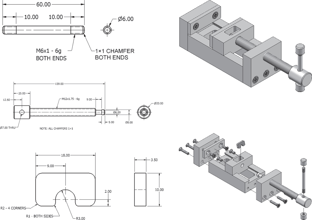
Figure P6-23
Create an assembly drawing.
Create a presentation drawing.
Animate the presentation drawing.
Create an exploded isometric drawing.
Create a parts list.
Project 6-24: Inches
Given the assembly drawing shown in Figure P6-24:


Figure P6-24
Create an assembly drawing.
Create a presentation drawing.
Animate the presentation drawing.
Create an exploded isometric drawing.
Create a parts list.