
Chapter 35
Power Supply Overview and Specifications
35.1 Power Supplies
Whatever you do with electronics, you are going to need power to accomplish it. It will be useful to understand the basics of power supplies, as you are nearly guaranteed to deal with them at some point in your career.
35.1.1 It’s All About the Voltage, Baby!
Most devices today want to keep the voltage constant. This means that current can vary as needed. In the world of power, particularly as it relates to the ubiquitous IC, it often seems that you never have the exact voltage you want.
A huge number of products run off of 120 VAC out of a wall socket. Another huge group runs off of batteries that are charged from those wall sockets, and another significant number runs off of batteries that you can buy by the caseload at any supermart. Just ask yourself, how many batteries did you buy last Christmas?
The problem is that most ICs these days want 5, 3.3, or even 1.5V DC. This is nowhere near 120V, and definitely not AC! Enter the power supply. They come in two flavors, linear and switcher.
35.1.2 Linear Power Supplies
AC rules! It is everywhere. It may seem like the world runs on batteries these days, but AC still has the majority foothold. Back when Edison and Tesla argued over what type of electrical power distribution we should have, I’ll bet they had no idea of the type of integration that would occur in the world of electricity over the next 100 years.
One thing they did know about was the transformer. The basis of the transformer is AC current. Put AC into one side of the transformer and, depending on the ratio of windings, you get AC out the other side. So, put 120 VAC into a 10-to-1 ratio transformer and you will get 12 VAC out (minus heat losses due to the resistance of the windings).
The basic transformer is a very simple design. It is coils of wires on hunks of metal. That makes it robust. A transformer is a perfectly acceptable way to change the voltage of an AC signal. Transformers are used to jack the voltage way up to minimize losses over long wires, and then they are used again to bring the voltage back down to something safer to bring into your house.
They further knock the voltage down again in millions of products, but at that point they still output an AC signal. However, most of our chips want a DC signal, so what happens next?
It goes through a rectifier. There are two commonly used options, a bridge rectifier as shown in Figure 35.1, and a center tap rectifier, as shown in Figure 35.2. Note how this uses two fewer diodes and another wire to the transformer, yet the rectified output is the same.

Figure 35.1 Bridge rectifier

Figure 35.2 Center tap bridge rectifier
The output at this point is still too “bumpy” to be of much use to our sensitive DC circuits. The next step is to add a large filter capacitor to smooth out the bumps, as seen in Figure 35.3.
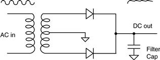
Figure 35.3 Center tap bridge rectifier with cap filter
Here you need to understand the principle of output impedance. Every power supply has it. The more current you pull out of the circuit, the bigger issue the output impedance is. Remember that Ohm’s Law says that, as current increases through an impedance, the voltage drop across it increases. This means that the voltage at the output will drop as load increases. To further complicate things, due to the rectifier in this circuit you will see an increased ripple voltage on the output as load increases. So there are two important things affecting the voltage on the output of this circuit: the voltage going into it (which on most AC circuits can vary 10% or more) and the amount of current being drawn, increasing the voltage drop and the voltage ripple.
This is important to know as we feed this into the next part of the circuit, called a regulator. The regulator is a part that adjusts its output to maintain a constant voltage in the face of a changing load and a changing input voltage.
A linear regulator typically has a voltage reference (like a zener diode) inside it running on a small current that isn’t disrupted by the load. It uses this reference and a negative feedback loop to control a transistor or other part inside to maintain a constant voltage at the output. This gets you to the nice DC voltage that your IC wants. The whole circuit from the wall looks something like that shown in Figure 35.4.

Figure 35.4 Typical linear regulated power supply
There are a couple of important things to know about linear regulators. They have a minimum input voltage. If the input voltage falls below this rating due to circumstances described above, the output will fall out of regulation. If this happens you can get ripple on the power supply to your chip. If it is small enough, you may not ever notice it, but if you have some high-gain circuits picking up AC noise, check out the power supply for problems first.
The other often-overlooked important spec is the power rating of the regulator. A regulator can only handle so much power, even with a heat sink. The power being dissipated by the regulator is the current times the voltage drop across the regulator, not the voltage at the output!
There are many other specs you should review in the data sheet, but these are the most important and often overlooked. Check them first. You can use linear regulators in any DC in, DC out situation. They will do very well in most cases and, to top that, hey are very simple and robust circuits. Use them whenever you can. There is nothing wrong with this technology in certain applications, but if you need more efficiency, or maybe less heat, you should consider a switcher.
35.1.3 Switcher
A type of regulator and power supply rapidly gaining footholds over the older, linear designs is called a switcher. As implied by the name, it regulates power to a load by switching current (or voltage) on and off. For this writing we will focus on the current method. (Don’t forget, however, that current and voltage are invariably linked as Ohm proved so well.) The secret to these supplies is the inductor and the secret to understanding an inductor for me is to think in terms of current. In the same way a capacitor wants to keep voltage across it constant, an inductor wants to keep the current flowing through it constant as well.
35.1.3.1 DC is What We Start With
Switching power supplies are DC-to-DC converters. Even those that have an AC input create a DC bus, using a rectifier circuit before implementing a switcher. You will see switchers replacing just the regulator in the circuit above working off of a DC bus voltage that has already been stepped down by a transformer. You will also see switchers that use rectified voltage right off the AC line and drop and regulate all in one step from 120V down to 5V.
The most basic current-switching supply I know of is the buck converter. A buck converter will knock a DC voltage from a higher level to a lower level. The following diagram shows the heart of a buck circuit.
First identify four main parts: the inductor, the switch, the diode, and the load.

Figure 35.5 Basic switching buck converter
35.1.3.2 Flip the Switch
Let’s start with the load and work our way backward. To begin with, switching supplies like to have a load. Without a load, funny things can happen, but more on that later. What the load wants (in most cases) is a constant voltage. If I remember Ohm’s Law correctly, one can control the voltage across a resistor (i.e., load) by controlling the current through it, so let’s consider the flow of current in this circuit. We will begin with the switch closed. With the switch closed, current will flow through the inductor into the load. The current will rise based on the time constant of the inductor and the impedance of the load. Since the current rises, so does the voltage across the load. Assume now that we have a circuit that is monitoring the voltage across the load, and as soon as it gets too high it opens the switch.
Now what happens? First, remember this fact. Just like a capacitor resists a change in voltage, an inductor resists a change in current. When the switch opens, the inductor tries to keep the current flowing. If there is nowhere for it to go, you will see a large voltage develop across the inductor as the magnetic field collapses. In fact, at time = 0 the value of this voltage is infinite or undefined, whichever suits you. That doesn’t happen in this case due to the diode and the load.
The current flows into the load, and the reason it does so is because of the diode. Consider it this way—current wants to keep flowing out of the inductor and into the other side of the inductor. Without the diode there would not be a path for this current to follow. However, with the diode, this current is pushed through the load. So now the switch is open, and current is still flowing into the load. This current starts out at the same level it was when the switch opened (an inductor wants to keep current the same, remember!) and it decays from there. As the current falls, so does the voltage. Of course we still have a circuit monitoring the voltage across the load, and as soon as it gets too low, it closes the switch again.
Voila, the process starts all over. There are two important things I noticed once the pieces fell into place in my head. The first is this control circuit I just described can be implemented with a simple comparator and a little hysteresis. Of course, that would lead to the frequency of the switcher being determined by the value of the inductor and the impedance of the load. That may or may not be a desirable trait. The other thing I realized was that when you first turned it on, the circuit would want to slam the switch shut and keep it there for a long time while current builds up in the circuit. Are you beginning to see why switchers need a load?
Luckily, others much smarter than I have dealt with these problems already. That is why you hear terms like “soft start” and “built in PWM” when you start studying switching supplies.
35.1.3.3 Some Final Thoughts on Switchers
Since designing switching supplies, getting them stable and dealing with the inductor specs can be a bit demanding, technical and tedious, all sorts of industry help has sprung up in the effort of various companies trying to get you to use their parts. You will find design guides and even web design platforms out there to help you build a switcher for your design, and I highly suggest you take advantage of them.
These days you will often find all the brains, switching components and feedback parts in one cute little package, making the design nicely compact and small. You can make switchers that boost voltage as well as the buck versions, and some that even go both ways, but ultimately they rely on the fact that the inductor wants to keep current flow the same. We will save the more in-depth review for another book on another day.
The best thing about switching supplies is the fact you can get by with relatively little copper and attain very high efficiency (meaning less heat). The reason for this is that the decay rate of the current in the inductor depends on the size of it, but if you switch it faster, the average current and thus the average voltage is still maintained. So you can get by with much less copper, especially for larger current draws at low voltages. The efficiency is good because much less power is spent heating the copper in the small inductor than in an equivalent transformer design. However, all this comes at a price. Switchers are known for their high-frequency noise that has disrupted many a sensitive analog design. But who cares about analog any more, right?
Thumb Rules
• Make sure the lowest dip on the ripple voltage doesn’t go below minimum input of the regulator.
• Check your supply at ±15% of the AC input signal.
• Linear regulators dissipate heat/power based on the current times the voltage from input to output (i.e., across it).
• Switchers exploit the fact that inductors want to keep current flowing even when the switch is open.
• Switchers are more efficient and create less heat but generally are more finicky to setup.
• Linear supplies are very quiet when it comes to EMI.
35.2 Specifications
The technical and commercial considerations that apply to a power supply can add up to a formidable list. Such a list might run as shown in Table 35.1.
Table 35.1 Power supply specifications
| • input parameters: | minimum and maximum voltage maximum allowable input current, surge and continuous frequency range, for AC supplies permissible waveform distortion and interference generation |
| • efficiency: | |
| • output parameters: | |
| • abnormal conditions: | output power divided by input power, over the entire range of load and line conditions |
| • mechanical parameters: | minimum and maximum voltage(s) minimum and maximum load current(s) maximum allowable ripple and noise load and line regulation transient response |
| • safety approval requirements | performance under output overload performance under transient input conditions such as spikes, surges, dips and interruptions performance on turn-on and turn-off: soft start, power-down interrupts |
| • cost and availability requirements. | size and weight thermal and environmental requirements input and output connectors screening |
35.3 Off-the-Shelf or Roll Your Own
The first rule of power supply design is: do not design one yourself if you can buy it off the shelf. There are many specialist power supply manufacturers who will be only too pleased to sell you one of their standard units or, if this doesn’t fit the bill, to offer you a custom version.
The advantages of using a standard unit are that it saves a considerable amount of design and testing time, the resources for which may not be available in a small company with short timescales. This advantage extends into production—you are buying a completed and tested unit. Also your supplier should be able to offer a unit which is already known to meet safety and EMC regulations, which can be a very substantial hidden bonus.
35.3.1 Costs
The major disadvantage will be unit cost, which will probably though not necessarily be more than the cost of an in-house designed and built power supply. The supplier must, after all, be able to make a profit. The exact economics depend very much on the eventual quantity of products that will be built; for lower volumes of a standard unit it will be cheaper to buy off the shelf, for high volumes or a custom-designed unit it may be cheaper to design your own. It may also be that a standard unit won’t fulfill your requirements, though it is often worth bending the requirements by judicious circuit redesign until they match. For instance, the vast majority of standard units offer voltages of 3.3V or 5V (for logic) and ±12V or 15V (for analog and interface). Life is much easier if you can design your circuit around these voltages.
A graph of unit costs versus power rating for a selection of readily-available single output standard units is shown in Figure 35.6. Typically, you can budget for £1 per watt in the 50 to 200W range. There is little cost difference between linear and switch-mode types. On the assumption that this has convinced you to roll your own, the next chapter will examine the specification parameters from the standpoint of design.

Figure 35.6 Prince vs. power rating for standard power supplies