
Chapter 4. Extending Arduino
- Software libraries
- The Arduino core and standard libraries
- Contributed libraries
- Hardware shields
- Some common shields
In previous chapters, you looked at the digital input and output and analog input functionality of the Arduino, and you constructed a few projects based on this functionality, including a reactometer and a pentatonic keyboard. But the Arduino is capable of much more, and you can also extend its functionality by using software libraries or hardware shields. In this chapter you’re going to learn different ways of connecting the Arduino to other devices or equipment.
For example, if you were building an obstacle-avoidance robot that could detect objects in its path and maneuver around them, the Arduino would be an obvious choice. There are software libraries and hardware shields readily available that can enable the Arduino to drive motors, connect to infrared or ultrasonic sensors that detect objects, and communicate over Wi-Fi.
Let’s get started by learning about software libraries.
4.1. Extending the Arduino with libraries
In the software world, a library is a piece of software that provides some sort of functionality, such as writing text to an LCD screen or calculating your position from a GPS navigation system. Software libraries work in the same way as conventional reference libraries: you request information and then use it within your project. Imagine you’re working on a research project: you take a reference book out of a library and use the parts you need in your project. It’s exactly the same with a software library.
In the Arduino world, a library is a piece of software that you include in your sketch and that provides some form of functionality. For example, there’s a LiquidCrystal library that, when included in your sketch, will give you the ability to communicate simply with some LCD displays. A library is often used many times across many projects.
Some libraries can be used on their own, whereas others need to be used with additional electronic components, often in the form of shields. We’ll cover the use of shields later in this chapter.
There are three different types of Arduino libraries: core, standard, and contributed. We’ll start with the built-in core library.
4.2. Core library
The core library is built into the main Arduino IDE and is central to what makes the Arduino such a great device for both beginners and more experienced users. The core library hides much of the complexity traditionally involved when working with a microcontroller. Members of the Arduino development team, who were involved with teaching students how to use microcontrollers in their projects, recognized that the downfall of many traditional microcontrollers was the difficulty of programming them. They looked at what actions many of their students wanted to perform with a microcontroller and, based on this, designed a core library that makes these actions easy to perform.
Most projects read data in (input) or write data out (output), and the core library makes these common tasks simple to execute. For example, to read the value of a digital pin, you just need to use the easily remembered digitalRead. Other common functions you’ve already used include digitalWrite and analogRead.
In your last project, the pentatonic keyboard, you used another core function, Tone, to output sound to a loudspeaker, and you used the Serial functions to send code output to the serial monitor:
- Serial.begin(9600)
- Serial.print("Hello World")
In later chapters, you’ll come across other core functions, but for now we’re going to look at the standard libraries that are included as part of the Arduino IDE.
4.3. Standard libraries
When you downloaded and installed the Arduino IDE, some standard libraries were included with the installation. The standard libraries are ones that the Arduino development team thinks will be needed by many people in their own projects. They aren’t included by default in your projects like the core library, because the Arduino has limited resources; automatically including the libraries would be a waste of these resources, leaving little room for code in your own sketches.
To use the standard libraries, you have to explicitly include them in your sketches. To do so, you need to add an include statement at the top of your sketch. For example, if you wanted to include the LiquidCrystal library, which is used to display data on an LCD screen, you would place the following at the top of your sketch:
#include <LiquidCrystal.h>
Note
The name of the library is bounded by angle brackets: < and >. Also, the line doesn’t end with a semicolon (;) as is usual.
The standard libraries are described in the following sections:
- ArduinoTestSuite library
- EEPROM library
- SD library
- Ethernet library
- Firmata library
- LiquidCrystal library
- Servo library
- Stepper library
- SPI library
- Wire library
- SoftwareSerial library
We’ll also revisit some of these libraries in later chapters, where we’ll go into much more detail about them.
4.3.1. Test-driven development with ArduinoTestSuite
The ways that code and sketches are written and developed are always evolving, and hopefully improving. One of the more recent innovations is a software process called test-driven development (TDD).
In TDD, a software project is split into small pieces, and before you write any of the pieces of code, you first write tests, with each test checking a particular function. When you write the code, it’s run against the tests and must pass for that piece to work correctly; if it doesn’t pass, you correct any errors and test the code again. When the piece of code passes its tests, you repeat the process for the next piece of code. This continues until the project is finished. If a change is made to a piece of code at a later date, you can run the tests to make sure everything still functions correctly and that the change has not caused other areas of the program to malfunction.
The ArduinoTestSuite library is the first step in bringing this methodology to Arduino development. It’s a relatively new library, but it’s seen as being essential to future development on Arduino. The ArduinoTestSuite library provides standard methods and functions that can be used to test your sketches before uploading them to the Arduino. This ensures that your code sketch works as intended before using it with expensive real-world devices that may be harmed if used incorrectly.
The library is still in active development, but it currently has tests for the processes listed in table 4.1.
Table 4.1. The tests available in the ArduinoTestSuite library
|
Test |
Description |
|---|---|
| ATS_begin | Initiates the beginning of the test process |
| ATS_end | Completes the test process |
| ATS_Test_DigitalPin | Tests the given digital pin |
| ATS_Test_PWM | Tests PWM output |
| ATS_Test_AnalogInput | Tests analog input |
| ATS_Test_EEPROM | Tests the EEPROM |
| ATS_TestSerialLoopBack | Tests the RX and TX of serial ports |
| ATS_GetFreeMemory | Returns the amount of free memory available on the Arduino |
The idea of incorporating software testing as part of Arduino development is new, but it will likely become more important as development of the IDE continues and functionality increases.
4.3.2. Storing values using EEPROM
Electrically Erasable Programmable Read-Only Memory (EEPROM) is a type of memory that retains its values even when a microcontroller is turned off. The amount of EEPROM on an Arduino board is dependent on the microcontroller at its core. Table 4.2 lists the amount of EEPROM memory available on the microcontrollers used on different Arduino boards.
Table 4.2. EEPROM memory on microcontrollers used on Arduino boards
|
Microcontroller |
EEPROM memory (bytes) |
|---|---|
| ATMega8 and ATMega168 | 512 |
| ATMega328 | 1,024 |
| ATMega1280 and ATMega2560 | 4,096 |
Note
The Arduino Uno is based on an ATMega328; it has 1,024 bytes of EEPROM memory.
The EEPROM library gives sketches access to the Arduino’s EEPROM and provides two functions, read and write, as shown in table 4.3.
Table 4.3. The functions available in the EEPROM library
|
Function |
Description |
|---|---|
| read | Reads the value of a byte stored at a location in EEPROM |
| write | Writes a value to a location in EEPROM |
Note
Any data written to the EEPROM remains there even when the Arduino is switched off.
A good use of the EEPROM library would be to store settings in between Arduino restarts—for example, constants that might be used by an LCD interface, data in a counting application, or the highest score in a game. If you want to store more data than this, it might be time to think about using SD cards.
4.3.3. Storing more data with SD
The Arduino doesn’t have a convenient way of storing data, apart from the onboard EEPROM, which is only suitable for storing configuration settings and tiny amounts of data. To store the data logged from that GPS guided rocket project you’ve been working on, you’re going to need to look elsewhere. Luckily, others have already paved the way, and there are a number of shields available that can use SD or SDHC memory cards, which are commonly used in digital cameras for storing pictures.
One of the advantages of using SD or SDHC cards is that they’re readily available in a variety of memory sizes, and they’re relatively cheap, with prices starting at just a few dollars. Table 4.4 shows the typical differences between SD and the higher-capacity SDHC cards.
Table 4.4. Key differences between SD and SDHC memory cards
|
SD |
SDHC |
|
|---|---|---|
| Capacity | 0–2 GB | 4 GB–32 GB |
| File storage system | FAT16 or FAT32 | FAT32 |
William Greiman wrote an Arduino library called SdFat that supports the FAT16 and FAT32 filesystems on SD cards. The SdFat library provides a comprehensive range of functions: creating and deleting files and directories, and performing basic formatting.
The Arduino team realized that many users would find it difficult to use the SdFat library, so they built a wrapper around it, making it friendlier to use by exposing only a subset of its functions.
Note
The SdFat library uses a lot of program memory, which limits the size of your sketches, so it’s recommended that you use it with an Arduino that has at least an ATMega328P processor.
When included in your sketch, the SD library provides a range of basic functions, as listed in table 4.5, enabling the Arduino to interact with SD cards.
Table 4.5. The functions provided by the SD library
|
Class |
Function |
Description |
|---|---|---|
| SD | begin | Initializes the SD library and card |
| exists | Tests existence of file or directory on the card | |
| mkdir | Creates directory on the card | |
| rmdir | Deletes directory on the card | |
| remove | Deletes file from the card | |
| open | Opens file on the card | |
| File | available | Checks if any bytes are available to read from a file |
| close | Closes file and makes sure data written to it is saved on the card. | |
| seek | Seeks a position in the file | |
| position | Returns current position within the file | |
| size | Returns size of the file | |
| Prints data to already open file | ||
| println | Prints data to file and appends newline | |
| write | Writes data to the file | |
| read | Reads a byte from the file |
Note
The SD library can only use the 8.3 filesystem—an eight-character filename and a three-character extension, separated by a period. You can’t use long descriptive filenames or names with spaces in them.
Arduino uses a serial peripheral interface bus (SPI; more about this in section 4.3.9) to communicate with the SD card, which uses digital pins 11, 12, and 13 on a standard Arduino and 50, 51, and 52 on a Mega. In addition, pin 10 is commonly used to select the card device on a standard Arduino and pin 53 on the Mega; an alternative pin can be used by specifying it in the call to SD.begin.
Note
Before an SD card can be used by the Arduino, it must first be properly formatted as either FAT16 or FAT32 using your computer and a card reader.
A microSD shield is available from SparkFun Electronics, as shown in figure 4.1.
Figure 4.1. The microSD shield from SparkFun Electronics

A range of shields is also available with onboard microSD card connectors, including the latest official Ethernet shield and data logging shields available from SparkFun Electronics and Adafruit Industries.
4.3.4. Get connected with Ethernet
An increasing number of people want their projects to be remotely accessible so that they can share their data or results over a home network, or so that the project can be controlled over an internet connection. Sending status messages via Twitter is a favorite goal in many projects, which requires the Arduino to tweet the results of some form of input. An early example came from a baker whose oven was connected to an Arduino: it tweeted a message to his customers whenever a fresh batch of bread was ready for sale.
The Ethernet library simplifies the TCP/IP stack, making it easier to get an Arduino to communicate over the internet or home network. The library is designed to work with WIZnet W5100-based boards. The latest official Arduino Ethernet board also has an onboard microSD card connector that’s great for data-logging applications. You could use the Arduino to take readings in a remote location and display the readings on a basic web page as well as log them to a microSD card that could be retrieved and further analyzed at a later date.
The Ethernet library is very extensive and allows the Arduino to be set up as either a server, which receives connections from clients, or as a client, which connects to servers. Table 4.6 shows some of these functions.
Table 4.6. Some of the functions provided by the Ethernet library
|
Class |
Function |
Description |
|---|---|---|
| Ethernet | begin | Initializes library and network settings |
| localIP | Returns local IP address | |
| dnsServerIP | Returns DNS server address | |
| Server | Server | Creates server |
| begin | Starts to listen for connections | |
| available | Retrieves a client that has data available to read | |
| write | Writes data to clients; data is byte or char | |
| Writes data to clients; data can be byte, char, int, long, or string | ||
| println | Writes data to clients, followed by a newline | |
| Client | Client | Creates client |
| connected | Returns true if client is connected to server | |
| Connect | Connects to IP address and port specified | |
| write | Writes data to a connected server | |
| Writes data to server; data can be byte, char, int, long, or string | ||
| println | Writes data to server, followed by a newline | |
| available | Returns number of bytes to be read from server | |
| read | Reads next byte from server | |
| flush | Discards bytes waiting to be read by client | |
| stop | Disconnects from the server |
As you can see in table 4.6, the Ethernet library is rich in functionality and is under active development as we head to a more connected world.
4.3.5. Serial communication with Firmata
Firmata is a communication protocol that allows a host computer to use software to control a microcontroller. The Firmata library provides the serial communication protocols for communicating with the software on a host computer.
Using Firmata, a host computer can control devices attached to the Arduino, such as servos, motors, and LEDs. You can have your own glorious Technicolor light-and-sound show controlled by a host PC that sends commands to one or more Arduinos.
Table 4.7 shows some typical Firmata functions.
Table 4.7. Typical Firmata functions
|
Method |
Description |
|
|---|---|---|
| Common | begin | Initializes Firmata library |
| printVersion | Sends protocol version to host computer | |
| setFirmwareVersion | Sets firmware version | |
| Sending messages | sendAnalog | Sends an analog message |
| sendDigitalPortPair | Sends digital pin value | |
| sendsysex | Sends a command with an array of bytes | |
| sendString | Sends a string to the host PC | |
| Receiving messages | available | Checks buffer for incoming messages |
| processInput | Processes incoming messages | |
| attach | Attaches a function to an incoming message type | |
| detach | Detaches a function from an incoming message type |
The Firmata protocol is evolving all the time; visit http://firmata.org/wiki/ to get the latest updates and information. We’ll take a more detailed look at Firmata in chapter 13.
4.3.6. Displaying data using the LiquidCrystal library
You’ve seen in previous chapters how the Arduino can display information on the Arduino IDE’s built-in serial monitor, but what about when the Arduino isn’t connected to a host computer? It can be handy to use a small 16-character-by-2-row (16 x 2) LCD to display information to your project users. Most of these small LCDs are based on a Hitachi HD44780 or compatible chip.
This requirement is so common that we’ve devoted a whole chapter—chapter 7—to just dealing with LCD displays. You’ll learn how to show your project users GPS data, status messages, and other cool and useful stuff.
Central to all this is the LiquidCrystal library that’s used to drive the display. Table 4.8 lists some of the functions available in the library.
Table 4.8. Some LiquidCrystal library functions
|
Function |
Description |
|---|---|
| begin | Sets the dimensions of the LCD screen in rows and columns |
| LiquidCrystal | Initializes the library and sets up the pins used to communicate with the LCD |
| Prints data to the LCD | |
| clear | Clears the LCD screen |
| setCursor | Positions the cursor on the LCD screen |
You’ll learn more about LCD displays in chapter 7.
4.3.7. Controlling a servo motor
Servo motors are commonly used in the radio-control world to accurately control movement in models, such as the flaps on a model airplane or the rudder on a model boat. They’re ideal for projects needing accurate movement, such as obstacle-avoidance robots that scan an ultrasonic sensor from side to side looking for objects to avoid.
You’ll be looking at servo motors in much greater detail in the next chapter; for now let’s look at some of the main features of the Servo library. The Servo library allows the Arduino to control up to 12 servo motors on a standard Arduino, and a whopping 48 on the Mega. Table 4.9 shows the main functions provided by the Servo library.
Table 4.9. The main functions provided by the Servo library
|
Function |
Description |
|---|---|
| attach | Attaches servo to a pin. |
| attached | Checks servo attached to pin. |
| detach | Detaches servo from pin. |
| read | Reads angle of servo. |
| write | Writes shaft angle to servo—between 0 and 180 on a normal servo. On a continuous rotation servo, sets the speed of rotation. |
| writeMicroseconds | Writes value to the servo in microseconds, to set the angle of the shaft. |
Note
Using the Servo library disables analogWrite on the PWM pins 9 and 10 for a standard Arduino. On the Mega, using more than 12 servos will disable analogWrite on pins 11 and 12.
Another type of motor is a stepper motor, and there’s another library for driving them.
4.3.8. Turning a stepper motor
A stepper motor rotates its motor shaft in steps; the specification of a stepper motor is often given in steps, so a motor with a specification of 200 steps would take 200 steps to rotate one revolution.
Sometimes the specification is given in degrees; this can easily be converted to steps by dividing one revolution, which is 360 degrees, by the number of degrees given in the specification. For a stepper motor with a specification of 1.5 degrees, you would calculate the number of steps per revolution as follows:
360 degrees / 1.5 degrees per step = 240 steps
Stepper motors are therefore a great way of controlling devices precisely.
The Stepper library gives the Arduino control over both unipolar and bipolar types of stepper motors. Using the library, you can set the speed of rotation of the motor, the number of steps to take, and the motor direction. Table 4.10 lists the main functions provided by the Stepper library.
Table 4.10. Main functions provided by the Stepper library
|
Function |
Description |
|---|---|
| Stepper | Initializes Stepper library and sets the number of steps per revolution |
| setSpeed | Sets speed at which motor should turn, in rotations per minute (RPM) |
| step | Steps the motor the number of steps specified; positive numbers rotate one way, negative numbers the other |
We’ll cover the Stepper library in much greater detail in chapter 5, where we’ll also look at the different types of stepper motors available.
4.3.9. Communicating with SPI peripherals
Serial peripheral interface bus (SPI), sometimes called four-wire bus, is a synchronous serial communications protocol used for communicating over short distances with external peripherals. SPI can be used to communicate with a variety of peripherals or sensors, including temperature sensors, pressure sensors, analog-to-digital converters, touch screens, videogame controllers, and onscreen displays. You’ve already seen that the Arduino uses SPI to communicate with SD cards.
The protocol has a single master, the Arduino, and one or more slave devices. Because of the lack of a formal standard, there’s some variation in how individual manufacturers apply SPI to their own devices, so you’ll probably need to resort to a data sheet if you want to connect to a particular peripheral.
The protocol uses four wires, three of which are common to each device, and one that’s a slave select. Their designations are shown in table 4.11.
Table 4.11. Four wire designations for SPI on the Arduino
|
Designation |
Description |
Arduino pin |
Mega pin |
|---|---|---|---|
| MISO | Master In Slave Out, sending data to master | 12 | 50 |
| MOSI | Master Out Slave In, sending data to slave | 11 | 51 |
| SCK | Serial clock | 13 | 52 |
| SS | Slave select | Normally 10 | 53 |
Each slave has a slave select wire but shares the other three wires. Digital pin 10 (53 on the Mega) is normally used as the slave select line, but others can be set during setup. The Arduino Ethernet shield uses pin 4 to connect to the onboard SD connector and pin 10 to connect to the Ethernet controller.
The SPI library provides functions to interact with SPI peripherals, as shown in table 4.12.
Table 4.12. SPI functions
|
Description |
|
|---|---|
| begin | Initializes the SPI bus and sets the MOSI and SCK pins low and the SS pin high |
| end | Disables SPI bus |
| setBitOrder | Sets the order in which bits are loaded into the bus |
| setClockDivider | Sets the SPI clock divider as a division of the system clock |
| setDataMode | Sets SPI data mode |
| transfer | Transfers one byte over the bus |
Let’s have a closer look at a couple of those functions:
- setBitOrder—This sets the order in which data is sent to the bus. The choices are either Most Significant Bit (MSB) or Least Significant Bit (LSB). The peripheral data sheet should give you this information.
- setClockDivider—This governs the speed that the SPI bus runs at, as a divisor of the system clock. The default divider setting is 4, which reduces the speed of the SPI bus to a quarter of the system clock; other divisors are 2, 8, 16, 32, 64, and 128.
- setDataMode—This controls the mode of transmission of data between the slave peripheral and the master. There are three main transmission modes, and these depend on whether data is shifted in or out on the rising or falling edge of the clock pulse, which is called clock phase. The other consideration is whether the clock is idle when set high or low; this is the clock polarity.
Table 4.13 summarizes the setDataMode modes.
Table 4.13. The setDataMode modes dependent on clock phase and clock polarity.
|
Mode |
Clock polarity (CPOL) |
Clock phase (CPHA) |
|---|---|---|
| 0 | 0 | 0 |
| 1 | 0 | 1 |
| 2 | 1 | 0 |
| 3 | 1 | 1 |
Although this looks complicated, by making good use of the data sheet and carefully following each step for setting up the SPI bus, you should be able to communicate with SPI peripherals with confidence.
4.3.10. Communicating with the two-wire interface
I2C, commonly known as two-wire interface (TWI), is used to communicate with a wide range of low-speed devices and components, including real-time clocks. It’s perfect for logging applications, LCD displays, ultrasonic rangers for distance measurements, and digital potentiometers whose resistance can be read or set remotely. Interestingly, I2C is also used in Nintendo game controllers, the Wii Motion Plus, and Wii Nunchuks. We’ll look at interfacing with those in chapter 9.
Only two pins are needed for the I2C bus interface. Table 4.14 identifies these for the standard Arduino and Mega.
Table 4.14. Pin designations on the standard Arduino and the Mega for I2C
|
Standard Arduino |
Mega |
|
|---|---|---|
| SDA data line | Analog input pin 4 | Digital pin 20 |
| SCL clock line | Analog input pin 5 | Digital pin 21 |
With the Wire library, the Arduino can act as either a master or slave device. In most cases, the Arduino will be the master device and will interact with one or more slave devices on the I2C bus; each slave device has a unique address to distinguish it on the bus network. It’s possible to string devices together, up to a maximum of 112.
The Arduino can also be set up as a slave device, and when in this mode, it interacts with a master device.
Table 4.15 lists the main functions of the Wire library.
Table 4.15. List of main Wire library functions
|
Function |
Description |
|---|---|
| begin | Initializes the Wire library and joins I2C bus either as master or slave. |
| requestFrom | Requests data from slave to master. |
| beginTransmission | Prepares to start transmission of data. |
| send | Sends data from slave to master or queues bytes for transmission from master to slave. |
| endTransmission | Ends transmission (begun by beginTransmission) of data to a slave, and sends the bytes queued by send. |
| available | Returns number of bytes available for retrieval with receive. Should be called on the master device after a call to requestFrom or on a slave inside the onReceive handler. |
| receive | Retrieves byte transmitted by slave device after a call to requestFrom or from a master to a slave. |
| onReceive | Registers function to call when the slave receives a transmission from the master. |
| onRequest | Registers function to be called when the master requests data from the slave device. |
We’ll take a more detailed look at using the Wire library in chapter 9.
4.3.11. Get more serial ports with SoftwareSerial
Many projects require at least one serial port. GPS devices send position and status messages serially, and some LCDs can be interfaced to a serial controller. A serial port is made up of just two connections: one RX for receiving messages, and one TX for transmitting or sending messages.
The beauty of a serial port is its simplicity. At one time every computer had a serial port; in fact, the original Arduino used a serial port for connecting to the computer, and even through the connection is now made by USB, it still emulates a serial port and appears to the host computer as a serial port.
The Arduino Uno and Duemilanove have one hardware serial port connected to digital pins 0 and 1, but if your project needs to connect to more serial devices than this—for example, to both a GPS and a serial LCD controller—you have a choice. You can either purchase the more powerful Arduino Mega, which has four dedicated hardware serial ports, or use the SoftwareSerial library that’s distributed with the Arduino IDE.
The original SoftwareSerial library could only provide one software serial port in addition to the hardware port, and it was limited to a speed of 9600 baud. These limitations were addressed by Mikal Hart with his NewSoftSerial library. Realizing the advantages this library had, the Arduino development team renamed it and incorporated it as a replacement for the existing SoftwareSerial library in mid-2011. Table 4.16 shows the functions provided by the new library.
Table 4.16. The functions of the SoftwareSerial library
|
Function |
Description |
|---|---|
| begin | Activates port and sets baud rate |
| available | Switches to that port |
| isListening | Returns current active port |
| listen | Listens to port and makes active |
| end | Terminates port |
| read | Reads data from port |
| write | Writes data to port |
The updated library can create multiple instances of software serial ports, which can communicate at up to speeds of 115,000 baud. But all this additional functionality comes at a price, because the Arduino can only listen or receive data on one software serial port at a time, although it can transmit data on any port. When using the library with more than one software port, you’ll need to think carefully about your sketch structure and the order in which data will be received.
Let’s consider an example: You want to connect to both a GPS and a serially connected thermometer using software serial ports. GPS devices tend to send their data in bursts at intervals of a second, so your sketch could start by listening to the software serial port connected to the GPS, and after it has received the burst of data, switch to listening to the other port and process its data before switching back to the port connected to the GPS. Here’s a sketch demonstrating how this would work in practice.
Listing 4.1. Using the SoftwareSerial library with two ports

As you can see, the SoftwareSerial library is a great addition to your toolbox, but you must be careful when using it with more than one software serial port.
This concludes our roundup of the standard libraries. But what if you want to work with other devices or peripherals that aren’t covered by the standard libraries? There’s a good chance that someone has written a library that you can use in your project. In the next section, we’re going to look at how to use these user-contributed libraries.
4.4. Contributed libraries
Contributed libraries are libraries that are contributed by users of the Arduino but that aren’t distributed as standard with the Arduino IDE. You’ll find many of these libraries listed on the main Arduino website.
Some of these libraries are extensions to the standard libraries, offering a few more functions, and over time, if these additions are deemed suitable, the development team may add them to the standard libraries or even to the core library. Other contributed libraries are designed to work with particular devices, such as game controllers—you’ll see one of these used in chapter 9.
So how do you add a contributed library to your project? Because these libraries aren’t distributed with the IDE, you need to perform a couple of additional steps before you can use one of them.
4.4.1. Installing a new library
Adding a contributed library to the Arduino IDE requires a few simple steps:
- Download the library, usually a zip file.
- Install it into the Arduino IDE by copying the unzipped files to your default sketch directory libraries folder. If the libraries folder doesn’t exist, you’ll need to create it.
- If the IDE is already started, you’ll need to restart it. The library should now be available to your code.
- Add the library to your sketch by selecting Sketch > Import Library from the menu, as shown in figure 4.2, where a couple of contributed libraries are displayed.
Figure 4.2. The contributed libraries available to a sketch after installation

Note
Once a library is added to the IDE, it will be available for use with future projects, just like the standard libraries are.
Once a library has been imported to a sketch, all its functions are available to the sketch.
This concludes our look at Arduino software libraries for now. In the chapters ahead, we’ll come back to some of them, and we’ll also introduce more contributed libraries to help you get even more functionality out of the Arduino. In this section, you’ve seen how the use of software libraries can extend the functionality of the Arduino, allowing it to interface with many devices and peripherals, thus allowing you to quickly produce complex projects. In the next section we’re going to look at another common way to extend the Arduino: using hardware shields.
4.5. Expanding the Arduino with shields
Shields are another great way to add functionality to the Arduino. Want to control that robot by Wi-Fi? Get a Wi-Fi shield! Want to use your television as a display? Get the TellyMate shield! Want to program games like pong? Buy a game shield! These and a host of other shields are available and let you connect the Arduino to a wide range of hardware and peripherals.
Arduino shields are pluggable hardware boards that connect to the headers on an Arduino. Many of the shields have their own headers, so they can be stacked on top of each other. To get the most out of a shield, you’ll often need additional libraries, and these are usually downloadable from the manufacturer of the shield, ensuring that you have the latest version.
Shields are a great way of expanding the Arduino, and they can come fully assembled or as a kit. If you’re unsure of your soldering skills, it might be a good time to learn. Check to see if there’s a local electronics hobby group or hacker space where someone can teach you. Alternatively, you can often purchase shields fully assembled and tested, although this will be more expensive.
You can even make your own shields from scratch. Many shield manufacturers have fully embraced the open hardware movement and provide the necessary files and drawings to make your own printed circuit boards (PCBs).
In later chapters, you’ll make extensive use of shields in your projects because they’re such a quick and neat way of extending the Arduino. But first, let’s learn about some of the common shields that are available.
4.5.1. Common shields
These are some common shields that are generally available:
- Motor shields
- Ethernet shields
- Wi-Fi shields
- Prototyping shields
Let’s start with motor shields.
Motor shields
Motor shields are usually suitable for controlling small DC motors. They’re sufficiently powerful to power small robots or vehicles, and they can also be used with stepper and servo motors.
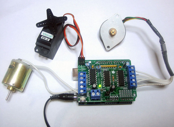
There are a variety of versions available. Adafruit Industries produces a motor shield, shown in figure 4.3, capable of driving two servo motors, two stepper motors, and up to four DC motors. We’ll be making extensive use of this shield in chapter 5, where Arduino goes mobile.
Figure 4.3. A motor shield from adafruit.com
Ethernet
Looking to get your project connected to the internet, tweeting status messages, or responding to remote commands? We’ve already looked at the standard Ethernet library, and this is the hardware to go with it.
The official Arduino Ethernet shield, shown in figure 4.4, is based on the WIZnet W500 with its full TCP/IP stack. If you plan to purchase the official Arduino version new, make sure you purchase the latest version, which has an onboard microSD socket. Adafruit Industries produces an alternative version that’s also compatible with the library. A cheaper option is to purchase a shield based on the ENC28J60 SPI Ethernet controller version, but this isn’t directly supported by the Arduino team and has less functionality, though it may be enough for your project.
Figure 4.4. The official Arduino Ethernet shield

Wi-Fi
Everything seems to be going wireless nowadays, and the Arduino is no exception. Wi-Fi gives you wireless control, which is ideal for remote-operated robots, as well as connecting to the internet.
There are a couple of different shields available that provide Wi-Fi functionality. The WiFly shield from SparkFun is shown in figure 4.5.
Figure 4.5. The WiFly shield from SparkFun

Prototyping shields
Bare or prototyping shields are excellent for use with your own projects. There are a few different versions available; some have an onboard breadboard, and others have a prototyping area you can solder components to. Figure 4.6 shows an example of a prototyping shield available from adafruit.com.
Figure 4.6. A prototyping shield from adafruit.com

Note
Shields that are available as kits aren’t always provided with headers, so you may need to purchase these separately.
4.5.2. Gotchas: will it work with my Arduino?
When using shields on a project—particularly if using more than one—care must be taken as to which pins are used by an individual shield. There’s a great website, www.shieldlist.org, that has a comprehensive list of shields and which pins they use. It’s worth checking the site for compatibility between shields that you want to use in your project.
A further consideration is the components on a shield. Some components are very tall and may interfere with any shields stacked on them.
You must also determine whether a shield is compatible with your Arduino. Some don’t work with the Arduino Mega or require modifications to work with it. Others require a minimum of a 328 processor and won’t work with the older 168 processor found in Diecimila and an early version of the Duemilanove Arduino.
4.6. Summary
In this chapter, we’ve looked at ways of expanding the functionality of the basic Arduino by using software libraries and hardware shields to interface the Arduino with a wide range of hardware and peripherals.
We started off by looking at software libraries, including the core library and those provided as standard with the Arduino IDE. We then looked at the vast range of contributed libraries and how they can be used in your projects.
In the second part of the chapter we looked at hardware shields, which are another excellent way of expanding the Arduino. We looked at some of the common shields and discussed some considerations you need to be aware of, mainly when using more than one shield or using the Arduino Mega.
In the next chapter, we’ll use both libraries and shields to add motor functionality to your Arduino projects.