
Chapter 8. Communications
- Creating an Ethernet web server to query data from your Arduino
- Tweeting messages from your Arduino to Twitter
- Wi-Fi network and Bluetooth communication with the Arduino
- Data logging onto an SD card and to the internet using the Cosm service
- Communicating with other devices over the Serial Peripheral Interface (SPI) protocol
In the previous chapter, we investigated how you can receive visual feedback from the Arduino by communicating with LCD screens. Imagine if you could display information from the Arduino on an external screen, and also send it out over the internet for the world to see! What if you could control your Arduino remotely?
Getting your Arduino on the internet and remotely talking to your computer are two of the many communication channels possible with the Arduino. We’ll look at communicating with your Arduino via Ethernet, Wi-Fi, Bluetooth, and SPI.
As many of your projects will involve communicating over the internet, let’s dive right in and look at how to communicate with the Arduino over a computer network.
8.1. Ethernet
One of the most powerful communication channels available on the Arduino is Ethernet. Ethernet is a standardized networking facility that allows all kinds of devices to communicate with each other by sending and receiving streams of data (called packets or frames).
Ethernet is extremely fast and robust, transmitting the data back and forth across the network without error. Each device on the network gets a unique identifier called an IP address, which allows the devices to communicate via different internet protocols.
The Arduino makes setting up internet communication easy using the Ethernet Shield and the Ethernet library, but before we discuss the library and shield, let’s take a look at a few key networking concepts. If you’re already familiar with networking concepts, it still may be worth reviewing the terminology and technologies in table 8.1.
Table 8.1. Key Ethernet terms and concepts
|
Term |
Description |
|---|---|
| Ethernet | Ethernet is a standardized networking technology that describes a way for computers and other devices to send information back and forth over a wired network. |
| Protocol | Protocols are established communication languages that allow devices to talk to one another. In order for two devices to communicate, they both must be speaking the same language, or protocol. For example, the Hypertext Transfer Protocol (HTTP) is a common protocol that you’ll use to set up your Arduino as a web server. Using HTTP, you’ll establish a language that allows the Arduino web server to understand messages and requests from web clients such as a computer’s web browser. |
| MAC address | A Media Access Control (MAC) address is a unique identifier assigned to Ethernet and other networking devices. The MAC address allows the devices to be uniquely identified in order to communicate with other devices. Your Arduino shield will come with a sticker giving it a unique MAC address. |
| TCP/IP | Transmission Control Protocol (TCP) and Internet Protocol (IP) are internet protocols that pass messages over the global internet (the home of the “world wide web” we all know and love). |
| IP address | An IP address is a unique address that devices and servers use to identify themselves over the global internet. For example, when you go to a website, such as manning.com, the internet uses the Directory Name Service (DNS) to translate http://google.com/ to a numeric IP address, such as 209.85.148.139. |
| Local IP address | Local IP addresses are similar to regular IP addresses, but they’re used specifically to communicate between computers and devices on a local network. For example, when you set up a network at home, each computer on the network is assigned a local IP address to communicate with the router and other computers on the network. |
Although networking and Ethernet are complex topics that can take many years to fully understand, table 8.1 presents the fundamental terms you’ll need to know in order to understand the rest of the chapter.
Now that you’ve reviewed the table, let’s move on to the Ethernet library and see what it does.
8.1.1. The Ethernet library
The Ethernet library comes bundled with the Arduino IDE and allows you to configure your Arduino and Ethernet Shield to communicate with the outside world. You can configure up to four concurrent servers and clients (total). You set up the server such that it first accepts incoming connections from clients and then sends and receives data. In contrast, a client makes outgoing connections to the server first and then can send data to and receive it from the server.
More on this soon, but for now take a look at table 8.2, which provides an overview of the functions available in the Ethernet library.
Table 8.2. Overview of the Ethernet, Server, and Client class functions in the Ethernet library
|
Function |
Description |
|---|---|
| Ethernet.begin(mac) Ethernet.begin(mac, ip) Ethernet.begin(mac, ip, gateway) Ethernet.begin(mac, ip, gateway, subnet) |
Initializes the library, supplying the MAC address of the shield, and automatically configures your IP using DHCP. Optionally, supplies a manual IP address, gateway (typically your router’s IP address), and subnet mask (default is 255.255.255.0, which tells the shield how to interpret IP addresses). |
| Server(port) | Creates a server to listen on a specific port. |
| Server.begin() | Starts the server listening for messages. |
| Server.available() | Returns a client if a client has data ready. |
| Server.write() | Sends data to all connected clients. |
| Server.print() | Prints data to all clients. Numbers print as a sequence of ASCII digits; for example, 123 becomes three characters, ‘1’, ‘2’, and ‘3’. |
| Server.println() | Same as Server.print() but with a newline character at the end of each message. |
| Client(ip, port) | Creates a client that can connect to the specified IP address and port. |
| Client.connected() | Returns whether or not the client is connected. If the connection is closed and some data is still unread, this will still return true. |
| Client.connect() | Starts the connection. |
| Client.write() | Writes data to the server. |
| Client.print() | Prints data to the server. Numbers print as a sequence of ASCII digits; for example, 123 becomes three characters, ‘1’, ‘2’, and ‘3’. |
| Client.println() | Same as Client.print() but with a newline character at the end of each message. |
| Client.available() | Returns the number of bytes available to be read (the number of bytes sent from the server). |
| Client.read() | Reads the next byte received from the server. |
| Client.flush() | Flushes any bytes that have been written to the client but have not yet been read. |
| Client.stop() | Disconnects from the server. |
In addition to the Ethernet, Server, and Client classes, the Ethernet library also includes useful general-purpose User Datagram Protocol (UDP) networking classes to broadcast information over a network. When a server or client isn’t required, the UDP class is what you’ll use to broadcast data to or receive it from the Arduino. Table 8.3 details the functions in the UDP class.
Table 8.3. Overview of main UDP class functions in the Ethernet library
|
Function |
Description |
|---|---|
| EthernetUDP.begin(port) | Initializes UDP object and specifies listening port. |
| EthernetUDP.read(packetBuffer, MaxSize) | Reads UDP packets from a buffer. |
| EthernetUDP.write(message) | Sends a message to the remote connection. |
| EthernetUDP.beginPacket(ip, port) | Must be called before sending a message, specifying the destination IP and port. |
| EthernetUDP.endPacket() | Must be called after the message is sent to end the message. |
| EthernetUDP.parsePacket() | Checks to see if there’s a message to be read. |
| EthernetUDP.available() | Returns how much data has been received and is available to be read. |
Now that we’ve covered the functions and classes in the Ethernet library, let’s take a look at the Ethernet Shield. You’ll use the shield to extend the hardware functionality of your Arduino so you can plug into a wired Ethernet network.
8.1.2. Ethernet Shield with SD data card
The original Ethernet Shield was a milestone for the Arduino platform, enabling projects to communicate over networks and over the internet. Powered by the WIZnet W5100 Ethernet chip, it provides a network (IP) stack with both TCP and UDP, over a 10/100 Mb Ethernet connection. The shield has a standard RJ45 Ethernet jack allowing it to plug and play with your modem, router, or other standard devices.
The newer, widely-available Ethernet Shield improves upon the original by adding a microSD card slot on the shield itself. This means you can read and store files on your shield (by plugging in an SD card and using the SD library). But it’s important to note that the W5100 chip and the SD card both communicate with the Arduino using the SPI bus (more information on SPI can be found in section 8.6). On most Arduino boards, this is on pins 11, 12, and 13, and on the Mega it’s pins 50, 51, and 52. On both boards, pin 10 is used to select the W5100 and pin 4 to select the SD card. This is important because it means you can’t use these pins as general-purpose I/O pins.
Note
Because the W5100 chip and the SD card both use SPI, only one can be active at a time. To use the SD card, you only need to set pin 4 as an output and set it HIGH; for the W5100, set digital pin 10 as an output and set it HIGH. Also, the hardware SS pin (pin 10 on most Arduino boards and 53 on the Mega) might not be used, but it must be left as an output (default) for the SD and Ethernet libraries and SPI interface to work.
8.2. Arduino web server
With the basics of Ethernet, the Ethernet library, and the Ethernet Shield under your belt, you’re ready to start your first Ethernet-powered project. For this project you’re going to build an Arduino web server, a call-and-response system that can accept requests from clients and in turn send back data (as illustrated in figure 8.1). To do this, you’ll use the Server and Client classes included in the Ethernet library.
Figure 8.1. Overview of Arduino web server communication

8.2.1. Setting up the server
To set up the server, you’ll need a few pieces of information.
First, you’ll need to know the MAC address of the Arduino Ethernet Shield, which should be printed on a sticker on the shield. In the code you’ll use for the server, you’ll store the MAC address in a byte array, like so:
byte mac[] = { 0xDE, 0xAD, 0xBE, 0xEF, 0xFE, 0xED };
Remember, this is the unique hardware address that’s used to talk directly to your shield over Ethernet.
If you have an older Ethernet Shield without the sticker, or you’ve lost your sticker, you can use the MAC address from the preceding example. The important thing is that if you have more than one device on the network, they all must have unique MAC addresses.
Next, you’ll need your IP address. Since Arduino 1.0, the built-in Ethernet library supports Dynamic Host Configuration Protocol (DHCP), enabling Arduino to automatically discover your IP address. This will automatically configure your IP address whether you’re connected directly to your modem or to a networked router, as long as they have DHCP enabled (which is typically the case).
You’ll only need to find out the IP of your router and manually specify an IP address for your Arduino Ethernet Shield if your network isn’t using DHCP, or if you’re using a version of Arduino prior to 1.0. There are different techniques for doing so, depending on your setup.
If your Arduino is connected directly to your modem, the IP address will be supplied by your internet service provider (ISP). To find your IP address in this case, it may be easiest to connect a computer to your modem—there are many websites that can report your IP address. (A quick internet search for the term IP lookup should get you an address, or you can try www.whatismyip.com/.) Note that your IP address is automatically assigned by your ISP and may change from time to time.
If your Arduino is connected to your network via a router, you’ll have to assign an unused local network IP address to your Ethernet Shield instead. To manually assign your Arduino an unused local IP, you’ll need to know a bit more about your network’s configuration. You can discover your router’s IP address by using a web service via a computer connected to the network as described previously. Alternatively, you can go into your router’s administration control panel. Normally, you can do this by opening your web browser and going to the default router IP, typically http://192.168.1.1 for Linksys and many other brands, or http://10.0.0.1. If your router’s IP address is 192.168.1.1, you’ll want to give your Arduino an IP address of 192.168.1.x, where x is any number from 1 to 255. Each computer or network device on your network will have a unique 192.168.1.x address, where the final number identifies the device on the network, so make sure your Arduino Ethernet Shield doesn’t conflict with other devices. The same rules apply if your router is using another addressing pattern, such as the 10.0.0.x address.
If you do have to manually supply your IP address, you’ll do so in an IPAddress object, like this:
IPAddress manualIP(192, 168, 1, 2);
The numbers in the preceding code line should be the IP address you want to set.
Finally, if you’re on a network and using the router to connect to the internet, you may also need to specify your router as the gateway. Create a byte array and store the router’s IP address to be used as the gateway. Here’s an example:
byte gateway[] = { 192, 168, 1, 1};
Now that you know the IP configuration for your network, let’s move on to the code.
8.2.2. Sketch for creating a web server
The following listing puts everything we’ve discussed into practice by creating a web server on the Arduino. The server will be given the task of getting online (or onto a local network), accepting incoming client connections (sent via a web browser), and responding with a custom message. This listing is a great template for starting almost any server-based application.
Listing 8.1. Arduino web server


First, you initialize the server on HTTP port 80 ![]() . Once it’s initialized, you can try to connect the Arduino to the Ethernet network using DHCP
. Once it’s initialized, you can try to connect the Arduino to the Ethernet network using DHCP ![]() , or using a manual IP address if DHCP fails
, or using a manual IP address if DHCP fails ![]() . Then you start the server and start polling in the main loop
. Then you start the server and start polling in the main loop ![]() .
.
Once you’ve connected to a client and the data is received, a newline character delineates the end of a message, and you send
a response back to the client ![]() .
.
8.2.3. Upload and test
Carefully copy the code from listing 8.1 into the Arduino IDE, and you’re ready to upload the sketch to your Arduino.
Once you’ve uploaded the code and it’s running, you can connect to the Arduino server remotely by opening up any web browser and going to http://your_arduinos_network_ip_address. Your web browser (the client) will send a connection request out to your Arduino web server, which will respond by sending back the message, “Hi! I am your Arduino web server in Action!” That’s it.
Want to see real-time data? Try connecting a potentiometer or sensor up to analog input 0, and change the line
client.println("Hi! I am your Arduino web server in Action!");
to this:
client.println(analogRead(0));
We hope this has worked without a hitch, but if you aren’t getting a response, please read the following brief troubleshooting section.
8.2.4. Troubleshooting
If you can’t establish a connection, the first thing to double-check is your IP settings.
If you’re positive that your settings are correct and you’re on a home network, it’s possible that you need to set up port forwarding on your router. Setting up port forwarding will tell your router to forward incoming messages specifically to your Arduino. Setting up port forwarding isn’t difficult, but you’ll have to do it through your router’s configuration. See your router’s documentation for more information on how to set up forwarding to your Arduino’s IP address, and you should be good to go.
8.3. Tweet tweet: talking to Twitter
Creating a web server to communicate with the outside world is great, but another powerful option is to hook into other online services. One service that’s great to tap into is Twitter.
The way Twitter works is simple. Once you have a Twitter account, you can broadcast tweets (messages) up to 140 characters long to the entire Twitter network. People can subscribe to your feed and automatically receive your tweet updates. Not only that, Twitter plays nicely with other services, meaning that you can automatically have your tweets post to your Facebook account as well.
Wouldn’t it be great if you could set up a Twitter feed to automatically update when various things happen on your Arduino? You can. In this section, you’ll learn how to set up your Arduino and Ethernet Shield to automatically send tweets to a Twitter feed when you press a button connected to your Arduino.
8.3.1. Of Twitter and tokens
If you don’t already have a Twitter account, or you want to set up a new one for this project, go to www.twitter.com and create one now.
Next, you need to get a special “token” that will authorize the Arduino to send messages to your Twitter account. This token enables a middleware web service to mediate between your Arduino and Twitter. It’s possible to communicate directly with Twitter, but going through a middleware service is useful because it’ll prevent your code from breaking if or when Twitter updates its protocol and authorization. It also helps make the Twitter library more lightweight and saves memory space, which can be precious on the Arduino.
To get the token, go to http://arduino-tweet.appspot.com/ and click on the “Step 1: Get a token to post a message using OAuth” link.
Once your account is set up, it’s time to take a closer look at the libraries you’ll be using.
8.3.2. Libraries and functions
To communicate with Twitter, you’ll need to install the Twitter library from www.arduino.cc/playground/Code/TwitterLibrary. Once you’ve downloaded it, place the library in your sketchbook or libraries folder.
Table 8.4 describes the Twitter library’s functions.
Table 8.4. Overview of the Twitter library’s functions
|
Function |
Description |
|---|---|
| Twitter(string token) | Constructor takes in the authorization token. |
| bool post(const char *message) | Begins posting a message. Returns true if connection to Twitter is established, false if there’s an error. |
| bool checkStatus(Print *debug) | Checks if the posting request is still running (can omit passing in the debug argument if no output is required). |
| int status() | Returns the HTTP status code response from Twitter, such as 200–OK. The status is only available after posting the message has completed and checkStatus() returns false. |
| int wait(Print *debug) | Waits until posting the message is done. Returns the HTTP status code response from Twitter. |
8.3.3. Circuit diagram and connecting the hardware
Now that your Twitter and Arduino IDE are set up, let’s build a simple circuit to send tweets whenever a user presses a button. Solder together the following simple button circuit, or assemble it on a breadboard.
Connect one leg of a push button to 5V and the other to GND through a 10k ohm pull-down resistor. Also connect that same leg (the one connected to ground) to digital input 2, as shown in figure 8.2.
Figure 8.2. Simple button-tweeting circuit

8.3.4. Sketch for the Twitter button-press tweeter
Once you have the button wired up and the Ethernet Shield plugged in to your Arduino, copy the following code into the Arduino IDE and you’re ready to go. Be sure to read the comments in the code carefully to make sure it’s configured correctly for your network settings. If you need clarification on any of the networking concepts or terms, refer to section 8.1.
Listing 8.2. Twitter button-press tweeter


First, try to connect the Arduino to the Ethernet network using DHCP ![]() , or with a manual IP address if DHCP fails
, or with a manual IP address if DHCP fails ![]() . Once it’s connected, start your serial connection so you can print debug messages to the console
. Once it’s connected, start your serial connection so you can print debug messages to the console ![]() .
.
With everything connected, use the sendTweet function to format and send Tweets properly ![]() . Then check for button presses and send tweets
. Then check for button presses and send tweets ![]() .
.
8.3.5. Upload and test
Once you’re sure everything is correct, compile and upload the code to your Arduino. You’re now ready to broadcast your button presses to Twitter. Check that you have the code running on your Arduino and that your Arduino is connected to the internet via an Ethernet cable, and you should be all set.
Press the button on your Arduino and log in to Twitter.com. You should see your last tweet, which says “Times button pressed: 1,” as shown in figure 8.3. Each time you press the button, you’ll see a new tweet pop up, incrementing the number of times the button has been pressed. Nice job.
Figure 8.3. Screenshot of a Twitter button tweet

Note
Twitter blocks the same post from being sent consecutively within a short amount of time. In listing 8.2, the message changes each time the button is pressed (the number of times increments), so this isn’t a problem. In most cases where messages are sent periodically or where they vary, this won’t be a problem, but it’s something to keep in mind.
As you can imagine, you can broadcast many other useful things besides a simple button press. Perhaps a sensor is triggered when the front door opens or closes at your house. Perhaps you tweet real-time data and visualize the information in your gallery installation—we’re only scratching the surface here.
8.4. Wi-Fi
The Ethernet Shield will get your Arduino online in no time, but surely there will be times when being wireless would be useful. Perhaps you need to retrieve real-time data from a roaming rover-bot you’ve made, or your project needs to get online but isn’t near a wired router or connection. Enter the official Arduino Wifi Shield, an elegant solution that will get your Arduino up and running on Wi-Fi networks.
Note
If you own the SparkFun WiFly (a popular alternative to the official Arduino Wifi Shield), or need to use it in your project for other reasons, we adapted this section to work with the WiFly module. A web link to the adapted section can be found in appendix E.
8.4.1. Arduino Wifi Shield
The Arduino Wifi Shield will enable your Arduino to connect to any 802.11b/g wireless network. It uses the HDG104 wireless LAN system in package (SiP) from H&D Wireless, which provides an optimized, low-power wireless connection. This Wifi Shield is capable of communicating with both UDP and TCP, and using it is as easy as mounting it on top of your Arduino and writing a few lines of code using the WiFi library. The Wifi Shield’s header pins also provide female connection points along the top, which makes it easy to retain access to your Arduino’s pins, or to stack on additional shields.
In addition to supporting the 802.11b/g specification, the Wifi Shield supports both WEP and WPA2 personal encrypted networks. Once your sketch is uploaded and the Arduino is configured, your Arduino can be disconnected from the computer, powered externally, and serve two-way communications from anywhere within range of a wireless router.
Not only that, the Wifi Shield also provides an onboard microSD slot that can be used with both the Arduino Uno and Mega via the easy-to-use SD library. This is great if you want to store information and then send it out over the network, and in section 8.7 of this chapter you’ll see exactly how to use the SD library.
The Arduino Wifi Shield and SD card reader communicate using the SPI bus (which is discussed further in section 8.6), which has a few important details regarding the use of your general I/O pins.
On the Arduino Uno, SPI communication is supported on digital pins 11, 12, and 13, and on the Mega, pins 50, 51, and 52. On both boards, pin 10 is used to select the HDG104 and pin 4 is used for the SD card reader. The hardware SS pin on the Mega (digital pin 53) isn’t used by either the SD card reader or the HDG104, although it must be configured as an output for the SPI interface to work properly. Digital pin 7 is used as a handshake pin between the Wifi Shield and the Arduino, and it’s vital that none of the mentioned pins be used for any I/O.
Lastly, because the shield’s Wi-Fi chip (HDG104) and SD card reader both use the SPI bus, only one can be active at any given time. If both are being used, the SD and WiFi libraries automatically handle this for you, but if you’re using just one, you must explicitly deselect the other (if you aren’t using an SD card reader, you must manually deselect it), as you’ll see in the example code.
The Wifi Shield has been well thought out and provides several useful features beyond the Wi-Fi connection. It’s completely open source and has a Micro-USB port to support firmware updates in the future. It also has a series of status LEDs that report useful information, such as connection status (LINK/green), whether there are communication errors (ERROR/red), and whether data is being transmitted or received (DATA/blue).
Using your Wifi Shield with Older Arduino Boards?
The Arduino Wifi Shield uses the IOREF pin available on newer Arduinos to sense the reference voltage for the I/O pins of the board it’s connected to. This means that if you’re using an Arduino Uno or Mega2560 earlier than REV3, you must connect a jumper wire between IOREF and 3.3V (as detailed in figure 8.4).
Figure 8.4. Overview of pins used by Wifi Shield.

8.4.2. WiFi library and functions
To begin using your Wifi Shield, you’ll use the WiFi library. Arduino plans to include the library with a future release of the IDE, but currently (version 1.0.1 or earlier) the library must be downloaded and installed from the Arduino website.
The WiFi library handles all of the low-level networking communication for you and also provides support for many of the commands and functionality provided by the Wifi Shield.
At this point, it would be good to familiarize yourself with table 8.5, which provides an overview of the main functions you’ll use from the WiFi library.
Once you’ve reviewed table 8.5, you’re ready to move on to the example project, where you’ll be sending out gestural sensor data over a wireless network.
Table 8.5. Overview of the WiFi, WiFiServer, and WiFiClient library functions
|
Description |
|
|---|---|
| WiFi.begin() WiFi.begin(char[] ssid) WiFi.begin(char[] ssid, char[] pass) WiFi.begin(char[] ssid, int keyIndex, char[]key) |
Initializes the WiFi library and begins communication with the device. You can join any open network, or provide the network’s SSID, password for WPA encrypted networks, or keyIndex and key for WEP encrypted networks (WEP encryption can store up to four different keys, so a keyIndex must be supplied). This function returns the Wi-Fi status. |
| WiFi.disconnect() | Disconnects from the current network. |
| WiFi.SSID() | Gets the SSID of the current network and returns a String. |
| WiFi.BSSID(bssid) | Gets the MAC address of the router connected to and stores it in the 6-byte array passed in as an argument (for example, byte bssid[6]) |
| WiFi.RSSI() | Returns the signal strength of the connection as a Long. |
| WiFi.encryptionType() WiFi.encryptionType(wifiAccessPoint) |
Returns the type of encryption of the current (or specified) access point. Returns as a byte value, where TKIP (WPA) = 2, WEP = 5, CCMP (WPA) = 4, NONE = 7, AUTO = 8. |
| WiFi.scanNetworks() | Returns the number of discovered networks as a byte. |
| WiFi.getSocket() | Returns the first socket available. |
| WiFi.macAddress() | Returns a 6-byte array representing the Wifi Shield’s MAC address. |
| WiFi.localIP() | Returns the IP address of the shield (as an IPAddress). |
| WiFi.subnetMask() | Returns the subnet mask of the shield (as an IPAddress). |
| WiFi.gatewayIP() | Returns the gateway IP address (as an IPAddress). |
| WiFiServer(int port) | Creates a server to listen on a specific port. |
| WiFiServer.begin() | Starts the server listening for messages. |
| WiFiServer.available() | Returns a client if a client has data ready. |
| WiFiServer.write(data) | Sends data to all connected clients (either byte or char). |
| WiFiServer.print() | Prints data to all clients. Numbers print as a sequence of ASCII digits; for example, 123 becomes three characters, ‘1’, ‘2’, and ‘3’. |
| WiFiServer.println() | Same as WiFiServer.print() but with a newline character at the end of each message. |
| WiFiClient() | Creates a client that can connect to the specified IP address and port defined in connect(). |
| WiFiClient.connected() | Returns whether or not the client is connected. If the connection is closed and some data is still unread, this will still return true. |
| WiFiClient.connect(ip, port) WiFiClient.connect(URL, port) |
Starts the connection using the IP address and port specified. Will resolve the IP address from a URL. |
| WiFiClient.write(data) | Writes data to the server (byte or char). |
| WiFiClient.print() | Prints data to the client. Numbers print as a sequence of ASCII digits; for example, 123 becomes three characters, ‘1’, ‘2’, and ‘3’. |
| WiFiClient.println() | Same as WiFiClient.print() but with a newline character at the end of each message. |
| WiFiClient.available() | Returns the number of bytes available to be read (the number of bytes sent from the server). |
| WiFiClient.read() | Reads the next byte received from the server. |
| WiFiClient.flush() | Flushes any bytes that have been written to the client but have not yet been read. |
| WiFiClient.stop() | Disconnects from the server. |
8.4.3. Gestures: wireless accelerometers
In this example, you’re going to use a Wi-Fi-powered Arduino to send sensor data from an accelerometer wirelessly over a network. Accelerometers are fantastic sensors allowing all kinds of exciting gestural interactions. Perhaps you’re interested in investigating new game-playing scenarios (as made popular by the Nintendo Wii), or putting accelerometers on a dancer’s body to use their motion to control live visuals and sound, or using accelerometers in assistive aids for the physically impaired. As you can see, practical uses for wireless accelerometers abound, and we’re sure you can think of more.
In this example, you’ll need the following:
- An Arduino
- The Arduino Wifi Shield
- At least one accelerometer (such as the ADXL335)
You’ll use the Processing language to create a server via which you can stream and parse the data from your wireless accelerometers.
8.4.4. Connecting the hardware
Connecting the Wifi Shield should be as simple as plugging it in directly on top of your Arduino. The steps for wiring up the accelerometer to your Arduino will differ depending on the particular model you’re using.
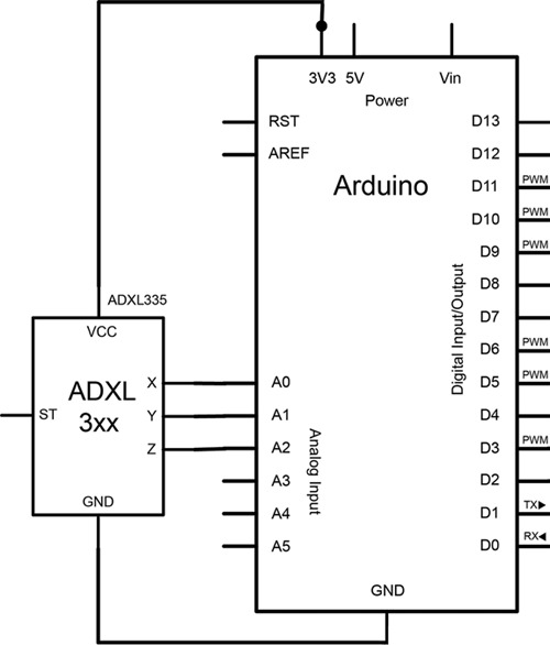
If you’re using the ADXL335 tri-axis accelerometer, which provides an independent analog output for each of its axes (x,y,z), please refer to figure 8.5 when making your connections. If you’re using another accelerometer model, the connections may be similar or may use PWM pins instead of the analog inputs. Refer to your model’s datasheet and documentation for the proper connections if you’re using another type of accelerometer.
Figure 8.5. Connecting the ADXL335 analog accelerometer to the Arduino
With the Wifi Shield and accelerometer connected, you’re ready to rock and roll.
8.4.5. Sketch for Bluetooth communication
Let’s use the WiFi library to get your Arduino to send the accelerometer data wirelessly to a server running on your computer. Wait—server on your computer? How do you do that?
You’re going to use a programming environment called “Processing,” so if you don’t already have it on your computer, now would be a good time to go to processing.org and download the latest version. If you haven’t used Processing before, don’t worry; the code in listing 8.4 will look familiar to the code you’ve written before.
But first, let’s get the Arduino side of things moving along with the following code.
Listing 8.3. Arduino accelerometer client


After importing the necessary libraries and supplying a few network and server details, you must create a WiFiClient object ![]() . Then, in the setup routine you initialize the serial library for debugging
. Then, in the setup routine you initialize the serial library for debugging ![]() , before attempting to open a network connection using a method you create called connectToNetwork
, before attempting to open a network connection using a method you create called connectToNetwork ![]() . You attempt to join the Wi-Fi network using WiFi.begin
. You attempt to join the Wi-Fi network using WiFi.begin ![]() , and wait ten seconds to connect
, and wait ten seconds to connect ![]() . Next you enter the main loop, and if you successfully connected to the network
. Next you enter the main loop, and if you successfully connected to the network ![]() , but are not yet connected to the server
, but are not yet connected to the server ![]() , you attempt to connect to the server. If you’re already connected to the server, you read and send the current accelerometer
values
, you attempt to connect to the server. If you’re already connected to the server, you read and send the current accelerometer
values ![]() .
.
In the next listing we jump into Processing and create a server that will accept incoming connections from clients (the Arduino) and display the messages it’s receiving on the screen. For a bit more information on Processing, you can take a quick peek at section 13.2 in chapter 13.
Listing 8.4. Processing sketch to request accelerometer data from Arduino server


After you set up the window and font for displaying your data in the setup function, you instantiate the server to start listening
for incoming clients ![]() . The draw function is similar to the main loop in Arduino, and it continuously checks for incoming clients
. The draw function is similar to the main loop in Arduino, and it continuously checks for incoming clients ![]() . If a client connects, you unpack the message (thisClient.readString()), append it with additional information such as the client’s IP address, and display it in your window
. If a client connects, you unpack the message (thisClient.readString()), append it with additional information such as the client’s IP address, and display it in your window ![]() .
.
8.4.6. Upload and test
That’s it. Click the play button on the Processing sketch, and Processing will open a window on your computer screen and the server will start. Upload the Arduino code to your Arduino, and as long as your network is properly configured (your Arduino and computer are on the same Wi-Fi network, and you’ve configured your Arduino with your computer’s IP as the server), you should begin to see the accelerometer values displaying on your Processing program’s window.
If you hunger for more, perhaps a good place to start would be to unpack the individual accelerometer data from the String you received, and visualize the three (x,y,z) axes on your display.
8.5. Bluetooth wireless
Wi-Fi isn’t the only type of wireless communication you can have between the computer and your Arduino. Another viable option is Bluetooth, the wireless technology made popular by cellphone headsets and peripherals.
Bluetooth technology was developed by Ericsson as an open wireless technology that provides an alternative to traditional wired serial communication. Bluetooth is intended for near-field communication, meaning its range and speed are both limited. Nonetheless, it provides enough proximity, speed, resolution, and security for many scenarios and use cases. And because a Bluetooth device manifests itself as a virtual serial port (figure 8.6 shows a MacBook Pro’s internal Bluetooth device as a regular serial device in the Arduino IDE’s device list), sending data from your Arduino over Bluetooth couldn’t be any easier, utilizing the same commands as normal serial communication. This means that whether your sketch sends to the computer via standard serial over USB or via Bluetooth, the code remains the same—and we love this kind of portable code.
Figure 8.6. Screenshot showing how your computer’s Bluetooth chip acts as a serial device

8.5.1. ArduinoBT
The ArduinoBT (pictured in figure 8.7) is an Arduino board with an embedded Bluetooth module for wireless communication. It can run on a minimum of 1.2 volts, making it battery-friendly in wireless scenarios. Compared to other models with similar ATmega chips, the ArduinoBT has two additional analog inputs (8 total), but they don’t have header pins soldered in. In order to use the extra inputs, you can either solder directly to the pads, or solder on two additional header pins (recommended).
Figure 8.7. ArduinoBT, a Bluetoothenabled Arduino board

Note
Don’t use pin 7; it’s connected to the reset pin and should only be used for resetting the module.
8.5.2. Adding Bluetooth
If you don’t have the ArduinoBT or your project requires one of the other models in the Arduino line, you’re in good company. There are many Bluetooth add-ons, such as the BlueSMiRF line (recommended) available at SparkFun.
The BlueSMiRF line connects to your Arduino’s RX/TX serial lines, so wiring it up couldn’t be easier. As described in figure 8.8, simply connect the VCC pin on the BlueSMiRF to 5V on your Arduino. Next, wire GND on the BlueSMiRF module to GND on your Arduino. Lastly, wire the communication lines by connecting RX on the BlueSMiRF module to TX on the Arduino, and TX on the BlueSMiRF module to RX on the Arduino.
Figure 8.8. Connecting the SparkFun BlueSMiRF Silver to an Arduino

Note
As the Bluetooth module takes control of the Arduino RX/TX lines, it must be disconnected when you’re uploading sketches to the Arduino over USB.
8.5.3. Establishing a Bluetooth connection
The first step in Bluetooth communication is pairing your Bluetooth-enabled Arduino to your computer. During this step, your computer will create a virtual serial port between your computer and your Arduino over the Bluetooth connection. Many laptops today come with Bluetooth built in, but if your computer doesn’t, you can easily buy a Bluetooth USB module for under $50—a great gift for any hobbyist or part-time Arduino hacker.
The process of pairing your ArduinoBT and computer varies depending on your operating system but the settings are the same. You’re going to look for a device called ARDUINOBT if you’re using an ArduinoBT or another self-describing name if you’re using a third-party Bluetooth module, and connect using the passphrase 1234. That’s it.
You should see your computer and Bluetooth-powered Arduino connected, and now you can return to the Arduino IDE as normal.
8.5.4. Sketch for Bluetooth communication
Writing code for our Bluetooth-powered Arduino is no different than for communicating over USB. Remember, the Bluetooth module shows up as a virtual serial port, so you can utilize the exact same Serial.print commands you’re already familiar with.
The one catch to keep in mind is that the communication between the Arduino sketch and your Bluetooth module needs to be at the same baud rate—for the ArduinoBT, this will be 115,200 baud. In your setup function you need to make sure you set the correct baud rate when opening up the serial connection, such as Serial.begin(115200).
The code in listing 8.5 doesn’t do anything fancy, but it shows what a simple Bluetooth sketch looks like. It properly configures the baud rate and then wirelessly broadcasts a random number every second over Bluetooth serial. The exciting thing is that getting this code going with your current project is as simple as modifying the print commands in the sketch to send out the readings from whatever sensor your project calls for.
Listing 8.5. Bluetooth test sketch
void setup(){
  Serial.begin(115200);
}

void loop(){
  Serial.print(random(1024));
  delay(1000);
}
Note
If your messages don’t seem to be sending correctly, double-check your baud rate. Some Bluetooth modules may communicate at 9,600 or other speeds.
Congratulations, you’ve now covered the most common ways to communicate with your Arduino over a network and wirelessly. The topic of communications, however, is broad, and remotely talking to your Arduino isn’t the only type of communication possible. In the following section you’ll learn about a nifty communication channel called serial peripheral interface; it’s a powerful way to have your Arduino communicate with other devices.
8.6. Serial peripheral interface (SPI)
Serial peripheral interface (SPI) is a synchronous data protocol that enables multiple microcontrollers and peripheral devices to quickly communicate with one another over short distances. It follows a master-slave metaphor, where one device (usually a microcontroller) becomes the master, controlling all connected slave peripherals.
Normally SPI communicates over three channels:
- MISO—Master input, slave output
- MOSI—Master output, slave input
- SCK—Serial clock
The three lines’ functions are relatively simple: MISO is the line for sending data from a slave to the master, MOSI is the line for sending data from the master to slave devices, and SCK (sometimes written SCLK or Clock) is a clock pulse that synchronizes the data transmission.
There’s also a fourth slave select (SS) pin on each peripheral that you can use to select which device you wish to talk to. Setting the SS pin LOW tells the device to communicate with the master, while setting it HIGH tells it to ignore the master. By using the SS pin, you can have multiple devices utilizing the same three communication lines, and you can switch between devices one at a time by setting their pins LOW and HIGH respectively. A visual overview of the SPI communication channels is provided in figure 8.9.
Figure 8.9. SPI communication channels

The other great thing about SPI is that because the MISO and MOSI lines are independent, you can use both at the same time (whereas other protocols, such as I2C, use one line for both directions of communication).
Please refer to table 8.6 when making SPI connections to the Arduino.
Table 8.6. Arduino SPI connection overview
|
SPI line |
Arduino pin (non-Mega) |
Arduino Mega |
|---|---|---|
| Slave select or chip select (SS/CS) | 10 | 53 |
| Master out, slave in or serial data in (MOSI/SDI) | 11 | 51 |
| Master in, slave out or serial data out (MISO/SDO) | 12 | 50 |
| Clock pulse (SCK/SCLK) | 13 | 52 |
8.6.1. SPI library
To make things easier, the lovely people at Arduino have created an SPI library so you can get up and running quickly. Table 8.7 lists the library functions you’ll use to get your devices talking over SPI.
Table 8.7. Arduino SPI library functions
|
Function |
Description |
|---|---|
| begin() | Initializes the SPI bus setting SCK, MOSI, and SS to outputs (SCK and MOSI LOW, and SS HIGH) |
| end() | Disables SPI |
| setBitOrder(order) | Sets the order in which bits are shifted into or out of the SPI bus; will either be LSBFIRST (least-significant bit first) or MSBFIRST (most-significant bit first) |
| setClockDivider(amt) | Sets the SPI clock divider relative to the system clock; default is 4 (one quarter the system clock frequency) but can be 2, 4, 8, 16, 32, 64, or 128 |
| byte transfer(val) | Transfers one byte over the SPI bus in both directions; val is the byte to send over the bus, and the function returns the byte read by the bus |
| setDataMode(mode) | Sets the clock mode (polarity and phase): SPI_MODE0, SPI_MODE1, SPI_MODE2, SPI_MODE3 |
Once you familiarize yourself with these functions, you can move on to wiring up a peripheral to your Arduino and communicating between the two over SPI.
8.6.2. SPI devices and digital potentiometers
There are many devices that communicate over SPI, ranging from color LCD screens to magnetometers to controllable RGB LED grids. In fact, the Ethernet Shield and SD card readers discussed earlier all use SPI to communicate with the Arduino. The basic principles of communicating with them are all the same, so to demonstrate basic use of SPI we’re going to use the SPI-based AD5206 digital potentiometer by Analog Devices.
Digital potentiometers are very similar to their analog counterparts we use every day, except that they’re adjusted electronically rather than by hand. The AD5206 digital potentiometer by Analog Devices has six independent pots built into it that you can access, and you can find digital potentiometers in many other configurations as well.
In this example, we’re going to use four of the built-in potentiometers to control the brightness of four LEDs independently, but as you can imagine, the digital potentiometer can be used to control anything that requires a varying voltage.
Let’s get right into it and look at connecting everything up.
8.6.3. Circuit diagram and connecting the hardware
The first thing you’re going to do is look up the data sheet for the digital potentiometer you’re using. SPI communication requires four communication pins (MOSI/SDI, MISO/SDO, SS/CS, and SCK), so you’re going to locate them on the digital potentiometer using the data sheet.
The schematic in figure 8.10 shows the pin layout for the AD5206 digital potentiometer and how it connects to your Arduino and LEDs.
Figure 8.10. Four LEDs controlled by the AD5206 digital potentiometer

First you need to make your main power connections. On the AD5206, connect VDD to 5V on the Arduino and GND to GND. Next, connect VSS on the AD5206 to GND on the Arduino.
With the main power connections made, you can move on to the SPI connections. First, connect the CS pin (chip/slave select) to digital pin 10 on the Arduino. Next you’ll connect the SDI (MOSI) pin to digital pin 11 on the Arduino. Since you’ll be using MOSI, you won’t have a MISO (SDO) pin to connect.
All that remains for SPI communication is the SCK pin, so go ahead and connect SCK to digital pin 13 on the Arduino.
That’s it in terms of chip power and SPI communications. All that’s left are the potentiometers. In figure 8.10, for each of the six potentiometers you’ll see three pins, such as A1, B1, and W1. You can think of these as you do the legs on a regular potentiometer—connect all the A legs to 5V, all the B legs to GND, and all the W legs are your wipers. The W pins are where the varying voltage will come from, so you’ll connect these to the Anode (positive) legs of your LEDs through a resistor (220 ohm should work, but you can calculate this specifically for the LEDs you’re using for optimal brightness). Connect the cathode (negative) legs of the LEDs to GND and you’re done!
Next we’ll look at a simple sketch to dim the LEDs down and brighten them up, and we’ll see the digital potentiometers in action.
8.6.4. Sketch for a digital LED dimmer
With everything connected, it’s time to put the digital potentiometer to work. In the following sketch you’ll loop through the LEDs and adjust their brightness. In doing so, you’ll address the individual LEDs over SPI.
Carefully copy the following listing into the Arduino IDE.
Listing 8.6. SPI digital potentiometer LED dimmer


After importing the SPI library and declaring your variables, you set your slave select pin as an output ![]() . Next, you start SPI communication by calling begin
. Next, you start SPI communication by calling begin ![]() .
.
Setting an LED over SPI is a four-step process, so you create a subroutine called setLed() to perform the four steps each time:
- You set SS LOW to choose the SPI slave to communicate with
 . SPI will then expect two messages: one telling it which register to address, followed by a message setting a value.
- The AD5206 has six registers, and your LEDs are connected to registers 0–3, so you can say SPI.transfer() and pass in the LED number (0–3) you wish to set
 .
.
- Call SPI.transfer() again and pass in a number (0–255) to set the brightness
 . The AD5206 is an 8-bit digital potentiometer, which is why our maximum value for brightness is 255.
- Now that the data is set, you can set SS HIGH and you’re done
 .
.
In the simple loop() function, you iterate through each LED and ramp the brightness up every 20 milliseconds, and then down every 20 milliseconds. Feel free to play around here and come up with other interesting ways to blink your LEDs.
That’s it. Upload your sketch to your Arduino and you should see your LEDs animate by varying the voltage to the LEDs without you having to move your hands, and without using pulse width modulation.
Congratulations, you’ve just tackled one of the intermediate uses of the Arduino. Next we’re going to take a look at another important area where you’ll often use SPI to communicate: data logging.
8.7. Data logging
Sensors are a great way to get readings about something’s current state. But how does that sensor reading change over time, and is that information useful?
Let’s think about music for a moment. Music is a phenomenon that can be thought of as a sequence of events unfolding over a period of time. Each of these musical events can have many different properties such as pitch (how high or low a note is), amplitude (how loud), and timbre (quality), each giving a particular note or sound its “sound.”
In isolation, these notes or events have no musical context. Once played in succession, however, in the context of the composition, different relationships form between the events. Melodies and rhythmic patterns emerge; higher-level structures build from thin air. Even non-musicians with “untrained” ears are great at recognizing these relationships. Even if we can’t express these relationships in musical terms, we possess the ability to embody and feel them. This is because the human brain has long- and short-term memory that’s able to store the relationships of the sounds as they’re played, and even to compare the relationships to the library of sounds and tunes you’ve heard in the past. Our brains can recall and connect the dots for us!
Similarly, if you want to begin to understand the patterns and high-level relationships and information within your sensor data, you must collect the data over a period of time and look for these patterns. In this section, we’re going to look at how you can start logging your data on your Arduino.
8.7.1. Types of memory
In order to log data locally on the Arduino, you need to store it somewhere. Usually this is done with some sort of external memory, like the memory in your computer, cellphone, or thumb drive. The great thing about external memory is that once the memory is stored, it remains even after the device is powered off. This is also true of the EEPROM, Arduino’s built-in memory.
While the EEPROM can retain its memory even when the Arduino is turned off, its space is severely limited. Depending on your Arduino model, you’ll only have between 512 and 4096 bytes of EEPROM memory. This makes the EEPROM good for storing variables and small amounts of data that need to persist between uses of the Arduino, but not very usable in most data-logging scenarios. Because of this, you’ll often turn to other external memory solutions, such as Secure Digital (SD) cards and memory sticks.
8.7.2. SD cards and SD library
SD cards are one of the best ways to store data externally. You can get high-capacity SD cards that should have plenty of space not only for data logging but also hosting other resource files (such as sound files to play or pictures to display), and Arduino comes with an SD library, making reading from and writing to SD cards easy.
Table 8.8 provides an overview of the main SD class functions available in the SD library, but there are many more File class functions enabling you to read from and write to files. Table 8.9 provides a list of the main File class functions, but please refer to the online documentation for a full list of available functions at www.arduino.cc/en/Reference/SD.
Table 8.8. SD library SD class functions
|
Description |
|
|---|---|
| begin(chipSelect) | Initializes the SD library and card, optionally passing in the chip select pin. |
| exists() | Tests if a file or directory is present on the SD card. |
| mkdir("/directory/to/create") rmdir("/directory/to/remove") |
Creates or removes a directory on the card. |
| open("file/to/open", mode) remove("file/to/remove") |
Opens or removes a file at the specified path. When opening, you can specify a mode (FILE_READ or FILE_WRITE) if you want to limit access to only reading, or to read and write to the file. |
Table 8.9. SD library File class functions
|
Function |
Description |
|---|---|
| available() | Checks for bytes available to be read from the file |
| close() | Closes a file, ensuring all data is written to the SD card |
| flush() | Ensures data is physically saved to the SD card; used by close() |
| print() println() write() |
Prints or writes data to the file |
| read() | Reads a byte from the file |
Whether you’re using one of the SD card shields or the SD card reader built into your Arduino Ethernet Shield, communicating with the SD libraries is always the same. If you’re comfortable with the functions we covered previously, you’re more than ready to write a sketch to log some real data.
8.7.3. Sketch for an SD card sensor logger
In this section you’re going to write a simple sketch to log sensor readings from one of your analog inputs (analog input 0) to a file on a SD card.
Listing 8.7. SD card data logger

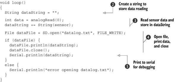
Logging your data couldn’t be any easier. First you must check to make sure your SD card is present ![]() . If it is, everything should open up properly; if not, you must return.
. If it is, everything should open up properly; if not, you must return.
Once it’s all set up, you can start your main loop, create a String to store your data ![]() , and then read and store the current sensor reading into a String
, and then read and store the current sensor reading into a String ![]() . Next, you open the data file and print the data to the file before calling close
. Next, you open the data file and print the data to the file before calling close ![]() . You can also print the data to the console for debugging
. You can also print the data to the console for debugging ![]() .
.
You can connect any sensor you want to the analog input, whether it’s a potentiometer, a temperature sensor, or an ultrasonic rangefinder. Once you have all your data, plug the SD card into your computer and open the file in your favorite text editor or programming environment. From there you can start graphing and visualizing your data and hopefully get a better understanding of its trends.
If you want to share your data logging with the outside, passing around your SD card isn’t the best option. For that, you might want to use Cosm, an online resource for sharing live data feeds with others around the world.
8.8. Cosm
Cosm, formerly Pachube (pronounced “patch-bay”), is an exciting open source community for sharing live data feeds online. You can create both public and private feeds that servers and clients connect to in order to send and receive data from anywhere in the world. Data is sent in a human-readable format (XML), and Cosm provides interesting data visualizations of the feed that you can monitor via the web.
In this section, you’re going to use an Ethernet-powered Arduino to send the values of a sensor to a Cosm feed, and also receive sensor data from another online feed. Let’s get started.
8.8.1. Sign up for an account and get an API key
The first step is creating a Cosm account at www.cosm.com and getting an API key. The API key is what gives you access to create, delete, retrieve, edit, and update your Cosm feeds.
If you’re sharing your project with others, you should keep your master API key private and instead use the Cosm user control panel to create a new secure sharing key for others to use. With sharing keys, you have full control over who has access and what functionality they have.
Once you’ve created an account, log in and go to the Keys page by navigating the main user menu (pictured in figure 8.11). There you’ll see your Master API Key; write this down and keep it handy, as you’ll need it later.
Figure 8.11. Main Cosm user interface

8.8.2. Creating a new data feed
You’re going to create a new Cosm data feed that you’ll send your sensor readings to.
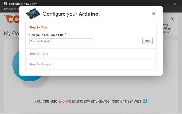
If you’re logged into your account, click the big blue + icon if this is the first Cosm feed you’re creating, or the button that says +Device/Feed if you have already created other feeds. When prompted with the question, “What type of device/feed would you like to add?” select Arduino. You’ll then be prompted with a display similar to figure 8.12. Give the feed a title and a few descriptive tags (you can, of course, change this later). Click Create, write down your Feed ID, and then click Finish— your new feed is all set.
Figure 8.12. Creating a new Cosm feed to log sensor data
Note
By selecting Arduino as the device type, the feed is automatically set up to listen—this means the Arduino will be responsible for “pushing” data to your Cosm feed. You’ll notice this option in the feeds control panel under General, or when creating a new feed and selecting the Something Else type.
Your feed is now set up and it’s ready to receive information. With your account, API key, and feed ID ready to go, you’re set to get logging in section 8.8.3. If you forgot to write down your feed ID, you can retrieve it by browsing to your feed (simply click your feed name from the Cosm console).
8.8.3. Sketch for Cosm sensor logging
Talking to Cosm is easy. In this example, you’ll log the readings from a potentiometer to a Cosm feed every ten seconds.
Note
In order to understand the workings of communicating with Cosm, you’ll connect and send everything by hand in this example. Once you’re familiar with how things work, you can save on a few lines of code—check out the wonderful Cosm Arduino library downloadable at https://cosm.com/support/libraries.
Enter the following code in the Arduino IDE.
Listing 8.8. Cosm sensor logging code


First, you’ll change the arguments for your Cosm feed settings ![]() . Make sure your API key is in quotes, because it’s supplied as a String. Next, configure your network settings by supplying the MAC address and manual IP address
. Make sure your API key is in quotes, because it’s supplied as a String. Next, configure your network settings by supplying the MAC address and manual IP address ![]() , in case DHCP fails when connecting in setup
, in case DHCP fails when connecting in setup ![]() .
.
Next you enter the main loop() where you’ll read the current sensor data ![]() . You check to see if there is any incoming data, and print it to the console for debugging
. You check to see if there is any incoming data, and print it to the console for debugging ![]() . If you were previously connected but are no longer connected, you must stop the client
. If you were previously connected but are no longer connected, you must stop the client ![]() . Finally, if you’re not connected and the interval time between sending messages has been met, you must connect and send
the current data out
. Finally, if you’re not connected and the interval time between sending messages has been met, you must connect and send
the current data out ![]() .
.
You actually call a subroutine called sendData(). This is a convenience function to establish a connection with the Cosm feed ![]() and send over your data. First, you must initiate the PUT command to talk to your feed
and send over your data. First, you must initiate the PUT command to talk to your feed ![]() , and then supply your API key
, and then supply your API key ![]() . Then the function takes care of formatting the message (data) and passes along the data to Cosm
. Then the function takes care of formatting the message (data) and passes along the data to Cosm ![]() . Finally, you store the time the message was sent
. Finally, you store the time the message was sent ![]() so you can calculate when to send the next message.
so you can calculate when to send the next message.
8.8.4. Upload and test
You can now connect your Arduino Ethernet Shield and USB cable and upload the code to your Arduino. You should be all set! Check your feed’s page on Cosm, and you should see your sensor being logged online. If you don’t see your sensor data, open up the Arduino IDE and click the Serial Monitor button to open up a serial connection for debugging.
8.9. Summary
In this chapter, you began to explore the broad spectrum of communications made possible with the Arduino. You started by getting your Arduino networked and on the internet. Using the Ethernet Shield, you turned your Arduino into a server ready to dish up information whenever a client has an appetite. Then you went a step further and patched your Arduino into Twitter, broadcasting button presses for the world to see. Because communicating with the Arduino wirelessly is useful in so many applications, we also explored communication with your Arduino both over Wi-Fi and Bluetooth technology.
The communication channels possible with your Arduino are far-reaching, and there are many ways you can communicate with other devices and peripherals. One such channel is called SPI, and in this chapter you learned how other devices and shields (such as the SD card and Ethernet Shields) use SPI to communicate with the Arduino. You even used SPI yourself to control digital potentiometers.
With all of these powerful means of communication at your disposal, we looked at data logging, an essential aspect of communication and interaction. Not only did we investigate storing information on local memory, but also storing it online using the powerful data logging service called Cosm.
How and what you choose to share is up to you; perhaps you want to have remote sensors in various environments that send their data to your feed, and are later sonified in a gallery installation. Perhaps you want to tap into other public feeds that are logging everything from seismic data to the temperature, humidity, dew point, and soil moisture of a garden in the UK, and use that to influence a virtual space. Whatever the scenario, there are virtually unlimited possibilities when it comes to the types of information your data feed can communicate, and the way you choose to interpret the information.
The applications discussed in this chapter are the tip of the iceberg. You can use the communication topics covered here in many ways, and it’s this open-endedness that makes the Arduino such a powerful communication tool. Think about your project’s goals and ask yourself whether putting your project online for the world to see or interact with would be useful. Could it tap into online resources? Does it need to communicate with other peripherals? Would it be useful to log certain data over time? With Arduino, the tools are in your hands.
But let’s not stop there. Next, in chapter 9, we’re going to look at how to interface the Arduino with game peripherals such as the Nintendo Wii Nunchuk and Xbox controller.