
Chapter 9. Game on
- Connecting an Arduino to a Wii Nunchuk
- Arduino port manipulation
- Connecting an Arduino to an Xbox controller
- Using the USB Host Shield
It’s time to dig out that old game controller that’s lying unused in the cupboard, or alternatively, borrow one from your kids. Game controllers are a great way to control things on the Arduino. From robots to flying vehicles, they tend to be relatively low-cost because so many were mass-produced, and eBay and junk sales also offer a steady second-hand supply.
We’ll start by looking at one of the controllers made for the Nintendo Wii games console—the versatile Nunchuk. Then we’ll look at one of its main rivals, the Microsoft Xbox 360 and its USB controller. You’ll learn how to get the controllers set up and running so you can use them in your own projects.
9.1. Nintendo Wii salutes you
Nintendo launched the Wii console to great acclaim late in 2006, although its graphics felt inferior to some of the existing games consoles, such as Microsoft’s Xbox and Sony’s PlayStation. The Wii had a unique games interface controller that was incredibly easy to use and communicated wirelessly with the main console. This controller, coupled with its family-themed games, made it a runaway success, with sales of over 90 million units. You’ll find plenty of available games controllers.
The Wii is supplied with two main controllers, the Nunchuk, shown in figure 9.1, and the Wii remote. Let’s look at the Wii Nunchuk and see how you can use it with the Arduino.
Figure 9.1. Wii Nunchuk

9.1.1. Wii Nunchuk
The Wii Nunchuk, shown in figure 9.1, is available from a wide range of suppliers, with prices from around $15 for an official version to $10 for one of the many compatible copies.
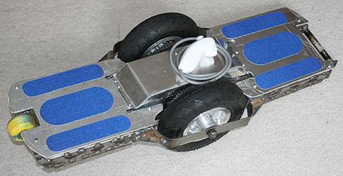
The Nunchuk packs in quite a few features: a built-in two-axis proportional analog joystick, two on-off buttons, and a three-axis accelerometer (more on this in a moment). Community projects have included controlling a motorized self-balancing skateboard (shown in figure 9.2), manipulating robot arms and servomotors, and designing small robots. The Nunchuk is also useful if you’ve built your own arcade games based on the Arduino. The video game shield kit designed by Wayne and Layne can use one or two Nunchuks and is brilliant for anyone wanting to recreate the original Atari Pong or the classic Space Invaders.
Figure 9.2. A self-balancing motorized skateboard built by John Dingley, UK
Let’s take a closer look at the individual components of the Nunchuk, starting with the three-axis accelerometer.
Three-axis Accelerometer
An accelerometer, as its name suggests, measures changes in acceleration.
The technical definition of acceleration is rate of change of velocity with respect to time. Or more plainly, it’s how quickly something speeds up. For example, a car that reaches 60 mph in 5 seconds has greater acceleration than a car that reaches 60 mph in 10 seconds.
Accelerometers are used in all sorts of devices, including tablets and smartphones, where they’re used to detect the angle at which you’re holding or turning the screen, and air bags in cars, which are deployed when a car rapidly stops due to a collision.
The accelerometer contained in the Nunchuk and many other games controllers measures acceleration as the change in angular movement of the controller, and it can detect very small changes in angle. Many games controllers use one or more three-axis accelerometers and can detect small changes in the x, y, and z directions. Figure 9.3 shows this a little more clearly.
Figure 9.3. Angular rotation of three-axis accelerometer

Accelerometers are used in Arduino-based projects in a multitude of ways: flying a remote-controlled plane or quadrocopter, playing digital musical instruments with gestural user input, and detecting if something is tilted or gets knocked.
In chapter 8 we looked at manually communicating the values from an accelerometer to the computer using Wi-Fi; now, we’ll tap into the ultra-low-cost Wii Nunchuk controller, which not only gives us an accelerometer in an easy-to-grip form, but some extra modes of input that make it a versatile input controller for your projects.
Joystick
The joystick on the Nunchuk is easily controlled with your thumb and is fully proportional, so it reports both the direction and how far you’ve moved the joystick. The Nunchuk fits nicely into your hand and the joystick is easily manipulated with your thumb.
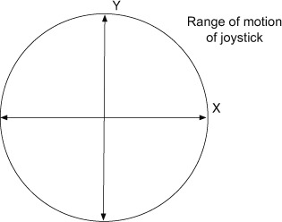
The joystick returns numbers for the x and y axes, as shown in figure 9.4. As you can see, the joystick position can be anywhere within the circle.
Figure 9.4. Range of motion of Nunchuk joystick
Buttons
In addition to the joystick, the Nunchuk has two buttons at the front of the controller: a large one labeled Z and a smaller one labeled C. The buttons are simple momentary on-off switches, which means they report whether they’re pressed or not.
Note
By keeping track of button presses on the Arduino itself, it’s easy to turn momentary buttons into toggle buttons if you so desire. If you get stuck, look at one of the many examples of doing this on the Arduino user forums, or download the toggle library called TButton, which also packs a few extra features.
You’ve seen what a Nunchuk controller can offer, but how do you get access to all this functionality so you can use it with your Arduino projects?
9.1.2. Nunchuk connections
How do you connect your Arduino to a Nunchuk? Luckily Nintendo uses a well-known communication protocol called two-wire interface (TWI or I2C), which we looked at in chapter 4. To recap, the two-wire interface is used to communicate with low-speed devices and only requires two pins, as shown in table 9.1.
Table 9.1. Pin designations for the standard Arduino and the Mega for I2C
|
Standard Arduino |
Mega |
|
|---|---|---|
| SDA data line | Analog input pin 4 | Digital pin 20 |
| SCL clock line | Analog input pin 5 | Digital pin 21 |
You’re going to use your Arduino as a master device and the Nunchuk as its slave. We’ll look in detail at the code required to communicate between the Arduino and Nunchuk shortly, but first we’re going to look at how the Arduino can physically connect to a Nunchuk.
If you cut the end of the plug off your Nunchuk you would find four colored wires designated as in table 9.2.
Table 9.2. Color designations for wires in the Wii Nunchuk
|
Wire color |
Designation |
|---|---|
| White | Ground |
| Red | 3.3 Volts |
| Green | Data line |
| Yellow | Clock line |
Note
You don’t actually have to cut off the end of your Nunchuk—an alternative solution is shown here: www.flickr.com/photos/spyderella/6019588705.
Note
The red 3.3 volt wire can be connected to 5 volts without apparent harm, although it may shorten the life of the Nunchuk.
You don’t need to cut off the end of your Nunchuk to use it, as the end connector is female with six holes, only four of which are used. Figure 9.5 shows an end view of the connector. You can use jumper wires to connect from the connector to your Arduino.
Figure 9.5. Nunchuk end connector

An alternative that I like, as it gives a very good connection and is easy to use, is an adaptor or breakout board that can connect directly to the header on the Arduino (or to a breadboard) on one end, and to the Nunchuk plug on the other. Two low-cost breakout boards, available from a number of sellers, are the WiiChuck designed by Tod E. Kurt, shown in figure 9.6, and the NunChucky by Solarbotics, shown in figure 9.7. Both breakout boards are sold as small kits, so basic soldering skills are required.
Figure 9.6. WiiChuck designed by Tod E. Kurt
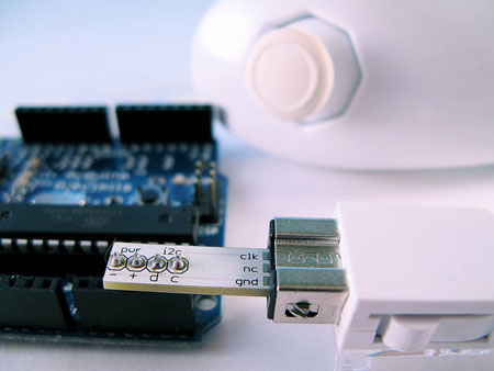
Figure 9.7. NunChucky breakout board from Solarbotics

So you have a couple of choices: you can either cut the plug off your Nunchuk cable and connect it directly to your Arduino using table 9.2 as a guide, or you can use a breakout board like the NunChucky or WiiChuck. The breakout board can be plugged directly into the header on your Arduino as shown in figure 9.6 or to a breadboard.
That covers the main ways you can connect the Nunchuk to your Arduino. Let’s move on to the code we’re going to use to talk to it.
9.1.3. Wii will talk
The easiest way to get up and running with the Wii Nunchuk controller is to use one of the available libraries, such as Gabrial Bianconi’s ArduinoNunchuk (www.gabrielbianconi.com/projects/arduinonunchuk/). Using this library, communicating with your Nunchuk can be done with ten lines of code or less. In this section, though, we’re going to take a look at what goes on under the hood, in case you wish to dig a bit deeper into Arduino territory. As such, in this section we’ll communicate with the Nunchuk from scratch and cover more advanced Arduino techniques such as port manipulation (more on this soon).
Techniques for communicating with a Nunchuk have evolved over a number of years, with contributions from Tod E. Kurt, who was responsible for some sections of the following code. We’re going to break the code down into small chunks, explaining what each piece does before viewing the complete sketch. You can skip to listing 9.1 if you’re desperate for a look now, but do come back to get an understanding of what each piece does.
Code to Communicate with the Nunchuk
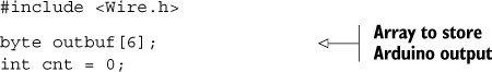
You’re going to communicate with the Nunchuk using TWI (I2C), so the first thing you must do is include the Wire library. Then you set up an outbuf array of six bytes to store the output from the Nunchuk. Finally, you set a cnt counter and set its value to 0. This will be used to keep track of the number of bytes read from the Nunchuk:
The Nunchuk device sends a packet of data that’s six bytes long, and this contains all the data from the accelerometer, the two-axis joystick, and the two buttons. The data is further summarized in table 9.3.
Table 9.3. Byte data returned from Nunchuk
|
Byte |
Description |
Typical values |
|---|---|---|
| 1 | X-axis joystick | 35 (joystick fully left) to 228 (joystick fully right) |
| 2 | Y-axis joystick | 27 (joystick fully back) to 230 (joystick fully forward) |
| 3 | X-axis acceleration | Roughly 300 (Nunchuk fully tilted left) to 740 (Nunchuk tilted right) |
| 4 | Y-axis acceleration | Roughly 320 (Nunchuk tilted backwards) to 810 (Nunchuk tilted forwards) |
| 5 | Z-axis acceleration | Roughly 300 (Nunchuk upside down) to 720 (Nunchuk upright) |
| 6 | Button states (bits 0/1) Least significant bits (LSBs) of each accelerometer (bits 2–7) |
Bit 0: Z-button (0 = pressed) Bit 1: C-button (0 = pressed) Bits 2–3: x acceleration LSBs Bits 4–5: y acceleration LSBs Bits 6–7: z acceleration LSBs |
Code to Set Up and Power the Nunchuk
You’ve set your initial variables and allocated a buffer for the received data, so you can now move on to the setup function where you’ll prepare the Arduino to work with the Nunchuk:
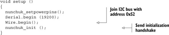
In the first part of this code, you call the nunchuk_setpowerpins() function. You then initialize the serial port with Serial.begin(19200), setting the baud rate to 19,200. You’ll use the serial port to monitor the data sent from the Nunchuk.
Next it’s time to initialize the Wire library with Wire.begin(). Finally, you call a function called nunchuk_init() to set up the Nunchuk so it will send back data when requested.
Note
You only need to call the nunchuk_setpowerpins() function if you’re using a breakout board like the NunChucky or WiiChuck that’s plugged directly into your Arduino’s headers, or if analog pins A2 and A3 are being used for ground and power respectively. The nunchuk_setpowerpins() function isn’t suitable and would need to be modified for use with an Arduino Mega, or if you’re using the Arduino onboard 5 volts and ground to supply power.
Let’s look at that first function called nunchuk_setpowerpins():
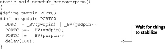
At first glance this function looks fairly complicated, but we’ll break it down to see what’s going on. The function uses port manipulation to set analog pin 3 to power (5 volts), and analog pin 2 to ground.
Arduinos based on the ATMega328 chip, such as the Uno, have three ports that provide fast low-level manipulation of the Arduino input/output pins. Each port gives access to a discrete set of pins:
- Port B gives access to digital pins 8–13
- Port C gives access to analog pins A0–A5
- Port D gives access to digital pins 0–7
Additionally, three registers control each port; the three registers are DDR, PORT and PIN:
- DDR register—This register sets individual pins as either input or output. The register state can be written to and read from.
- PORT register—This register sets the state of a pin’s output: HIGH or LOW. The register state can be written to and read from.
- PIN register—This register can only be read from and provides the state of the inputs.
Each bit of each port controls a single pin. For example, the PORTC register controls port C. Port C consists of analog pins A0–A5 (A6 and A7 are only available on the Mini).
The bits in the DDRC register (the DDR register for port C) control whether a pin is an input or an output in PORTC. For example, the following command sets pins 1 and 3 as inputs and the rest as outputs:
DDRC = B11111010;
PORTC is the register for the state of the outputs. The following command sets pins 1 and 3–7 HIGH; these pins will only be set at 5 volts if they have previously been set as outputs by the DDR register:
PORTC = B11111010;
Reading the PINC register would allow you to read the state of all the PORTC pins simultaneously.
In the nunchuk_setpowerpins() function, the #define pwrpin PORTC3 and #define gndpin PORTC2 lines assign bit offsets, so PORTC2 is bit 2 of the PORTC register.
In the next line, you have this:
DDRC |= _BV(pwrpin) | _BV(gndpin);
DDRC is the direction register for port C, so this line sets the pwrpin and gndpin bits as outputs using the _BV macro.
A macro is a method of performing a series of instructions with a single command, and the BV (bit value) macro is used to perform bitwise manipulation using bitmasks. Bitwise manipulation is the manipulation of the individual bits of a byte; a byte is made up of 8 bits numbered 0–7 with 0 being the least significant bit (LSB).
Operators can be used with the macro to operate on individual bits. These are some of the operators:
|
Operator |
Description |
|---|---|
| |= | Sets bit |
| | | Logical or |
| &= ~ | Clears bit |
Here are a couple of examples. The following line sets bit 0 only:
PORTC |= _BV(0);
The next line clears bit 1 only:
PORTC &=~ _BV(1);
Using bit operators you can manipulate multiple bits at a time. The following line sets bits 0, 2, and 4:
PORTC |= _BV(0) | _BV(2) | _BV(4);
The next line clears bits 1 and 3:
PORTC &=~ _BV(1) | _BV(3);
Having set pwrpin and gndpin as outputs, the next line clears and sets the gndpin to LOW:
PORTC &=~ _BV(gndpin);
The following line sets the pwrpin to HIGH, 5 volts:
PORTC |= _BV(pwrpin);
The last line, delay(100);, is a 100-millisecond delay to allow the supply to stabilize.
Let’s now have a look at the last function in the setup routine, nunchuk_init(), which sends a series of bytes commanding that the Nunchuk return its data, when asked, in an unencrypted format:

In this function, you set up the Nunchuk so that it’s ready to send data. Each device on an I2C network has an ID or address. The Nunchuk has a device address of 0x52, so to send information to it, you start each transmission with Wire.beginTransmission (0x52). You then prepare to send one or more commands or data packets to the address on the device. The data packets to be sent are queued in a buffer and are sent when the command Wire.endTransmission() is issued.
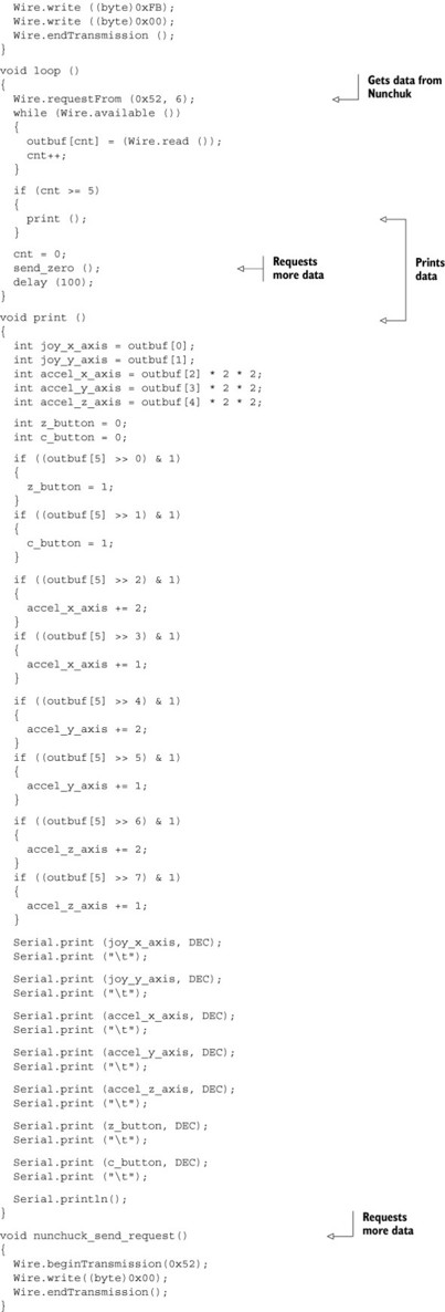
Having looked at the functions in the startup part of the sketch, we can now move on to the main loop function.
Code for the Main Loop
You’ve set the initial variables and set up the Nunchuk and provided it with power. The main loop comes next, where you obtain the data from the Nunchuk and then process it:

In the loop, your first call is to request the data from the Nunchuk with Wire.request-From(0x52, 6). This command has two parts: the address of the device, 0x52, and the number of bytes requested, 6. You next read in the 6 bytes with a while loop:
while (Wire.available ())
{
outbuf[cnt] = (Wire.read ());
cnt++;
}
The bytes read using Wire.read are stored in the outbuf array, with cnt being used to increment the index of the array. You check that you’ve received your 6 bytes and then print them with a print() function (more on that soon). In the loop, you call the send_zero() function, which requests the next set of bytes. Finally, you call a small 100-millisecond delay, delay(100), before starting the loop again.
Code to Print the Output
Let’s investigate the main parts of the print function. Here’s how it begins:
int joy_x_axis = outbuf[0];
int joy_y_axis = outbuf[1];

int accel_x_axis = outbuf[2] * 2 * 2;
int accel_y_axis = outbuf[3] * 2 * 2;
int accel_z_axis = outbuf[4] * 2 * 2;

int z_button = 0;
int c_button = 0;
Variables are initialized for the joystick’s x and y axes and they’re assigned values from the outbuf byte array. The accelerometer’s x-, y-, and z-axis variables are similarly initialized and assigned values from the outbuf array. You multiply the last three variables by 2 * 2, because the acceleration data is 10 bits and you’ve only provided the most significant bits so far.
The remaining two bits for each acceleration value are obtained from the remaining byte, which also has the button state information for buttons C and Z:
if ((outbuf[5] >> 0) & 1)
  {
    z_button = 1;
  }
  if ((outbuf[5] >> 1) & 1)
  {
    c_button = 1;
  }
  if ((outbuf[5] >> 2) & 1)
  {
    accel_x_axis += 2;
  }
  if ((outbuf[5] >> 3) & 1)
  {
    accel_x_axis += 1;
  }
  if ((outbuf[5] >> 4) & 1)
  {
    accel_y_axis += 2;
  }
  if ((outbuf[5] >> 5) & 1)
  {
    accel_y_axis += 1;
  }
  if ((outbuf[5] >> 6) & 1)
  {
    accel_z_axis += 2;
  }
  if ((outbuf[5] >> 7) & 1)
  {
    accel_z_axis += 1;
  }
Each bit of the byte needs to be checked and its value added to the appropriate variable.
Finally the value of each variable is output to the serial port:
Serial.print (joy_x_axis, DEC);
Serial.print ("	");
The Serial.print(" ") call adds a tab between each variable printed.
The last function we’re going to look at is send_zero().
Code for send-request function
The nunchuck_send_request() function is the final part of the puzzle. Having initialized the Nunchuk, powered it up, and printed the data received from it, you can now request more data with this function:
void nunchuck_send_request ()
{
  Wire.beginTransmission(0x52);
  Wire.write((byte)0x00);
  Wire.endTransmission();
}
This function transmits a value of 0 to the Nunchuk at address location 0x52; this is a “request to read” command that’s sent to the Nunchuk.
The Complete Sketch
That covers all the code we need for our sketch, so without further ado, here’s the complete code listing.
Listing 9.1. Sketch to communicate with Nunchuk using I2C

You’ve now seen a couple of ways to connect a Nunchuk to the Arduino, and you’ve got the sketch to enter into the Arduino IDE. It’s time to move on to testing.
9.1.4. Wii will test
Connect the Nunchuk to the Arduino using your preferred method, and then upload the sketch from listing 9.1. Open the serial monitor to observe the effects of moving the Nunchuk.
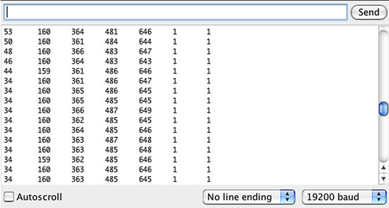
Try moving the Nunchuk about in various directions—tilt to the left and then to the right and observe how the x-axis acceleration alters. Move the Nunchuk forward and backward to observe the y-axis acceleration varying. Turn it upside down to see how the z-axis acceleration varies. Try moving the joystick and pressing the buttons. Some typical output to the serial monitor is shown in figure 9.8.
Figure 9.8. Typical output from Nunchuk to serial monitor
You’ve learned how to connect a Nunchuk to an Arduino and you’ve looked at the code involved in a typical sketch. You should now feel confident about using a Nunchuk in your own projects. Whether you want to use the joystick or accelerometers to control the position and tilt of a webcam using a servomotor, or you want to send the data into Processing to control a retro video game you’ve been working on, there are many unique applications for the affordable Nunchuk.
But although the Nunchuk is a fantastic game controller, it’s by no means your only option when thinking about readily available controllers for your projects. Controllers come in many different shapes and sizes, and in the next section we’re going to look at a controller from one of the Nintendo Wii’s main competitors: Microsoft’s Xbox 360.
9.2. Release the Xbox
Microsoft released the Xbox 360 game console in 2005 and at the time of this writing has sold over 57.6 million units. Figure 9.9 shows a typical controller.
Figure 9.9. Xbox 360 game controller
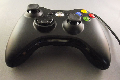
The Xbox controller has the following buttons:
- 2 analog sticks
- 2 analog triggers
- 11 digital buttons
- 1 digital D-pad
The wide range of buttons and joysticks on the controller make it ideal for controlling complex projects requiring multiple inputs, such as powered robots, complex light or sound displays, MIDI music instruments, or animatronics.
There are two versions of the Xbox controller, a wired and a wireless version. Both have the same functionality. We’re going to concentrate on the wired controller in this chapter because it has a USB plug on it that, with the addition of a USB shield, can plug directly into an Arduino.
Note
The Xbox wireless controller also comes with a USB plug, but it can only be used to charge the controller’s onboard batteries. It’s possible to purchase an adaptor that has a USB connection and can also connect to a wireless controller. You can use techniques similar to the ones we’ll discuss to connect to that version of the controller instead.
Having chosen the wired controller, let’s take a look at what you need to connect it to your Arduino.
9.2.1. Getting connected
The Xbox controller communicates using a USB connection. A standard Arduino doesn’t have an onboard USB connection suitable for plugging the games controller into, so you’ll need to add a USB Host Shield.
In this example we’re using version 2.0 of the USB Host Shield designed by Oleg Mazurov, available from Circuits@Home (www.circuitsathome.com/products-page/arduino-shields). The shield is shown in figure 9.10.
Figure 9.10. Version 2.0 of the USB Host Shield from circuitsathome.com

The USB Host Shield will allow you to connect to a range of USB devices, including mice, keyboards, and game controllers. In addition to the Host Shield, you’ll need to download and install a software library.
9.2.2. USB Host library
To use the USB Host Shield, you’ll need to download and install the USB Host Shield library from https://github.com/felis/USB_Host_Shield_2.0. Find the Downloads link on the right, and click the “Download as zip” or “Download as tar.gz” button. Extract the contents to your Arduino/libraries folder.
Once the library is installed into the Arduino IDE, it will include some sample sketches. You’ll use one of the sketches to discover information about the Xbox controller so that you can interface with it. The same techniques can be used with other USB devices to learn how to connect to them.
The USB Protocol
A thorough description of the USB protocol is beyond the scope of this book, as the protocol is complex and contains many parts. Full information and downloadable documents describing the protocol are available from the USB site (http://usb.org).
For an excellent overview and description of the main elements of the protocol, we highly recommend visiting the “USB in a Nutshell” explanation on the Beyond Logic website: http://www.beyondlogic.org/usbnutshell/. One of the main takeaways is that a USB device, when requested by a host device, should describe how it works and what is required to translate the information it provides. Unfortunately, as you’ll see, this is not always the case in practice.
9.2.3. Learning about the Xbox controller using the USB Host Shield
The sample sketch you’re going to use to connect to your controller in this section is called USB_desc, which can be found in the File menu, as shown in figure 9.11.
Figure 9.11. Select the USB_desc example sketch
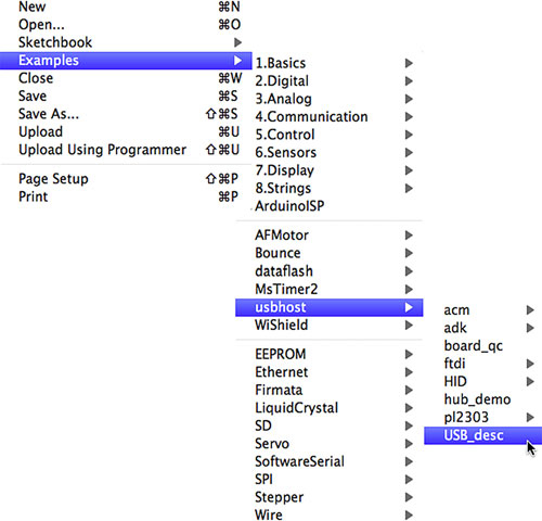
Connect the USB Host Shield to your Arduino, plug in the Xbox controller, load and run the example sketch, and open the serial monitor (setting the baud rate to 115,000 baud). The sketch issues a series of commands to the connected USB device—in this case your Xbox controller—and outputs the results to the serial monitor. The sketch outputs a lot of data, but we’ll look at the output a piece at a time to see what it tells you.
Note
All values returned are hexadecimal values.
Take a look at the first piece of data as shown in figure 9.12.
Figure 9.12. Device descriptor and configuration descriptor
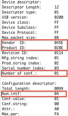
The first piece of data shown in figure 9.12 provides the “device descriptor” and “configuration descriptor.” A USB device can only have one device descriptor—it provides important information about the device, including the vendor ID, product ID, and the number of configurations available on the device. The majority of devices only have one configuration. In figure 9.12 you can see that the vendor ID is 045E (which corresponds to Microsoft), the product ID is 028E, and the number of configurations is 1.
The configuration descriptor provides information about the configuration of the device, such as the number of interfaces the device has and its maximum power consumption. All USB devices must have at least one interface, designated interface 0. An interface groups together information about endpoints; endpoints are addresses where data is transferred, and they can be either data providers or data consumers. Looking at the configuration descriptor in figure 9.12 for the Xbox controller, you can see “Num.intf: 04”, meaning that the controller has 4 interfaces.
The interface descriptors make up the rest of the data output to the serial monitor by the USB_desc sketch. Each interface contains some common information, including the number of endpoints in that interface and the interface class, subclass, and protocol. It then goes on to describe each endpoint, including the endpoint address, its attributes, the maximum packet size for data, and the polling interval. We’re going to concentrate on interface descriptor 00, as this is the main control and report interface for the Xbox controller.
Take a look at interface descriptor 00, as shown in figure 9.13.
Figure 9.13. Description of interface 00 for the Xbox controller

You can see that figure 9.13 shows the description for interface number 00, and the interface has 2 endpoints at addresses 81 and 01 (note that these are hex values, not decimal). Bit 7 of the address determines the direction of data for the endpoint, with 1 being “in” and 0 being “out.” You can see that you have one endpoint in and one out, where hex 81 equals 10000001 binary. The maximum packet size is 0x20 bytes; packet sizes tend to be given in multiples of 8.
The endpoint attribute (attr.) indicates the type of endpoint. Endpoints with an attribute of 03 are classified as interrupt endpoints. The polling interval is the period of time between interrupt transfers in milliseconds.
Note
An endpoint interrupt isn’t the same as the type of interrupt we learned about back in chapter 2, where an immediate response occurred in program execution. An endpoint interrupt is an indicator that informs the host device that it has data waiting when it’s polled by the host.
Also in figure 9.13, the values for intf. class, intf. subclass, and intf. protocol are given by usb.org and can be used to specify supported classes. This allows many devices to be supported by a few class drivers instead of requiring individual drivers for each device. For example, a value of 03 for intf. class, according to the USB protocol, would represent a class interface for a human interface device (HID), like a mouse, keyboard, or joystick. For the Xbox controller, the value of FF means the class is vendor-specific, which potentially makes your job a little more complicated.
You’ve now learned about the Xbox controller’s device and configuration descriptors, interface 00 and its associated data endpoints, how often the endpoints should be polled, and the maximum sizes for the packets of data. Next we’ll look at the format of the data packets or reports.
9.2.4. Xbox reporting for duty
In a conventional USB device, we could delve to a deeper level and look at the data-packet report formats for each endpoint. But as we’ve seen, the Xbox controller masks that information and describes its interface classes as vendor specific. We need to look to other sources to get information about the report formats.
An excellent online source in this case is the Free60 GamePad page, at http://free60.org/GamePad. The input report format for interface 00 is summarized in table 9.4.
Table 9.4. Xbox input report for interface 00
|
Offset |
Length (bits) |
Description |
|---|---|---|
| 0x00.0 | 8 | Message type |
| 0x01.0 | 8 | Packet size |
| 0x02.0 | 1 | D-pad up |
| 0x02.1 | 1 | D-pad down |
| 0x02.2 | 1 | D-pad left |
| 0x02.3 | 1 | D-pad right |
| 0x02.4 | 1 | Start button |
| 0x02.5 | 1 | Back button |
| 0x02.6 | 1 | Left stick press |
| 0x02.7 | 1 | Right stick press |
| 0x03.0 | 1 | Left buffer (LB) button |
| 0x03.1 | 1 | Right buffer (RB) button |
| 0x03.2 | 1 | Xbox logo button |
| 0x03.3 | 1 | Unused |
| 0x03.4 | 1 | Button A |
| 0x03.5 | 1 | Button B |
| 0x03.6 | 1 | Button X |
| 0x03.7 | 1 | Button Y |
| 0x04.0 | 8 | Left trigger |
| 0x05.0 | 8 | Right trigger |
| 0x06.0 | 16 | Left stick, x axis |
| 0x08.0 | 16 | Left stick, y axis |
| 0x0a.0 | 16 | Right stick, x axis |
| 0x0c.0 | 16 | Right stick, y axis |
| 0x0e.0 | 48 | Unused |
Message types with a value of 0x00 are normal input report messages. Those with a value of 0x01 are LED status messages. Eight-bit values are unsigned, and 16-bit values are signed little-endian. There are also other reports—messages that control the Xbox controller’s LEDs and rumble motors—but we’re going to concentrate on input reports with a message type of 0x00.
You’ve now gathered quite a lot of information about the Xbox controller, but what’s the best way to use this information? You could write a driver from scratch, or you could build upon an existing sketch or library. A good place to start is by looking at the examples provided with the USB Host Shield; these are all very comprehensive and cover a variety of USB devices.
Big-endian and little-endian describe the order in which a sequence of bytes representing a value is stored. Big-endian is where the “big end” (most significant value) is stored first. Little-endian is where the “little end” (least significant value) is stored first. In a big-endian computer, the two bytes required for the hexadecimal number FC62 would be stored as FC62. In a little-endian system, it would be stored as 62FC.
The big-endian and little-endian names derive from Jonathan Swift’s Gulliver’s Travels, in which the Big-endians were a political faction that broke their eggs at the large end and rebelled against the Lilliputian emperor who required his subjects, the Little-endians, to break their eggs at the small end.
You know that the Xbox controller is really a HID device. You also know that it doesn’t provide a comprehensive description of its report format, but from research you do know what the format is. The closest examples provided with the USB Host Shield library are the boot keyboard and mouse examples. These use a known report format to parse the report messages sent by these USB devices.
9.2.5. Let’s boot it
Mice and keyboards have a default or boot configuration that can be read. For example, all mice have a boot protocol of six bytes that provides information about which button has been pressed and the x and y coordinates of the mouse position. Similarly, keyboards have a default boot protocol, with the data returned providing information about which key has been pressed.
A default boot configuration enables the device to be easily read by a variety of host devices. Devices using a given configuration will all return at least this type of information, even though they may have more advanced capabilities, such as the sound controls on some keyboards or the scroll wheel on some mice.
You know the format of the reports and details for the interface produced by the Xbox controller, so you can do the same thing for the Xbox controller as for mice and keyboards—you can treat an Xbox controller as a boot device.
Let’s now look at the steps involved in interfacing the Arduino with the Xbox controller.
9.2.6. Interfacing with code
The HID boot examples use a number of libraries. The library we’re interested in is the hidboot library; this is made up of two files, hidboot.h and hidboot.cpp.
Note
On Windows, the files are normally found in the My Documents/Arduino/libraries/usbhost folder; on Mac OS X they’re in the Documents/Arduino/libraries/usbhost folder.
To dig deeper, carefully study these files, as the code you’re going to use is closely based on them, with a few tweaks here and there. To keep the code listings shorter in the book, the code provided doesn’t include error-checking, but it has been heavily commented to walk you through the important parts. To see good examples that include error checking, please examine the code library installed with the USB Host Shield.
The files you’ll be using in this example are included in the source code for this book: the Xboxhidboot library (listing 9.2) and the Arduino sketch (listing 9.3). The Xboxhidboot library will handle lower-level communication, and we’ll use it in conjunction with an Arduino sketch we’ll look at shortly. Rather than write the Xboxhidboot library from scratch, we’ll highlight the main functionality of the individual files in this section.
Let’s start with Xboxhidboot.h, which will be the main communicator between the USB and the Xbox controller.
Code for Xboxhidboot.h
Xboxhidboot.h performs a number of tasks including setting the structure of the report, listing the functions for the individual Xbox controller controls, and initializing the Xbox controller when it’s plugged into the USB Host Shield. It establishes communication with the controller and polls for reports, which are then parsed to establish which controls have been pressed.
Code for Xboxhidboot.cpp
Xboxhidboot.cpp, shown in the following listing, is the complementary file to Xboxhidboot.h and is the code that actually parses the returned report. In this section, we’ll quickly look at how the data is parsed.
Listing 9.2. Xboxhidboot.cpp

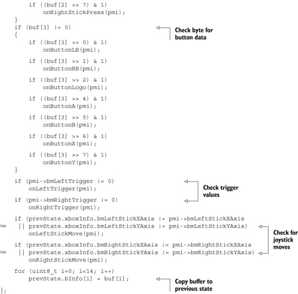
The code checks bytes two and three for button data. If data is present, it checks the byte bit by bit. Next it checks the values of the Xbox controller triggers, and then it checks the controller joysticks. Finally, the buf buffer is copied to the prevState buffer.
Now let’s look at the sketch that brings this all together.
9.2.7. Xboxhid.ino
This is the sketch that brings everything together.
Listing 9.3. Xboxhid.ino complete listing
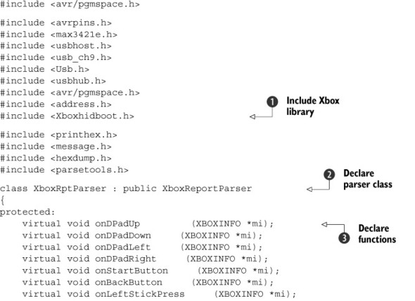

You first include the Xbox library you created in your sketch to get access to all the functions in that library ![]() . The report parser class is created
. The report parser class is created ![]() , and the functions for the individual buttons and controls are declared
, and the functions for the individual buttons and controls are declared ![]() . The functions are created
. The functions are created ![]() , and in each function you print the status for the relevant button to the serial console monitor.
, and in each function you print the status for the relevant button to the serial console monitor.
In the sketch’s setup routine, the USB device, Xbox controller, is initialized and the report parser is set ![]() . In the sketch’s loop routine, the USB device is called periodically by Usb.Task to check its state and return any report data.
. In the sketch’s loop routine, the USB device is called periodically by Usb.Task to check its state and return any report data.
That completes the software side of controlling an Xbox controller; let’s now move on to testing it with the Arduino hardware.
9.2.8. Hardware connections and testing
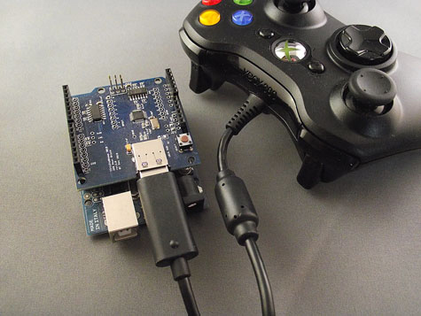
Plug the USB Host Shield onto the Arduino and then plug in your Xbox controller, as shown in figure 9.14.
Figure 9.14. Xbox controller connected to USB Host Shield and Arduino
With everything plugged in, upload the Xboxhid.ino sketch to the Arduino and open the serial monitor. Try pressing different buttons and moving the joysticks and D-pad, and observe the output in the serial monitor. Note that the monitor baud rate should be set to 115,200. Figure 9.15 shows some typical output.
Figure 9.15. Typical output from the Xbox controller

You’ve now learned how to connect an Arduino to an Xbox controller using a USB Host Shield, and in the process you gained a basic grounding in working with USB peripherals. The software listings could be much improved by adding error-checking code, and maybe that could be your next step.
9.3. Summary
In this chapter, you’ve seen how to connect an Arduino to two types of game devices: a Wii Nunchuk and an Xbox controller.
The connection to the Wii Nunchuk was relatively straightforward, and in the process you saw a practical application of the Wire library.
The connection to the Xbox controller was much more complex, both from a hardware and a software point of view. You needed to use a USB Host Shield because the controller is a USB device. The host shield can be used to connect to a variety of other devices including mice, keyboards, USB-controlled cameras, and other peripherals.
This is just the beginning! The real benefit of these controllers is that they’re affordable devices offering a number of easily manipulated controls at your fingertips. There’s nothing stopping you from connecting a graphical LCD as discussed in chapter 7, and using the joysticks on the Xbox controller to make your own Etch-A-Sketch-type of device. In fact, using an accelerometer, you can even shake the devices to clear the screen, just like the real thing. Hopefully you see the potential.
Next, in chapter 10, we’re going to look at how to connect the Arduino to iOS devices like the iPad, iPhone, and iPod Touch.