
Chapter 10. Integrating the Arduino with iOS
- Connecting your iOS device to the Arduino
- Using the Redpark serial cable
- Switching an Arduino LED from your iOS device
- Using a Slider control to vary the brightness of an LED connected to an Arduino
- Displaying output from an infrared distance sensor on your iOS device
The focus of this chapter isn’t iOS programming but instead the fundamentals of how to connect the Arduino to your iOS device. In this chapter, which is for those programming on a Mac only, we’re going to look at using the Arduino with an iPhone or iPad.
We recommend several other Manning books for learning iOS programming. If you’re new to coding, we suggest reading iOS in Practice by Bear Cahill. For more experienced programmers, we suggest either iPhone and iPad in Action by Brandon Trebitowski, Christopher Allen, and Shannon Appelcline, or Hello iOS Development by Lou Franco and Eitan Mendelowitz.
Apple has sold over 400 million iOS devices since they first launched the iPhone in 2007. You may have an iPhone or iPod touch in your pocket right now, and you might be wondering if you can use it with an Arduino. Well, you’re in luck! Previously if you wanted to connect an iOS device directly to an Arduino, the iOS device would need to be what is called “jail broken.” This invalidates the warranty and can cause other problems. Fortunately, in 2011 Redpark Product Development released a serial cable approved for use by Apple. The Redpark serial cable can be used to connect directly to a range of iOS devices including the iPhone 3GS, iPhone 4, iPad 1, iPad 2, and iPod touch version 4 and above. For devices that use the Apple Lightning connector, adapters are available to connect them to the Redpark serial cable. At time of writing, Redpark was developing a serial cable that would directly connect to Lightning connector devices.
The Redpark serial cable has opened up many opportunities to use an Arduino with an iOS device. As of yet, few examples are available, but we expect to see many exciting projects appear as more people get the cable.
This chapter will discuss the basic tools you’ll need and show you how to connect the Arduino to an iOS device. First, we’ll see how to connect the cable to an Arduino and how to send commands from your iOS device to control devices connected to the Arduino. Then we’ll demonstrate how data from a sensor connected to an Arduino can be sent to an iOS device and displayed on its screen.
To complete and run the example code in this chapter you’ll need to become a member of the iOS Developer Program for an annual fee of $99. Details can be obtained from http://developer.apple.com/programs/ios/.
To complete this chapter, you’ll need the following:
- A Mac computer capable of running Xcode 4.0 or above
- An iOS device
- An Arduino
- A Redpark serial cable
- A Lightning adapter, if required
- The Redpark SDK
- A RS232 to TTL adapter
- Xcode 4.0 or above
- A breadboard
- A selection of jumper wires
- A colored LED
- A 200 ohm resistor
- A Sharp GP2D12 IR distance sensor
Let’s get started by taking a detailed look at the most important part: the connection between an Arduino and your iOS device.
10.1. Connecting your device to the Arduino
In this section, we’ll look mainly at the hardware and software needed to connect an Arduino to an iOS device. We’ll start with the Redpark serial cable, which at one end plugs directly into an iOS device and at the other plugs into the RS232 to TTL adapter, which in turn connects to the Arduino. Once we’ve looked at what’s required to physically connect an Arduino to an iOS device, we can have a more detailed look at the software side.
10.1.1. The Redpark serial cable
The Redpark serial cable, shown in figure 10.1, is available either directly from Redpark Product Development (http://redpark.com/) or from one of the suppliers listed on their website. After purchasing the Redpark serial cable you’ll need to download the Redpark SDK from http://redpark.com/c2db9_Downloads.html.
Figure 10.1. The Redpark Product Development serial cable for use with older iOS devices

The Redpark SDK download includes a readme file that tells you how to install the SDK. There’s also a brief instruction manual giving details about the software library and its use. You can try out the example program that’s included to test the cable’s functionality with your device. The 1-meter-long cable can be used with devices running iOS 4.3.x or later and communicates serially at a maximum rate of 57.6 Kbps.
One end of the cable plugs into your iOS device, and the other is terminated with a DB-9 male connector, all pins connected. The pinout is shown in figure 10.2.
Figure 10.2. Pinout of male RS232 DB-9 connector

Table 10.1 gives a listing of all the pins for the DB-9 male connector. For this chapter, we only need to worry about the RX and TX pins.
Table 10.1. Pinouts of RS232 DB-9 male connector
|
Name |
Description |
|
|---|---|---|
| 1 | DCD | Data carrier detect |
| 2 | RX | Receive data |
| 3 | TX | Transmit data |
| 4 | DTR | Data terminal ready |
| 5 | GND | Ground |
| 6 | DSR | Data set ready |
| 7 | RTS | Request to send |
| 8 | CTS | Clear to send |
| 9 | RI | Ring indicator |
The RS232 standard uses voltages of +12 volts and –12 volts, whereas the Arduino requires TTL-level voltages, 0 and 5, so you’ll need to use a TTL to RS232 adapter. One example is the P4B, available from www.wulfden.org/TheShoppe/pa/index.shtml#P4 and pictured in figure 10.3. The P4B TTL to RS232 adapter is supplied as a kit requiring soldering, but it’s very simple to assemble.
Figure 10.3. P4B TTL to RS232 adapter

The female DB-9 connector plugs into the DB-9 male connector of the Redpark serial cable.
To complete the hardware setup, the TTL to RS232 adapter needs to be connected to the Arduino.
10.1.2. The final connection
You need to make the final connection between the TTL to RS232 adapter and the Arduino. This just requires four connections: 5 volts, ground, RX, and TX.
Note
The RX of the adapter connects to the TX of the Arduino, and the TX of the adapter connects to the Arduino RX.
Figure 10.4 shows the Arduino connected to the TTL to RS232 adapter.
Figure 10.4. P4B TTL to RS232 adapter connected to the Arduino

We’ve covered the hardware connections. Now it’s time to have a look at the code and see how you can use the Redpark SDK to create your first iOS app.
10.2. iOS code
You’ve seen how an Arduino can be connected to your iOS device, and you’ve followed the readme to install the Redpark serial cable SDK. Now it’s time to build your first app.
To program your iOS device, you’ll need a copy of Xcode 4.0 or above. Xcode is the IDE provided by Apple to enable users to develop programs and applications for Apple products. To develop and deploy applications for iOS devices and to download the latest version of Xcode, you’ll need to be a member of the iOS developer program, as mentioned in the introduction to the chapter.
Once you’ve got Xcode downloaded and installed, you can get started by opening up Xcode.
10.2.1. Creating a single-view application in Xcode
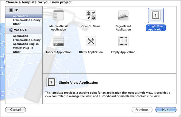
You’re now going to create a single-view application, which is the simplest type of app you can create. For this example, you’re going to create a universal project that can be deployed to either an iPhone or an iPad running iOS 5.0 or greater. The project will initially include a Switch object that can be used to turn an LED on and off.
In Xcode, select iOS Application and then Single View Application as shown in figure 10.5, and click Next.
Figure 10.5. Select Single View Application
Note
For more information on creating and building apps, check out Bear Cahill’s iOS in Practice (Manning, 2012).
Complete the project details, as shown in figure 10.6, and click Next. We’ve called the project IOSArduino.
Figure 10.6. Complete the project details.

Select Create in the next dialog box. The basic project will now be generated, and you’ll be shown the Xcode IDE.
Select MainStoryboard_iPhone.storyboard to get the initial view shown in figure 10.7.
Figure 10.7. MainStoryboard_iPhone.storyboard view

Drag a Switch object from the object library onto the viewer, in the center, and set its state to Off, as shown in figure 10.8.
Figure 10.8. Switch object dragged onto the viewer with its state set to Off

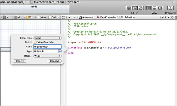
You next need to connect the Switch control to an outlet. From the menu, select View > Assistant > Show Assistant Editor. The editor should open ViewController.h. Ctrl-click on the Switch, select New Referencing Outlet from the context menu, drag to just above the @end in the editor window, and release. Name the outlet toggle-Switch, as shown in figure 10.9. Click Connect to complete adding the outlet.
Figure 10.9. Name the outlet toggleSwitch.
You next need to add a new action by repeating the Ctrl-click on the Switch, selecting Value Changed from the context menu, and dragging it to @end. Name the action toggleLED, as shown in figure 10.10, and click Connect to complete the action.
Figure 10.10. Create an action and name it toggleLED.

The next step is to import the Redpark serial cable library. Select File > Add Files to IOSArduino, and navigate to the Redpark serial SDK folder. Ours was in the home folder, but it can be in root. Select the inc and lib folders, make sure the Copy Items into Destination Group’s Folder (if Needed) option is selected (see figure 10.11), and click Add.
Figure 10.11. Import the Redpark serial SDK files.

Next, you need to import the external accessory framework. Click the project in the left pane, select the Build Phases tab, and then open the “Link Binary With” section. Click + (as shown in figure 10.12), locate the external accessory framework, and add it.
Figure 10.12. Add the external accessory framework to the project.

That’s the framework of the project set-up. Now you need to add some code to your view controller.
10.2.2. Writing the code
The code for the view controller, ViewController.h, is shown in the following listing.
Listing 10.1. ViewController.h

You import the Redpark serial cable library and set the buffer length to 1024 bytes ![]() , add a delegate to the interface
, add a delegate to the interface ![]() , set the serial cable variables
, set the serial cable variables ![]() , add the switch variable
, add the switch variable ![]() , and change weak to retain
, and change weak to retain ![]() .
.
The next step is to make some changes to the app delegate, ViewController.m, as shown in the next listing.
Listing 10.2. ViewController.m


When the app loads, the cable is set up ![]() . The toggleLED method
. The toggleLED method ![]() checks the position of the switch and sends a 1 to the Arduino if ON and a 0 if OFF. The subsequent methods are required by the Redpark serial cable delegate
checks the position of the switch and sends a 1 to the Arduino if ON and a 0 if OFF. The subsequent methods are required by the Redpark serial cable delegate ![]() . Notice the cableConnected method, where the baud rate is set and the cable is prepared for communication.
. Notice the cableConnected method, where the baud rate is set and the cable is prepared for communication.
The final step of the Xcode application, from a tip by Brian Jepson, is to declare support for the Redpark serial cable. In the project navigator, expand the Supporting Files group and click IOSArduino-Info.plist to open it. Right-click the bottom row, and from the context menu select Add Row. Select Supported External Accessory Protocols from the list. Click the triangle to the left of the key name to open up the list. In the value field for item 0, type com.redpark.hobdb9 (see figure 10.13). Select File > Save from the menu to save the file.
Figure 10.13. Declaring support for the Redpark serial cable

Now you need to deploy the app to your iOS device. Connect your device to your development machine, and select iOS Device and Run. The Xcode IDE will run and build and then deploy the project to the iOS device.
So far in this chapter, you’ve learned how to connect an Arduino to an iOS device with the Redpark serial cable and an RS232 to TTL converter, and you’ve created a single-view application, IOSArduino, with a switch. Having completed the iOS device side of the project, you now need to develop a basic Arduino sketch that will respond to the switch in your app on the iOS device and physically switch an LED on or off on the Arduino.
10.3. The Arduino gets involved
It almost feels like we’re back at chapter 1 where we switched an LED on and off, but you’ve come a long way since then. You’ve produced your first iOS program, but that’s only half of the picture. Now you need to involve the Arduino. Let’s start by looking at the Arduino sketch.
10.3.1. Sketch to switch LED from iOS device
To make things easier, this project won’t introduce any new circuitry and will use the LED built into the Arduino that’s connected to pin 13. Let’s get started.
Open the Arduino IDE and type in the following sketch.
Listing 10.3. Switching LED from iOS device

The sketch opens the serial port with a baud rate of 9,600, which matches the rate set by the iOS device ![]() , and sets digital pin 13 as an output. In the main loop, the Arduino waits for a byte to be received at the serial port.
If a byte is detected, the byte is read into the variable inByte. If the value of inByte is equivalent to 1, then the LED is switched on.
, and sets digital pin 13 as an output. In the main loop, the Arduino waits for a byte to be received at the serial port.
If a byte is detected, the byte is read into the variable inByte. If the value of inByte is equivalent to 1, then the LED is switched on.
Note
The maximum baud rate supported by the Redpark serial cable is 57,600.
We can now move on to testing the sketch.
10.3.2. Testing the sketch
Upload the sketch to the Arduino and then make the connections between the RS232 to TTL adapter shown previously in figure 10.4.
Note
You’ll need to upload the sketch when the RS232 to TTL adapter isn’t connected to pins 0 and 1 of the Arduino, as this could prevent the upload occurring.
The final piece is to connect the iOS device, the Redpark serial cable, and the RS232 to TTL adapter together. It’s probably best to power the Arduino from an external power supply, as shown in figure 10.14.
Figure 10.14. iPhone connected to Arduino, switching LED on and off
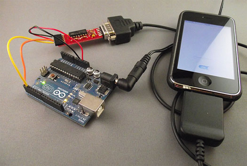
Start the IOSArduino app on your device and turn the switch on and off. If everything is connected correctly, the LED connected to pin 13 on the Arduino should turn on and off.
Now let’s develop the iOS app further by adding a slider to control the brightness of an LED connected to the Arduino.
10.4. Doing more with Xcode
It’s time to develop the IOSArduino app a little further by adding a Slider object to control the brightness of an LED connected to the Arduino. You’re going to keep the Switch control, so you need a method of distinguishing whether it’s the Switch or the Slider control that’s sending a command from the iOS device to the Arduino.
You can start by adding a Slider control to the project.
10.4.1. Adding a Slider control
Open your IOSArduino project in the Xcode IDE, open the storyboard file, and drag a Slider control onto it, as shown in figure 10.15. In the Slider, set Minimum to 0, Maximum to 255, and Current to 0. In the View section, set Tag to 9. The tag will identify which Arduino pin you want to use.
Figure 10.15. Adding a Slider control to the iPhone storyboard

You need to give a value to the tag for the existing switch as well, so select the Switch control and give Tag a value of 13, as shown in figure 10.16. The 13 indicates the pin that the Arduino LED is connected to.
Figure 10.16. Add the Tag value 13 to the Switch.

You next need to connect the Slider control to an outlet. From the menus, select View > Assistant > Show Assistant Editor. The editor should open to display View-Controller.h. Ctrl-click on the Slider, select New Referencing Outlet from the context menu, drag to just above the @end in the editor window, and release. Name the outlet moveSlider, as shown in figure 10.17. Click Connect to complete adding the outlet.
Figure 10.17. Add the moveSlider outlet.

Next you need to add a new action by repeating the Ctrl-click on the Slider and dragging it to @end. Name the action brightnessLED as shown in figure 10.18, and then click Connect to complete the action.
Figure 10.18. Add the brightnessLED action.

You now need to add some code to your view controller, ViewController.h, so that it matches the following listing.
Listing 10.4. ViewController.h

You’ve added a new outlet and a new action to ViewController.h. The next step is to make some changes to the app delegate, so that when you move the Slider control a value is sent to the Arduino. Change ViewController.m so that it matches the following listing.
Listing 10.5. ViewController.m


In this listing, a new method is added to the original toggleLED method ![]() , brightness-LED
, brightness-LED ![]() . You need to distinguish which method is sending data to the Arduino, so you use the Switch’s and the Slider’s Tag properties
to store the pin number. Each method sends two bytes to the Arduino, the first identifying the pin and the second the value.
. You need to distinguish which method is sending data to the Arduino, so you use the Switch’s and the Slider’s Tag properties
to store the pin number. Each method sends two bytes to the Arduino, the first identifying the pin and the second the value.
Build the project to check for any errors. If everything builds okay, you can deploy it to your iOS device.
It’s now time to look at the Arduino side of things, beginning with a sketch, and then building a circuit with an LED connected to pin 9.
You can probably see a pattern here: we’re building a project and making changes a little at a time. First we work on the Xcode side and then the Arduino, testing and then returning to Xcode again. We find this helps when building more complex projects. Doing incremental development simplifies the debugging as you only need to look at the last small piece of code you added.
10.5. Arduino sliding
In this section, you’re going to use the messages received from an iOS device to control switching the LED connected to pin 13 on or off and to control the brightness of an LED connected to pin 9. Listing 10.6 shows the sketch you’re going to use. Although you’re only adjusting the brightness of an LED in this example, a similar technique could easily be used to control the speed of a motor, as shown in chapter 5, or to control similar devices that respond to a PWM signal.
Listing 10.6. Sketch for iOS Slider control
#define LENGTH 2
const int ledPin = 13;
const int brightnessPin = 9;

int rxBuffer[128];
int rxIndex = 0;

void setup() {
  Serial.begin(9600);
  pinMode(ledPin, OUTPUT);
  pinMode(brightnessPin, OUTPUT);
}

void loop (){
  if (Serial.available() > 0) {

   rxBuffer[rxIndex++] = Serial.read();
   if (rxIndex == LENGTH) {

     byte pinNumber = (int)rxBuffer[0];
     byte pinValue = (int)rxBuffer[1];

     if (pinNumber == ledPin){
        if (pinValue == 1) {
          digitalWrite(ledPin, HIGH);
        }
        else {
          digitalWrite(ledPin, LOW);
        }
     }
     else if (pinNumber == brightnessPin){
       analogWrite(brightnessPin, pinValue);
     }
     rxIndex = 0;
   }
   delay(10);
  }
}
The sketch reads two bytes of data sent from the iOS device. The first byte identifies the pin number to be operated on. The second byte is the value to send to the identified pin. Either the ledPin is switched HIGH or LOW, or the brighnessPin’s value is set to alter the brightness of the attached LED.
Let’s move on and build the test circuit.
10.5.1. Arduino slider circuit
You’re now going to build a circuit using a colored LED and a 200 ohm resistor. The LED will be connected to pin 9 of the Arduino, which will respond to commands from the iOS device and be used to vary the brightness of the attached LED. Connect the circuit together as shown in figure 10.19.
Figure 10.19. LED connected to pin 9 on the Arduino

Having constructed the circuit, the next task before linking the RS232 to TTL adapter to the Arduino is to upload the sketch from listing 10.6.
10.5.2. Testing the circuit
With the sketch uploaded to the Arduino, you can go ahead and connect the RS232 to TTL adapter to the Arduino. Plug in the Redpark serial cable to your iOS device and the adapter.
Start up the IOSArduino app and notice that when you move the slider from side to side, the LED connected to pin 9 should alter its brightness. Likewise, moving the switch between on and off should turn the onboard LED connected to pin 13 on and off. The complete setup is shown in figure 10.20.
Figure 10.20. Complete setup: iPhone controlling LED’s brightness

So far, we’ve looked at sending data from an iOS device to an Arduino that responds to commands by either altering the brightness of an LED or switching an LED on or off. Next we’re going to look at communication going the other way, sending information from the Arduino, via the serial port, and displaying it on the iOS device.
10.6. Moving data to the iOS device
So far we’ve explored how to control the Arduino from an iOS device, but how about reading data from a sensor and using an iOS device to display it? In this section, we’re going to add a GP2D12 IR distance sensor, which you first encountered in chapter 6.
Let’s complete the iOS side of the project.
10.6.1. Xcode coding
Start up Xcode and load the IOSArduino project. You want to add two labels to your project: one that displays the static text “Distance” and another that displays the distance value.
Start by dragging a Label object onto the view, and set its text value to Distance. Next, drag a second Label next to the first and set its text value to 0.00. Your view should now look like figure 10.21.
Figure 10.21. Labels added to the view

You next need to connect the second label to an outlet. Select View > Assistant > Show Assistant Editor from the menus. The editor should open in ViewController.h. Ctrl-click on the label and drag to just above the @end in the editor window, and release. Name the outlet distance as shown in figure 10.22. Click Connect to complete adding the outlet.
Figure 10.22. Adding the distance outlet

You now need to add some code to your view controller, ViewController.h, so that it matches the following listing.
Listing 10.7. ViewController.h

This version of ViewController.h adds a new label variable ![]() so you can display the distance, as well as a new outlet. Note the change from weak to retain.
so you can display the distance, as well as a new outlet. Note the change from weak to retain.
The next step is to make changes to ViewController.m by adding some code to the readBytesAvailable method of the Redpark serial cable delegate. Make the changes so that they match the following listing.
Listing 10.8. ViewController.m


Notice the new code added to the readBytesAvailable method ![]() . This is a callback function that’s called when data is received by the iOS device. The method reads the bytes as a string
and outputs the result to the distance label.
. This is a callback function that’s called when data is received by the iOS device. The method reads the bytes as a string
and outputs the result to the distance label.
That completes the iOS part of the code, and it can now be uploaded to your iOS device. We’re next going to look at the Arduino side of things.
10.6.2. The GP2D12 IR distance sensor
Now you’re going to use the GP2D12 IR distance sensor that was discussed in chapter 6. The sensor only requires three connections: ground, 5 volts, and signal, which is connected to analog pin 0 on the Arduino (as was shown in circuit diagram 6.7 in chapter 6).
Add the sensor to your existing circuit. The completed circuit is shown in figure 10.23.
Figure 10.23. GP2D12 infrared sensor added to circuit

We now need to look at the Arduino sketch. You can use some of the code from chapter 6. The complete sketch is shown in the following listing. Enter the sketch into the Arduino IDE and upload it to the Arduino.
Listing 10.9. Sketch to read distance from GP2D12 sensor


The primary addition to the existing sketch is the read_gp2d12 function ![]() , which reads the input from the analog A0 pin and converts it to a distance. In chapter 6 you learned that the distance isn’t linear, so you have to perform a fancy mathematical conversion on it before returning
the distance. The distance function is called from within the main loop
, which reads the input from the analog A0 pin and converts it to a distance. In chapter 6 you learned that the distance isn’t linear, so you have to perform a fancy mathematical conversion on it before returning
the distance. The distance function is called from within the main loop![]() . The returned distance value is printed to the serial port
. The returned distance value is printed to the serial port ![]() , and it’s then received by the iOS device connected to it.
, and it’s then received by the iOS device connected to it.
Note
We found that a delay of 400 milliseconds after reading in the distance was required to display correct values on iOS. We found values as low as 250 milliseconds worked, but not consistently, so you may have to play around with this figure a little.
Once you’ve uploaded the sketch, it’s time to put everything together.
10.6.3. Testing
Connect your iOS device to the Redpark serial cable and then to the Arduino. The completed setup is shown in figure 10.24. Start the IOSArduino app and then power up the Arduino.
Figure 10.24. The completed circuit with GP2D12 sensor connected to Arduino and iPhone

Try steadily moving the sensor about and notice the values for distance changing. Figure 10.25 shows the IOSArduino app running on an iPhone.
Figure 10.25. The complete IOSArduino app running on an iPhone

10.7. Summary
In this chapter, you learned how to use the Arduino with an iOS device both to control devices connected to the Arduino and to receive information from connected sensors. We concentrated on the raw mechanics of sending data to and from an Arduino using the Redpark serial cable and an RS232 to TTL adapter. You can now use your own Objective-C programming skills to present the sent or received data in interesting and novel ways, from complex tables to brightly colored graphics.
In chapter 11 we’re going to look at ways of making wearables and how you can carry an Arduino around with you.