
Chapter 1. Hello Arduino
- The history of the Arduino
- Arduino hardware
- Hardware and software setup
- The first blinking LED
What can the Arduino be used for? The answers are surprisingly diverse. The Arduino has been used in a wide variety of projects:
- Video games such as Pong and Space Invaders that will remind some readers of their childhood and introduce others to the games their parents played when they were young, complete with monochrome graphics and simple sound effects
- Line-following robots that introduce robotics principles but are also used in factories and warehouses to deliver components along predetermined paths
- Light harps that produce music with a wave of your hands, as used internationally by the performer Little Boots
- MIDI controllers that control a series of instruments
- Self-balancing robots that mimic the Segway
These are all examples of projects built using the Arduino, a microcontroller so small that it fits in the palm of your hand. Originally designed to be used as a tool for physical computing projects by design and art students, the Arduino has been adopted as the tool of choice by communities of tinkerers and makers interested in building and prototyping their own projects.
In this chapter, we’ll start with a look at the history of Arduino and how it became the tool that many makers reach for when starting a new project. This background includes its origins at the Interaction Design Institute Ivrea and explains why it was so desperately needed. We’ll then review the different types of Arduinos available and the advantages and disadvantages of each. We’ll also look at what you need to get started: tools, equipment, and suggested electronic components. Finally, we’ll round this opening chapter out with a look at the Arduino integrated development environment (IDE) before making our first project: an LED that blinks on and off.
Let’s start by learning where the Arduino comes from.
1.1. A brief history of the Arduino
The Arduino got its start at the Interaction Design Institute in the city of Ivrea, Italy, in 2005. Professor Massimo Banzi was looking for a low-cost way to make it easier for the design students there to work with technology. He discussed his problem with David Cuartielles, a researcher visiting from Malmö University in Sweden who was looking for a similar solution, and Arduino was born.
Existing products on the market were expensive and relatively difficult to use. Banzi and Cuartielles decided to make a microcontroller that could be used by their art and design students in their projects. The main requirements were that it be inexpensive—the target price was to be no more than a student would spend going out for a pizza—and be a platform that anyone could use. David Cuartielles designed the board, and a student of Massimo’s, David Mellis, programmed the software to run the board. Massimo contacted a local engineer, Gianluca Martino, who also worked at the Design Institute helping students with their projects. Gianluca agreed to produce an initial run of 200 boards.
The new board was named Arduino after a local bar frequented by faculty members and students from the institute. The boards were sold in kit form for students to build themselves. The initial run was soon sold out, and more were produced to keep up with demand. Designers and artists from other areas heard about the Arduino and wanted to use it in their projects. Its popularity soon grew when the wider maker audience realized that the Arduino was an easy-to-use, low-cost system that could be used in their own projects, as well as a great introduction to programming microcontrollers. The original design was improved upon and new versions were introduced. Sales of official Arduinos have now reached over 300,000 units, and they’re sold all over the world through a range of distributors.
There are now a number of different versions of Arduino boards, so we’ll take a look at them in the next section.
1.2. The Arduino hardware
There have been a number of Arduino versions, all based on an 8-bit Atmel AVR reduced instruction set computer (RISC) microprocessor. The first board was based on the ATmega8 running at a clock speed of 16 MHz with 8 KB flash memory; later boards such as the Arduino NG plus and the Diecimila (Italian for 10,000) used the ATmega168 with 16 KB flash memory. The most recent Arduino versions, Duemilanove and Uno, use the ATmega328 with 32 KB flash memory and can switch automatically between USB and DC power. For projects requiring more I/O and memory, there’s the Arduino Mega1280 with 128 KB memory or the more recent Arduino Mega2560 with 256 KB memory.
The boards have 14 digital pins, each of which can be set as either an input or output, and six analog inputs. In addition, six of the digital pins can be programmed to provide a pulse width modulation (PWM) analog output. A variety of communication protocols are available, including serial, serial peripheral interface bus (SPI), and I2C/TWI. Included on each board as standard features are an in-circuit serial programming (ICSP) header and reset button.
Note
Specialist boards called shields can expand the basic functionality of the Arduino; these can be stacked on top of each other to add even more functionality.
We’re now going to look at the more commonly available Arduino models, starting with the Arduino Uno.
1.2.1. Arduino Uno
“Dinner is Served” was the blog title announcing on September 25, 2010, the arrival of the Arduino Uno (meaning one in Italian), and its bigger brother, the Mega2560. The Arduino Uno is pin-compatible with previous Arduinos, including the Duemilanove and its predecessor the Diecimila.
The major difference between the Uno and its predecessors is the inclusion of an ATmega8U2 microcontroller programmed as a USB-to-serial converter, replacing the ageing FTDI chipset used by previous versions. The ATmega8U2 can be reprogrammed to make the Arduino look like another USB device, such as a mouse, keyboard, or joystick. Another difference is that it has a more reliable onboard 3.3 volts, which helps with the stability of some shields that have caused problems in the past. See appendix C for the full technical specifications.
Figure 1.1 shows the board layout and pins of the Arduino Uno.
Figure 1.1. Board layout and pins of the Arduino Uno

The Uno is a good all-purpose Arduino and is your best bet for a starter board with its auto-switching power supply and regulated onboard 3.3 volts.
1.2.2. Arduino Duemilanove
The Duemilanove (which means 2009 in Italian) is one of the most popular Arduino boards produced, having replaced its predecessor, the Arduino Diecimila. But it, in turn, has been superseded by the newer, more up-to-date Arduino Uno. The Duemilanove features auto-switching power selection between the external and USB, and it uses the ATmega328 processor, although models prior to March 2009 used the ATmega168. Its pin layout and capabilities are identical to the Uno, and it uses the FTDI chipset for USB-to-serial communication.
If you’re purchasing a new Arduino, you should get the Arduino Uno. If you already have a Duemilanove, consider upgrading to the Uno if you need the more stable 3.3 volts or want to do some advanced programming with the ATmega8U2.
1.2.3. Arduino Ethernet
The Arduino Ethernet is a low-power version of the Arduino announced at the same time as the Uno. The main differences between it and other Arduino versions are that it has an onboard RJ45 connector for an Ethernet connection and a microSD card reader. The Arduino Ethernet doesn’t have an onboard USB-to-serial driver chip, but it does have a six-pin header that can be connected to an FTDI cable or USB serial board to provide a communication link so that the board can be programmed. It can also be powered by an optional Power over Ethernet (POE) module, which enables the Arduino Ethernet to source its power from a connected twisted-pair Category 5 Ethernet cable.
The Arduino Ethernet is ideally suited for use in remote monitoring and data logging stations with the onboard microSD card reader and a connection to a wired Ethernet network for power.
1.2.4. Arduino Mega
The big brother of the Arduino family, the Mega, uses a larger surface-mount microprocessor. The ATmega1280, the Mega, was updated at the same time as the Uno, and the microprocessor now used is the ATmega2560. The new version has 256 KB of flash memory compared to the 128 KB of the original.
The Mega provides significantly increased input-output functionality compared to the standard Arduino, so with the increased memory, it’s ideal for those larger projects that control lots of LEDs, have a large number of inputs and outputs, or need more than one hardware serial port—the Arduino Mega has four. The boards have 54 digital input-output pins, 14 of which can provide PWM analog output, and 16 analog input pins. Communication is handled with up to four hardware serial ports. SPI communication and support for I2C/TWI devices is also available. The board also includes an ICSP header and reset button. An ATmega8U2 replaces the FTDI chipset used by its predecessor and handles USB serial communication.
The Mega works with the majority of the shields available, but it’s a good idea to check that a shield will be compatible with your Mega before purchasing it. Purchase the Mega when you have a clear need for the additional input-output pins and larger memory. See appendix C for the full technical specifications.
Figure 1.2 shows the pin and board layout.
Figure 1.2. The Arduino Mega pins and layout; note the additional input-output pins and the extra serial ports compared to the Arduino Uno.

Now let’s take a look at a few more specialized Arduino options.
1.2.5. Other Arduino boards
The original Arduino has spawned a number of variations that package the design in different ways, usually in response to a need. Let’s take a look at two of them: the LilyPad and the Nano.
LilyPad Arduino
Designed by SparkFun Electronics and Leah Buechley, the LilyPad Arduino is great for textile projects and for strutting your stuff on the catwalk. It’s designed with large connecting pads that can be sewn to fabric, and there’s a range of sewable accessories available, including light sensors, buzzers, tri-color LEDs, temperature sensors, E-sewing kits, and accelerometers. This low-power version is even washable; just don’t forget to take out the batteries first.
The main difference between the LilyPad and other Arduinos is a slower processing speed of 8 MHz, as opposed to the normal 16 MHz. One thing to watch out for: the input voltage must not exceed 5.5 volts. See figure 1.3 for a picture of the LilyPad Arduino.
Figure 1.3. The LilyPad Arduino is suitable for sewing onto fabric, and there’s a range of sewable accessories available.

Arduino Nano
If your project has limited space, the Arduino Nano is the right choice. Designed and produced by Gravitech, version 3.0 of the Nano (with the ATmega328 processor) has a mini USB onboard, a compact format for use on breadboards.
The Nano has similar functionality to the Duemilanove, but it has two additional analog input pins. Power to the board is supplied either by USB or two separate pins: pin 30 can accept an unregulated supply between 6 and 20 volts, or pin 27 can accept a regulated supply of 5.5 volts. The board selects whichever voltage is the highest.
The small size of the board makes it ideal for projects with limited space.
1.2.6. Attack of the clones
From the beginning, Arduino was conceived as open-source hardware. Users were free to take the design, download the published computer-aided design (CAD) files, and produce and sell hardware based on them. This has led to the production of a number of clones or copies of Arduino, with many of the clone manufacturers taking the original specification and making their own changes.
The Arduino name is trademarked, preventing derivatives from using the Arduino name in their products unless permission is given by the Arduino team.
Seeeduino (yes, 3 e’s)
If you like the color red, this is the board to get. Designed and produced by Seeed Studio, in Shenzhen, China, the Seeeduino is based on the Diecimila design, one of the early Arduino boards, and can be purchased with either an ATmega168 or ATmega328 microprocessor. It uses low-profile surface-mount components and has a distinctive red color.
The board is compatible with the Diecimila’s pin layout and dimensions. Improvements include auto-sensing between USB and external power, and better onboard power supplies.
Seeeduino Film
The Seeeduino Film is a different take on wearables than the LilyPad’s fabric-based architecture. This flexible Arduino clone, which can also be used in data-logging projects, has a surface-mount ATmega168 on a flexible printed circuit board. Instead of shields, expansion is achieved by what the manufacturer calls frames. One frame has been produced so far, consisting of a barometer, 32 MB of flash memory, and a three-axis accelerometer, which should be more than enough to get you going.
Boarduino
The Boarduino is a small board similar to the Nano 3.0, but available as a kit only, so soldering skills will be required. Produced by Adafruit Industries, the Boarduino is designed to plug directly into a solderless breadboard. The kit is available in two versions, one with USB and the other with a serial connection for which an additional cable is required. It uses the ATmega328.
Sippino
The Sippino is a miniature Arduino-compatible clone from SpikenzieLabs sold in kit form, so like the Boarduino, it requires soldering skills. The Sippino uses the ATmega328, but it can also use the ATmega168. All the digital and analog input-output pins are brought out into a single line so it can be plugged directly into a solderless breadboard. A FTDI-USB serial cable is required to program the board.
eBay
A number of clone boards are sold on eBay, many of them copies of the Duemilanove. Here are some things to look out for in any clone: make sure it has an ATmega328 microprocessor, and that the headers are suitable for adding shields.
The first Arduino we purchased from eBay had male instead of female headers, which made it difficult to add shields. We also had to buy some special jumpers to connect to a breadboard. It was enough to get us started, but it’s better to avoid such mistakes and check that you’re buying what you really want.
1.2.7. Getting an Arduino
If you’re looking to get started with Arduinos, we recommend getting the Uno, with its superior USB connection and better regulated onboard power supply.
The Arduino Uno is available from a number of online retailers. The three most prominent in the USA are SparkFun Electronics (www.sparkfun.com), Adafruit Industries (http://adafruit.com), and Maker Shed (http://makershed.com/). In the UK, there are SK Pang Electronics (http://skpang.co.uk) and oomlout (http://oomlout.co.uk). A full list of worldwide distributors is available at the main Arduino website (http://arduino.cc/en/Main/Buy).
Once you have an Arduino, you can move on to connecting it to your system and setting up your working environment.
1.3. Setting up your working environment
Once you receive a shiny new Arduino, you’ll probably be itching to get started. This section should help scratch that itch, as we’ll look at connecting your Arduino to your computer for the first time, and you’ll learn what’s required to set up your working environment.
To get started, you’ll need an Arduino. As mentioned in the previous section, a Duemilanove or a Uno is a good place to start. You’ll also need a USB cable to connect the Arduino to your computer.
1.3.1. Software for Arduino
At the moment, your Arduino is just a board with some electronic components on it. To make it do some useful work, you need to give it instructions, which is why you need the Arduino software IDE. The Arduino software IDE provides everything required for programming the Arduino, including a number of example programs or sketches that demonstrate how to connect it to and communicate with some common devices, such as LEDs, LCDs, and some sensors.
You’ll be glad to know that, just like the hardware, the software for Arduino is open source and can be freely downloaded from http://arduino.cc/en/Main/Software. Just make sure you download the correct version for your system. Versions of the IDE are available for Windows, Mac OS X, and Linux. For full installation instructions for each platform see appendix A.
It’s important to familiarize yourself with the IDE because it’s where you’ll write all your code. In the world of Arduino, a block of code is called a sketch. A sketch gives an Arduino a list of instructions and the Arduino goes off and sketches out your idea. The IDE helps to hide much of the complexity of the Arduino, making it much easier to develop projects.
Note
The term sketch comes from Processing, a language often taught to design and art students, and on which the Arduino IDE is based. Those already familiar with programming should think of a sketch as being like a software program.
1.3.2. Basic hardware setup
The Arduino board connects to your computer via USB. The USB cable provides the 5 volts required to power the Arduino, and it provides enough power to light up a couple of LEDs and allow for some basic experimentation.
1.3.3. Your Arduino toolbox
Here’s a shopping list we recommend to someone just starting with Arduino:
- Arduino (Uno or Duemilanove)
- Mini breadboard and jumpers (used to build small circuits)
- Selection of LEDs
- Selection of resistors
- 9 volt battery
- Battery connector
- Light-dependent resistor
- Small DC motor or servo
- Piezo buzzer (a type of small loudspeaker, like those found in musical cards)
- Potentiometer (a type of variable resistor)
Typical projects you could build with these components include flashing LEDs, model traffic lights, a musical buzzer, and a light-activated switch.
If you’re feeling a little more adventurous, you could add the following components:
- Adafruit GPS and data logging shield for recording sensor data, time, and position
- Adafruit Wave shield for playing audio from an SD memory card for special effects
- Motor shield for driving a couple of motors, possibly the beginnings of robot motion
A kit of basic components, including an Arduino and a selection of components, can be purchased from a number of sellers, who often offer a discount when you purchase a kit.
Now that your working environment is set up, it’s time to write your first sketch and perform the hardware equivalent of “Hello World.”
1.4. Make something happen!
Before you rush out to pick up all those exciting attachments, all you need for your first example is an Arduino, because all of them have an onboard LED connected to digital pin 13. For this first example, you’re going to make an LED blink on and off repeatedly.
Note
In case you want to be a little more adventurous, we’ve also included instructions for adding an external LED in section 1.4.3.
1.4.1. Your first blinking LED
LEDs are available in a range of colors, but the LED connected to pin 13 on the Arduino is normally green. The LED lights up when a current is applied to it, so you can use pin 13 like a switch. When you switch it on, it will light up the LED, and when you switch it off, it will turn off the LED.
Let’s start by writing the sketch.
1.4.2. Sketch to make an LED blink
Start up the Arduino IDE and copy the following code. It might look a little overwhelming at first, but don’t worry. We’ll go into more detail about what this all means later in the chapter.
Listing 1.1. Code required to make an LED blink
void setup(){
     pinMode(13, OUTPUT);
}

void loop(){
     digitalWrite(13, HIGH);
     delay(1000);
     digitalWrite(13, LOW);
     delay(1000);
}
The code is straightforward. You’re assigning digital pin 13 as an output, and then you’re looping through some code that switches pin 13 on to HIGH or LOW for 1 second. The delay value is given in milliseconds, so 1000 milliseconds give you a delay time of 1 second.
Note
Make sure that you copy the listing exactly. Watch out for the semicolon (;) at the end of some lines and the correct use of capital letters. As far as Arduino is concerned, digitalwrite isn’t the same as digitalWrite.
1.4.3. Connecting everything
If you connect your Arduino to your computer via the USB cable, this sketch will control the onboard LED next to pin 13.
You can also control an external LED by connecting it between pin 13 and GND. The connection is shown in figure 1.4. Note that the LED must be connected the correct way around—the shorter leg is the cathode or –, and the longer is the anode or +, so push the longer lead into pin 13 and the shorter into GND. If you’re struggling with some of the electronics terms, a good primer can be found at www.kpsec.freeuk.com/compon.htm.
Figure 1.4. LED inserted between pin 13 and GND. Note that the shorter leg is connected to GND.

Note
A current-limiting resistor would normally be required to prevent the LED from burning out, and we’ll cover that in chapter 2. For now, let’s just use the existing onboard LED.
Once the LED has been inserted, you can move on to the next section to test the sketch.
1.4.4. Uploading and testing
Time to see if your sketch works! First, connect the Arduino to your computer via a USB cable. You now have a couple of settings to make between the software and the Arduino.
First you need to set the board type. Select Tools > Board and then select the type of Arduino you’re using. See figure 1.5.
Figure 1.5. In this example, the Duemilanove has been selected, but you can see there’s quite a list to choose from.

Next, you need to set the serial port because the USB sees the Arduino as a serial connection. Select Tools > Serial Port and then choose your serial port (see figure 1.6). On a system using Mac OS X for an Arduino Uno, the port will be something like /dev/tty.usbmodem; for older boards like the Duemilanove or Diecimila, it will be something like /dev/tty.usbserial. On a Windows system, the port will be identified as something like COM3.
Figure 1.6. Select the correct serial board from the list.
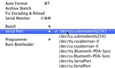
Note
Figure 1.6 shows the selection for a system using Mac OS X. The port on a Windows system will be different and will be something like COM3.
The next step is to click the Upload button in the IDE. See figure 1.7.
Figure 1.7. Click the upload button to upload the sketch to the Arduino.
![]()
Wait a few seconds, and the LED should start blinking at the rate of about once a second.
Note
The Arduino retains the program in its memory even if it’s switched off until you upload another sketch.
It’s always exciting when you see that first LED blinking and know everything is working properly, but that’s not all you can do with your Arduino. You’re now going to get a more detailed look at the IDE and take a tour of the main coding editor screen.
1.5. Touring the IDE
As stated earlier, the IDE is based on Processing, which was designed for ease of use and ease of learning. The IDE provides everything you need to write and upload sketches (programs) to the Arduino.
1.5.1. The main editor
When the IDE is first loaded, it opens with a blank sketch; the sketch is automatically given a temporary name with a date reference. The name can be changed later to something more appropriate when you save the sketch.
Figure 1.8 shows the IDE containing a sketch, with annotations for the various buttons and windows. The toolbar along the top of the main editor has the following functions:
Figure 1.8. A typical sketch with the buttons and areas of the screen labeled

- Verify— Checks sketches for errors. Errors are reported at the bottom of the screen.
- New— Opens a new sketch.
- Open— Opens up a list of previously-saved sketches and example sketches.
- Save— Saves the sketch and prompts for a name if this is the first save.
- Upload— Checks the code for errors before uploading the sketch to Arduino.
- Serial monitor— Opens the serial monitor in a new window (see figure 1.9 in the next section).
Figure 1.9. The serial monitor showing the output from an Arduino printing out an ASCII table

At the bottom of the main screen are two windows. The first provides status information and feedback; the second provides information when you’re verifying and uploading sketches. Any coding errors will also be reported here.
The code editor additionally matches the curly braces, {}, used to denote blocks of code, and it performs syntax highlighting and automatically indents your code for readability.
1.5.2. Serial monitor
The serial monitor mentioned in the previous section monitors data between the Arduino and the host computer system over the connected USB cable. The Arduino can send information using code, and it can also receive it. You can see this in figure 1.9.
The top part of the serial monitor window is used for sending data to the Arduino. You could, for example, use it to send control commands to the Arduino to turn a servomotor a varying number of degrees, or to open or close a switch. The main part of the window displays data output from the Arduino. This could be used to check the output from a GPS or to perform other signal monitoring.
The serial monitor is very useful for debugging code when linking the Arduino to a computer system running software that interacts in some way with the Arduino; you can use the serial monitor to check that the Arduino is outputting the correct data in the format expected. In the serial monitor, you can also set the baud rate used for communication, autoscroll of text, and the form of line ending that is appended to data sent to the Arduino.
1.5.3. Catching errors
Now let’s return to the main editor. The main area of the screen is the code editor where you type your code. Once you’ve finished inputting code, you have the option to either verify or upload your sketch to the Arduino.
Any code errors are reported in the bottom window. In figure 1.10 we’ve introduced an error by omitting a semicolon (;) at the end of one of the lines of code.
Figure 1.10. The code editor reports an error we’ve introduced into the code. The code checker indicates which line it thinks the error is on, as well as what it expected.

Details of the error are provided, as well as the line on which the error occurs. Hopefully the code checker can provide enough information to point you in the right direction if it doesn’t point out exactly what’s wrong. As you can see in figure 1.10, the code checker has correctly identified the missing ; and where the error occurred.
1.5.4. Process
What does the IDE actually do with your code? When you press the upload button, it checks the code for errors and performs some minor translations to convert the sketch to valid C++. The code is then compiled, which means it’s converted to a form that can be understood by the Arduino. The resulting file is then combined with the standard Arduino libraries before being uploaded to the Arduino hardware.
Now that you’ve had a tour of the IDE, it’s time to get a better sense of Arduino sketches.
1.6. Anatomy of a sketch
A typical sketch consists of two parts or routines: the first is the initialization routine called setup, and the second is a routine called loop, usually containing the main body of code. We’ll take a more detailed look at these two routines next.
1.6.1. A routine called setup
When you want to go out for a jog, there are things you must do before you can go: put on your shoes or trainers, get a bottle of water, and stretch. It’s the same with an Arduino. It must be prepared or set up before it can go to work.
This setup is contained within an initialization routine or function appropriately called setup (see the following listing). Typical things you would do in setup include initializing digital pins—setting them as INPUT or OUTPUT—and setting the baud rate for serial communication.
Listing 1.2. The setup function
void setup()
{
pinMode(13,OUTPUT);
Serial.begin(9600);
}
The setup code in listing 1.2 sets digital pin 13 as an output and configures serial communication at baud rate 9600. The void in front of setup just means the function doesn’t return a value.
Even if you don’t have anything to set up, the routine is still required or an error will be generated when verifying or uploading a sketch. Just type an empty function with a code comment:
void setup(){
      // nothing to setup
{
Now let’s look at the other required function, loop.
1.6.2. The endless loop
When you go for a jog, you keep running until you’re done (however you define done). It’s the same with an Arduino; it runs continually in a looping routine or function called loop until some condition is met or the Arduino is powered down. The following listing shows the loop for the blinking LED from listing 1.1.
Listing 1.3. An example loop function that blinks an LED on and off
void loop()
{
digitalWrite(13, HIGH);
delay(1000);
digitalWrite(13,LOW);
delay(1000);
}
In this case, the Arduino loops repeatedly, turning the LED on for a second and then off for a second, continuing until the Arduino is powered down.
Now that you know the basics of writing a sketch, it’s time to close out the chapter with an important reminder.
1.7. Commenting code
You’ve written a great piece of code that you’re really proud of. Now imagine that six months later, someone else is browsing through your past work and comes upon the same sketch, but they can’t quite figure out what it does or how it works. A simple description would help enormously. This is where commenting your code becomes invaluable.
There are two main ways to place comments in a sketch: either as a single line or as a block. A single line comment has a double slash (//) at the start of the line. This tells the compiler that it’s just a comment and can be ignored. When you want to add a block of code as a comment, start the block with /* and end with */.
Both methods are demonstrated here:
// This is a single-line comment

/* And this is a block carried over
a couple of lines
*/
Where should you put comments? Each sketch should have a comment block at the top or header of the sketch, giving a description of what the sketch does, who wrote it, the date, and the version number. The next listing shows an example header.
Listing 1.4. Example header code
/*
Code to blink LED
Author: Martin Evans
Date created : 1st September 2009
Version 1.0
*/
Single-line comments spread throughout the sketch will quickly allow you to see what the individual pieces of code do. You don’t need to comment every piece of code, just places where you think it would help you or someone else understand the code at a later date. It’s probably better to have too many comments than too few. The following listing shows some typical code comments.
Listing 1.5. Example code comments
void setup()
{
  Serial.begin(9600);

  // prints title with ending line break
  Serial.println("ASCII Table ~ Character Map");
}

// first visible ASCIIcharacter '!' is number 33:
int thisByte = 33;
/* you can also write ASCII characters in single quotes.
for example. '!' is the same as 33, so you could also use this:
int thisByte = '!'; */
We’ve looked at the code editor and the IDE, seen how a sketch is formed with the setup and loop functions, and discussed the importance of code comments.
1.8. Summary
This has been a busy chapter, and we’ve covered a lot of ground. We started by learning a little of the history of Arduino and its beginnings at the Interaction Design Institute in Italy. We saw the layout of the pins and main components of the Arduino Uno and Mega. We caught a glimpse of some other Arduino versions, including the LilyPad and the Seeeduino Film, and what they offer. You set up a working environment and wrote your first sketch, getting to see your Arduino come to life.
We looked in detail at the Arduino software IDE and the components of a sketch, with the setup and loop routines, we looked at using the serial monitor, and we saw the importance of commenting your code.
The next chapter is a tutorial that covers the gradual development of a project and the steps involved in completing it.